Beefing up/rebuilding the VE 5 speed RS5F50V
 09-22-2015, 10:48 AM
#1
2 VE's are better than one!

Thread Starter
iTrader: (31)
Join Date: Sep 2000
Location: Dallas
Posts: 7,358
Beefing up/rebuilding the VE 5 speed RS5F50V
It's well known that Nissan used the RS5F50 series transmission on a ton of cars in from the 90's through early 2000's.
The VE 5 speed had the RS5F50V transmission - V indicating locking differential.
The 4th gen and 5th gen Maxima 5 speed had the RS5F50A transmission - A indicating open differential. It's my understanding the Canadian spec 4th gen had the RS5F50V and that it was an option on USDM Infiniti I30's.
It's long been assumed that the 3rd, 4th, and 5th gens had identical transmission internals but with different bellhousings and transmission cases.
Anyway -
As some of you probably know, my blue VE is boosted and I cracked a ringland last year. So I put the car down while I rebuilt the engine. I finished my engine rebuild a couple months back - forged internals and the works. I'm going for much higher (and more reliable) power this time. So to match my new stout engine I've been looking into beefing up the transmission for about 6 months now.
Having said all that, the RS5F50A/V is used in a lot of global Nissan cars as well. The GTiR is a very popularly modded car in Australia and there is huge aftermarket support for it over there. Several companies make built gearsets for the GTiR - particularly PPG and PAR Engineering.
Because of that, it's been a well known and long time mod here - particularly for the boosted 4th gen guys - to swap in beefed up aftermarket 3rd and 4th gears designed for the GTiR. Unfortunately, the entire gearset wasn't a swap because the GTiR and Maxima have different reverse gear setups meaning if you swapped 1st and 2nd gear for a GTiR into the Maxima, the Maxima would have no reverse.
To solve that lack of reverse issue, a boosted Canadian user here back in 2008 had PAR Engineering build a complete custom ($$$$$) Maxima-specific 1-4 gearset for his 4th gen. This set came with the proper Maxima-specific input shaft that would allow the Maxima to actually have a reverse gear.
So here is where my quest comes in -
Earlier this year, I had been reading up on old bookmarked threads, scouring the interwebz, etc to confirm that the 3rd gen and 4th/5th gen share identical internals so I could see about beefing up my VE 5 speed transmission. As stated it's long been assumed the 3rd and 4th gen share identical transmissions other than the case and bellhousing.
I pulled up parts diagrams for the 3rd gen, 4th gen, and 5th gen and compared them all with their part numbers side by side by side.
It turns out the 3rd gen is identical to the 4th/5th gen EXCEPT for the reverse gear setup. Everything else between 3rd, 4th, and 5th gen 5 speeds appears to use identical part numbers. The 3rd gen has two reverse idler gears, whereas the 4th/5th gen only has one. Interestingly, the GTiR also has two reverse idler gears - which is the sole reason the entire GTiR setup will NOT work on the 4th/5th gen.
So of course this got me wondering how similar the 3rd gen and GTiR might be.
I cracked open my one of my spare VE 5 speed transmissions and took about a gazillion detailed photos of it and e-mailed the photos to Haysam at PAR who was able to confirm that the VE 5 speed and GTiR share identical internals!
Now why is this cool? This is cool because this means us 3rd gen guys can use OFF THE SHELF complete GTiR gearsets from PAR, PPG, or even Quaife, and not have to deal with prohibitively expensive custom one-off designs. Of course, many would say even off-the-shelf gearsets are prohibitively expensive. These gearsets are about twice the cost of shop rebuilds ($3k). So I guess one way to look at it is that if you blow up your stock transmission while boosted and require 2 or more rebuilds that these built gearsets will have paid for themselves. At least, that's how I'm justifying it lol.
Fast forward to now and I have bought a complete off the shelf straight-cut synchromesh 1-4 GTiR gearset from PAR in Australia (just a hair over $3k shipped right now with the exchange rate - considerably LESS expensive than it used to be). After some debate back and forth I decided to go with the straight cut and keep factory 5th gear � the helical cut gears tend to just send all the forces outwards to the case which makes you prone to breaking the transmission case itself, and keeping factory 5th gear means I won�t have annoying gear whine while cruising. It actually took 3 full months from the date I paid/ordered to arrival at my door � because even though it was an �off the shelf� item, I still had to wait in their production queue.
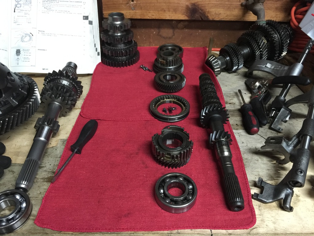
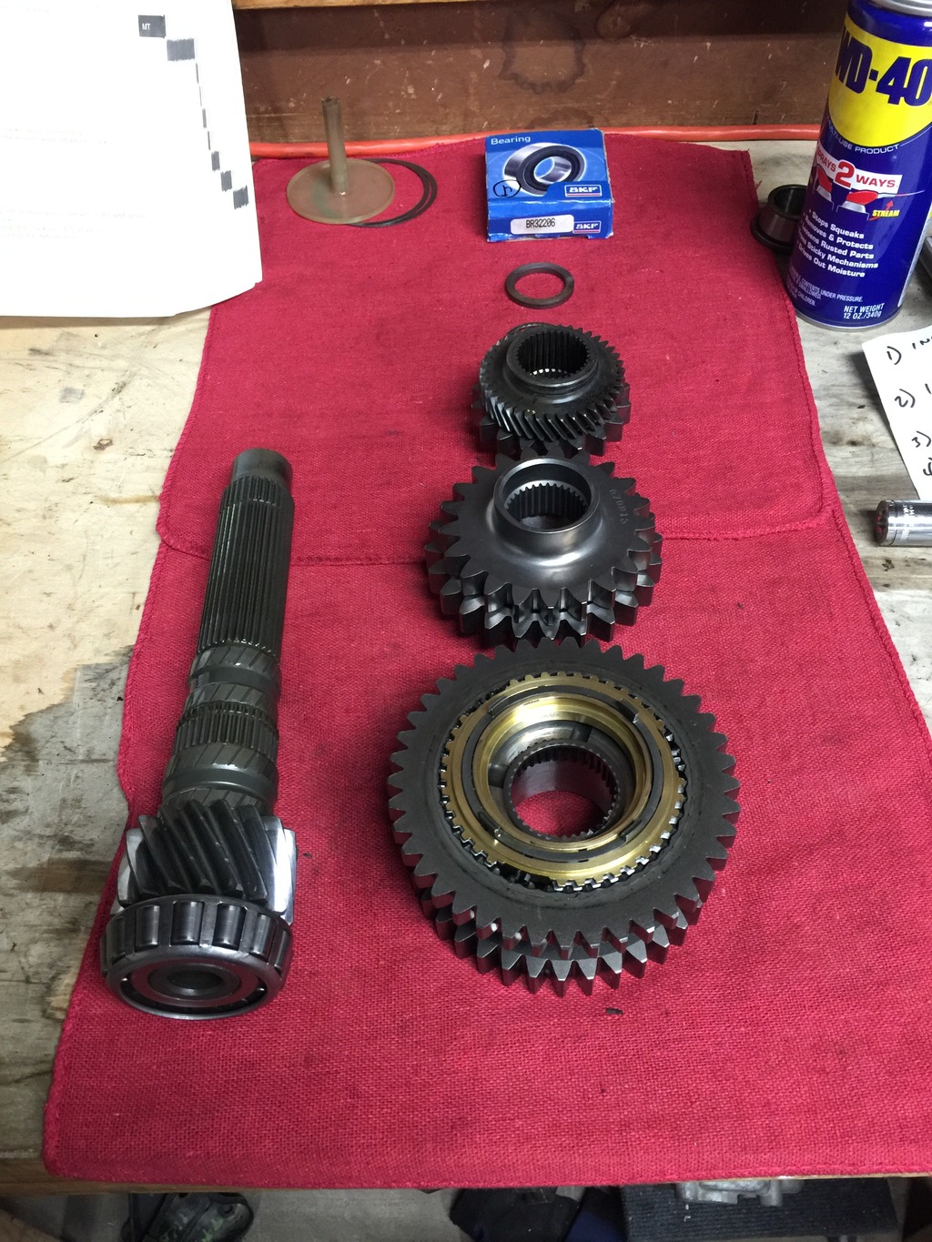
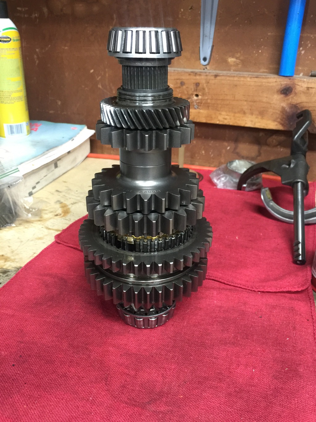
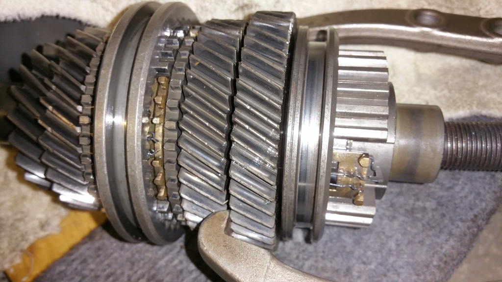
Spent this past weekend putting it all together and all the GTiR stuff fits like a glove, just as Haysam assured me. Here�s how the PAR stuff looked the day it arrived on Labor Day:
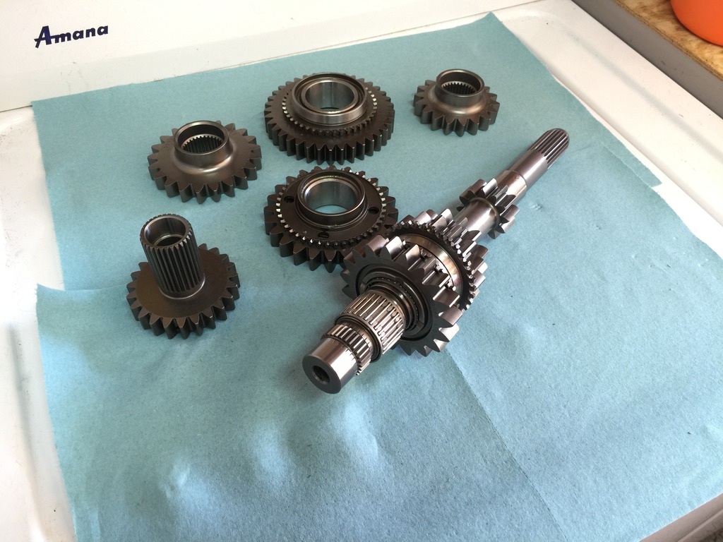
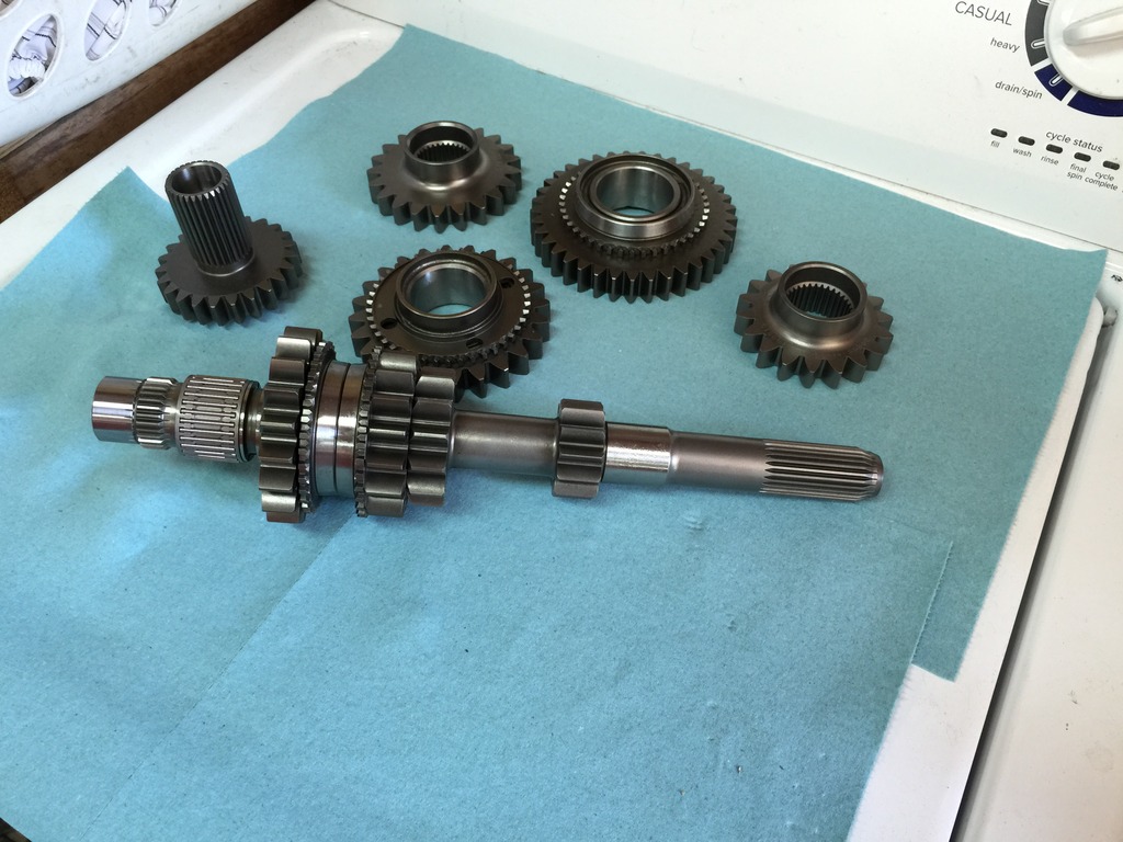
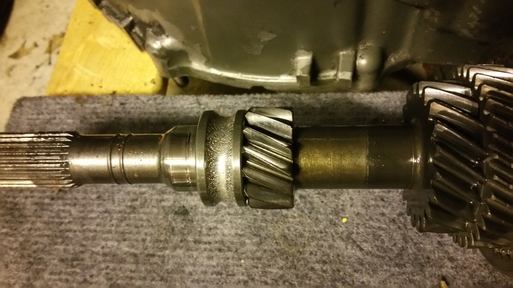
As you can see, in addition to the 1-4 gears, PAR also sends a complete new beefed up input shaft. PAR�s beefed up input shaft has needle rollers for 3rd, 4th, and 5th unlike stock.
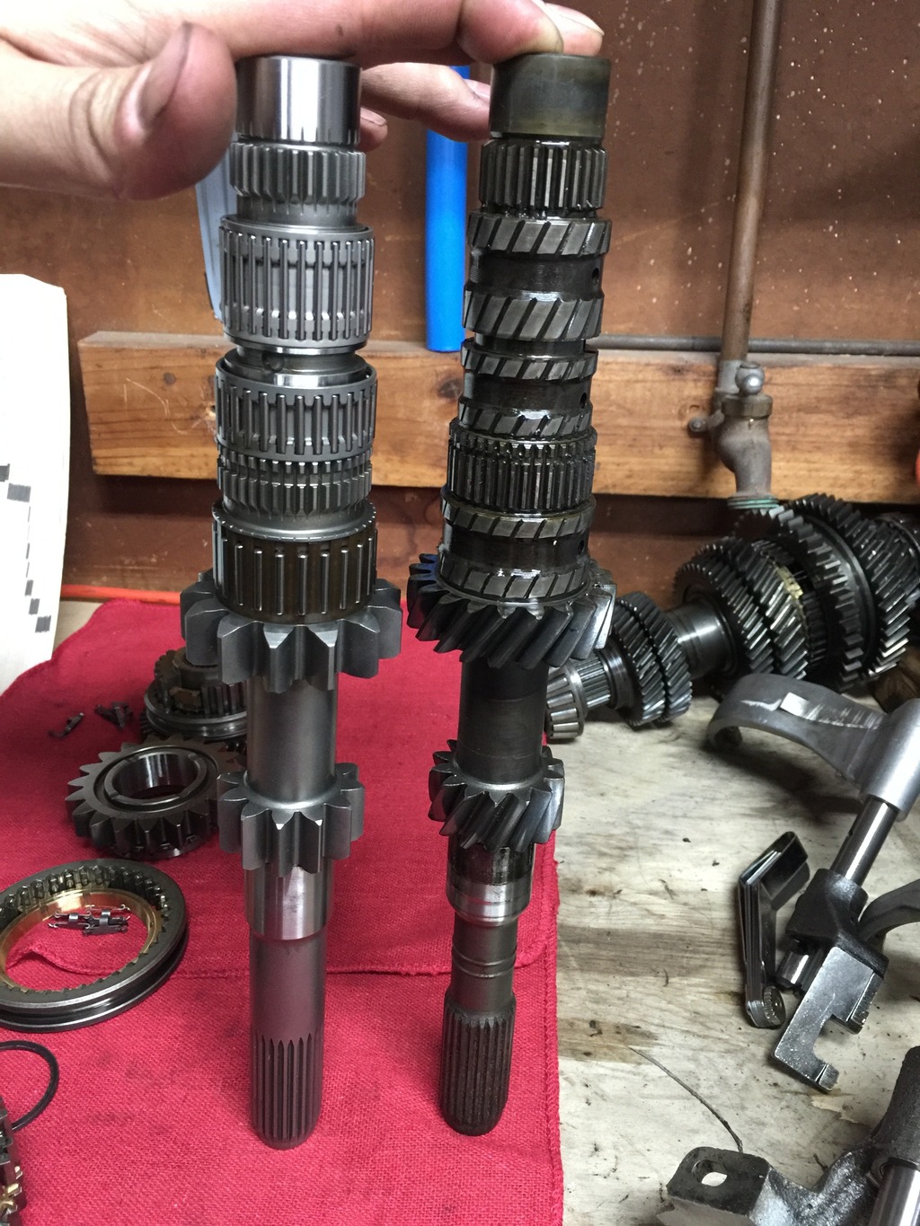
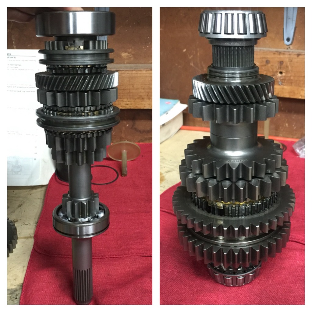
PAR input shaft on the left, OEM on the right:
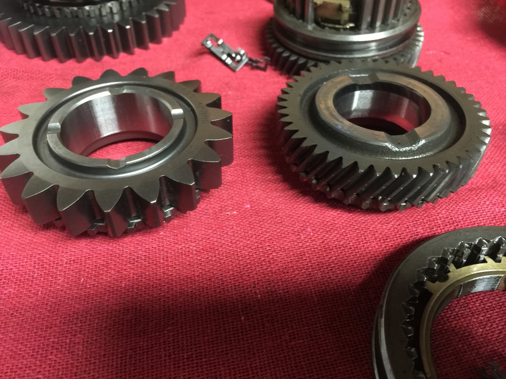
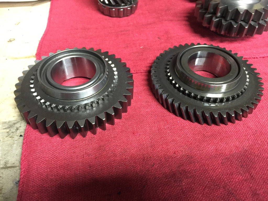
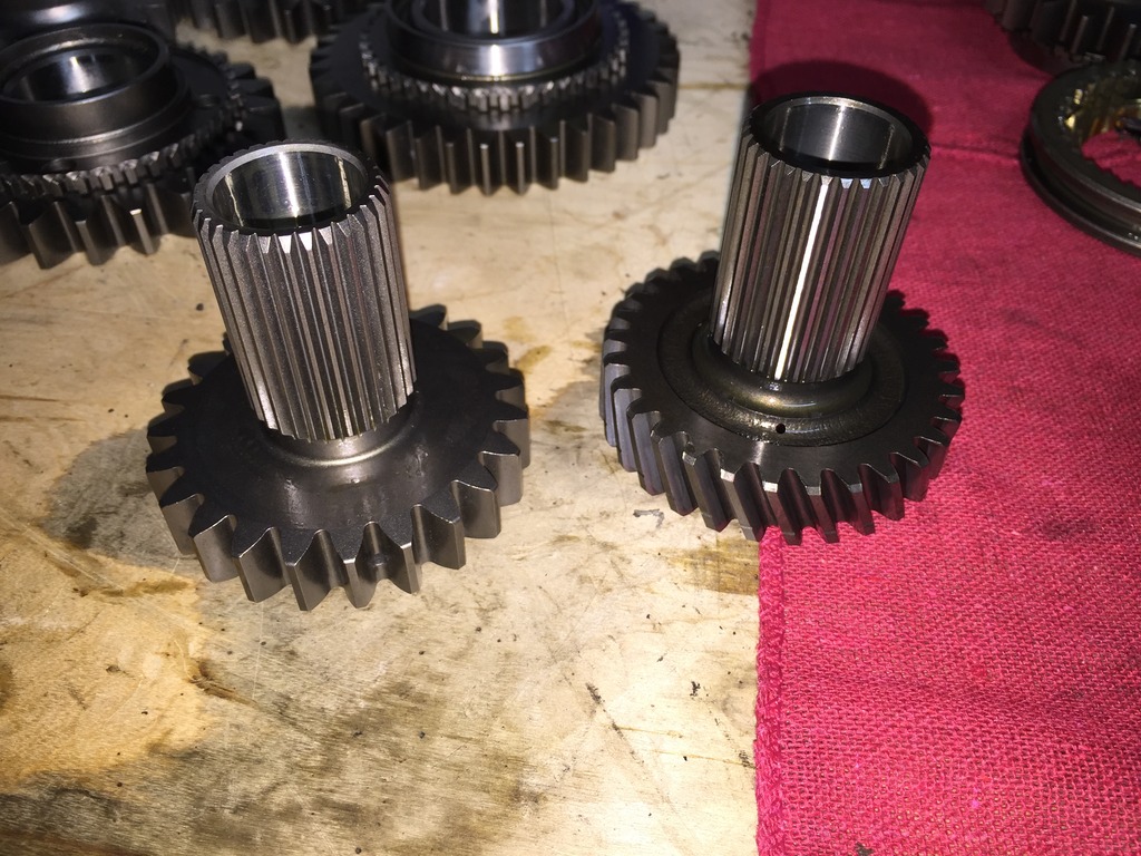
Onto the actual gears (obviously, input 1st and 2nd are already on the input shaft itself, and keeping factory 5th so no 5th gear comparison shots) �
PAR (left) vs OEM 4th input gear:
PAR (left) vs OEM 3rd input gear:
PAR (left) vs OEM 4th main gear:
PAR (left) vs OEM 3rd main gear:
PAR (left) vs OEM 2nd main gear:
PAR (left) vs OEM 1st main gear:
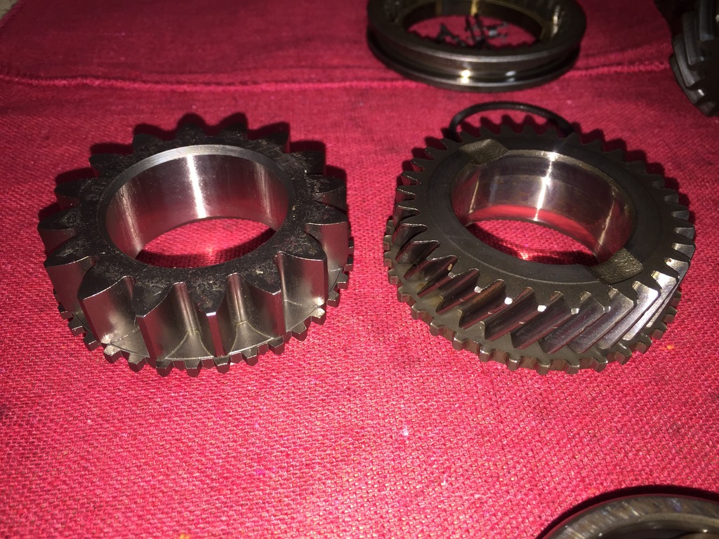
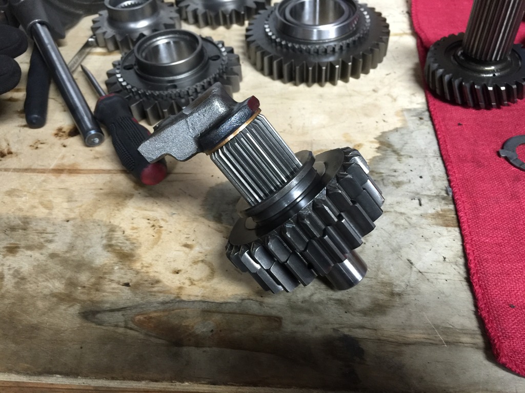
PAR (left) vs OEM reverse:
Complete reverse/idler setup assembled:
I ordered a complete rebuild kit (all seals, bearings, synchros) from American Powertrain Warehouse. I�m very impressed with this kit, it was only $230 shipped and much to my surprise some of the synchros were OEM Nissan still in Nissan packaging. All of the bearings were identical to the OEM units � legit Japanese Nachi, etc. I priced all of these parts from Nissan (again, keep in mind these are the IDENTICAL bearings to Nissan) and it was $625 from Nissan for everything American Powertrain Warehouse sent me.
Their RS5F50V kit for the VE is part number BK182EWS and even includes the strike rod seal, axle seals and input shaft seal.
Surprisingly, I was able to do the entire job using just my press, the $30 �large� bearing splitter from Harbor Freight (which I already had and have used a bunch of times previously and am shocked it hasn't broken on me yet), and some combinations of a normal large 2 jaw puller and an old school ball joint/tie rod separator.
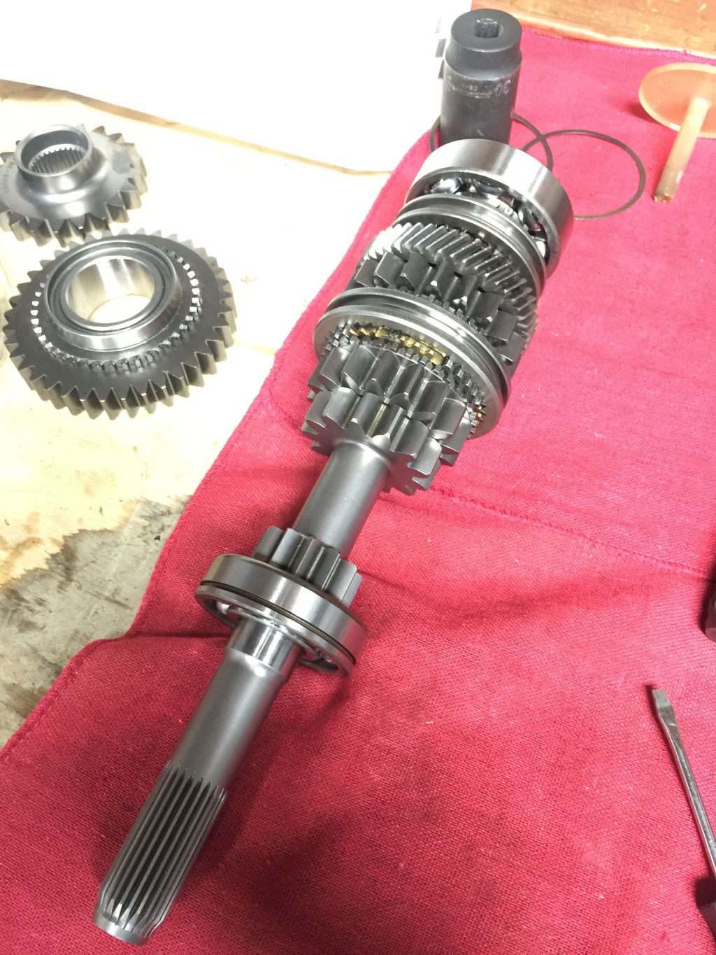
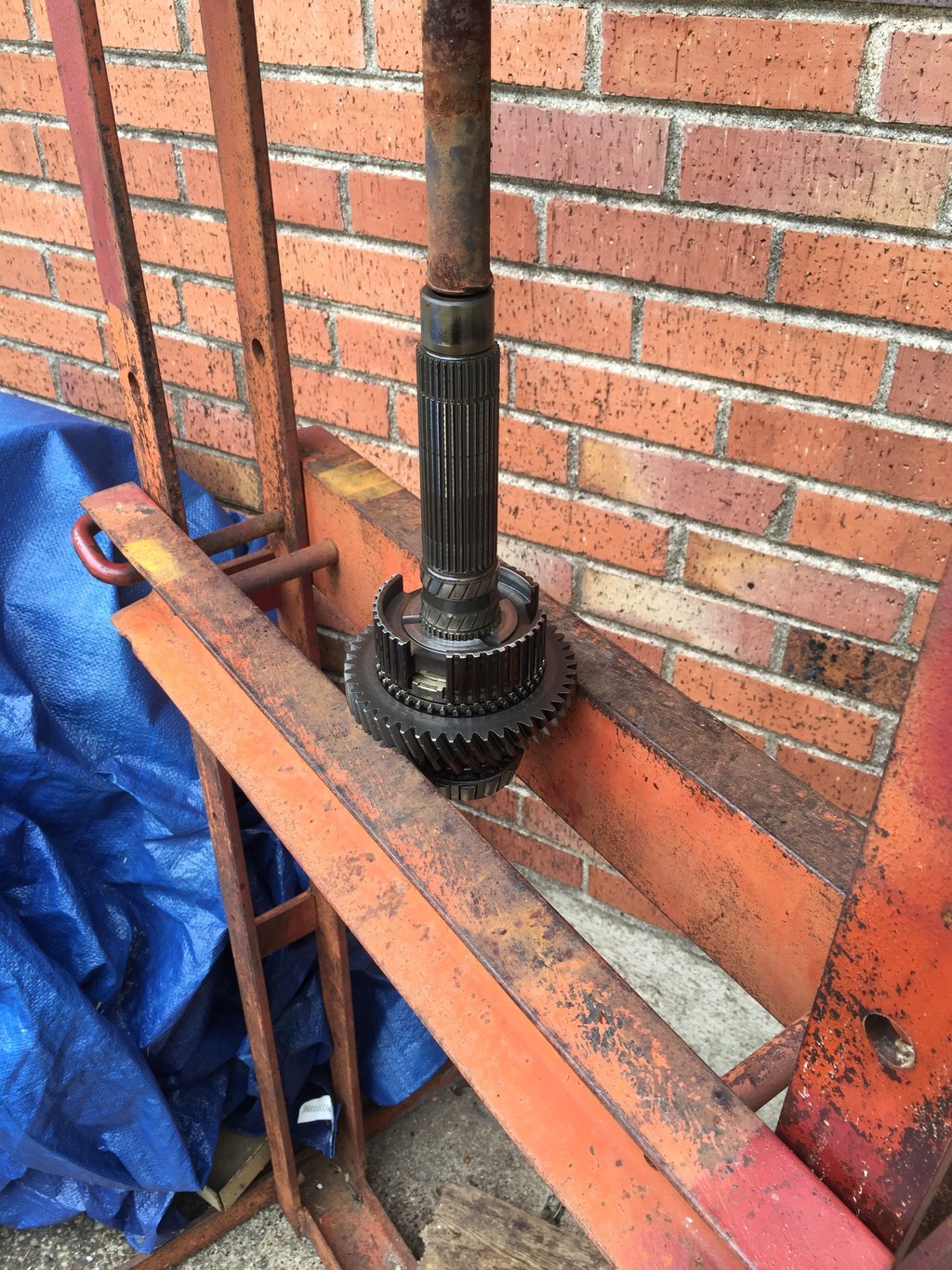
Here are some pics of the process, starting on the input shaft �
Removing old rear input shaft bearing:
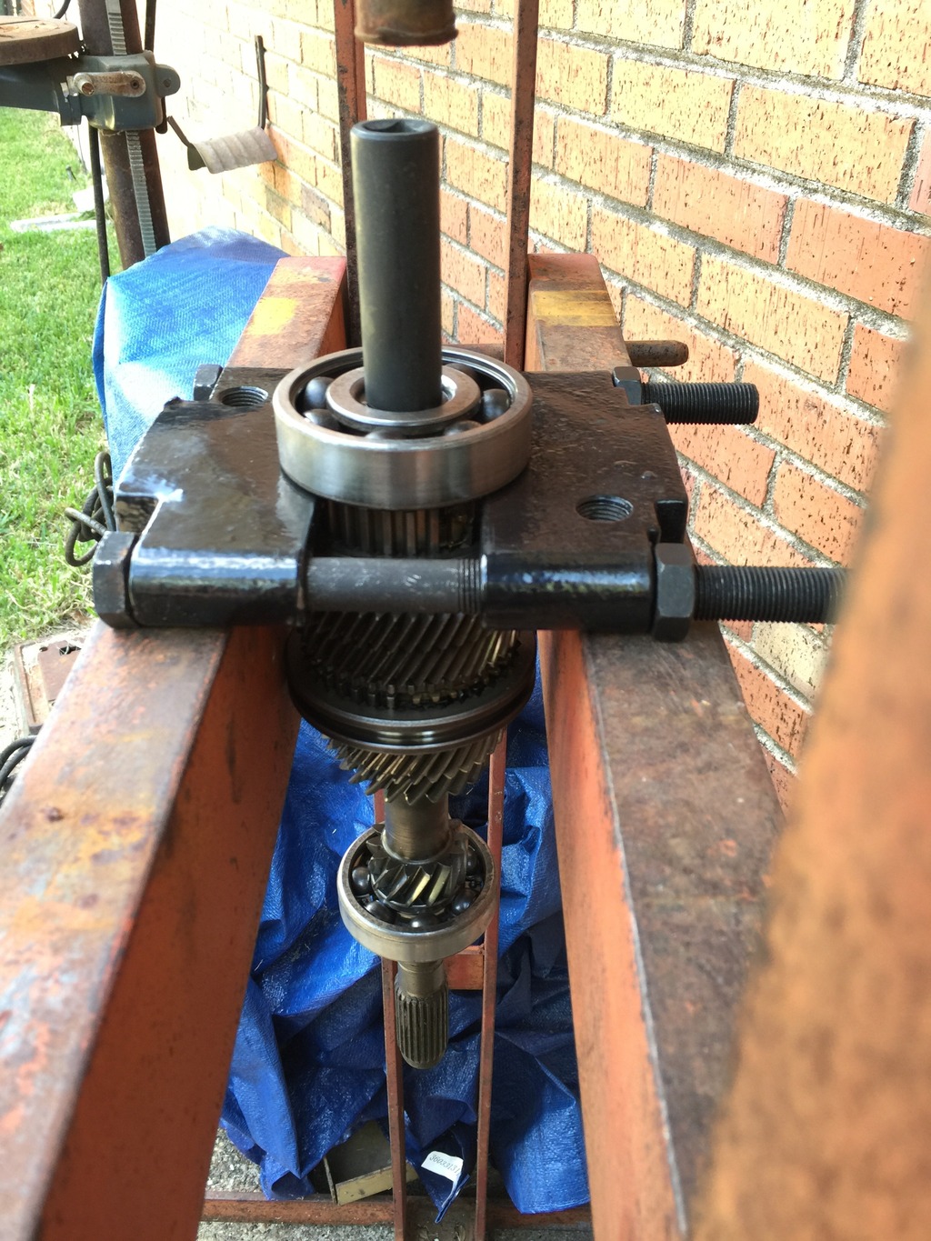
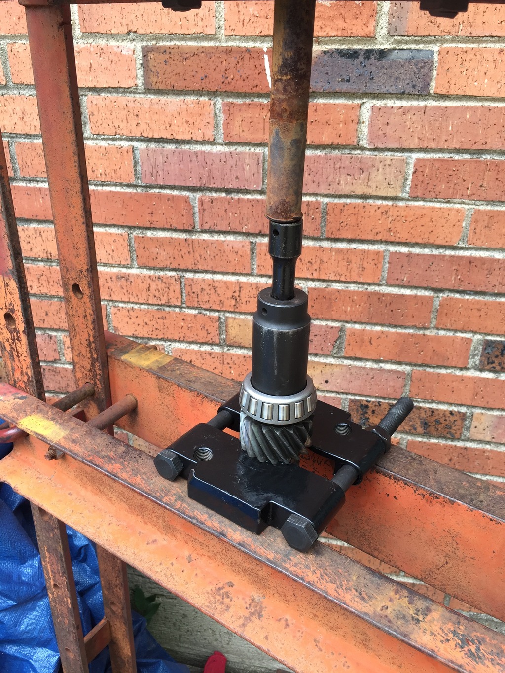
5th gear and synchro hub deal removed (4th gear just slides off after this):
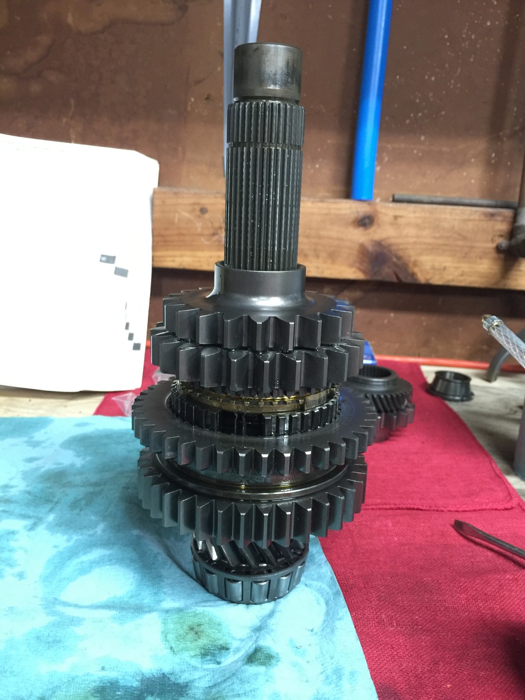
3rd gear removal:
No pics of front input shaft bearing removal but it pressed off easy. Everything removed:
New PAR input shaft laid out with new synchros/bearings ready to go on (everything here went on real easy and didn�t even need the press except for the bearings):
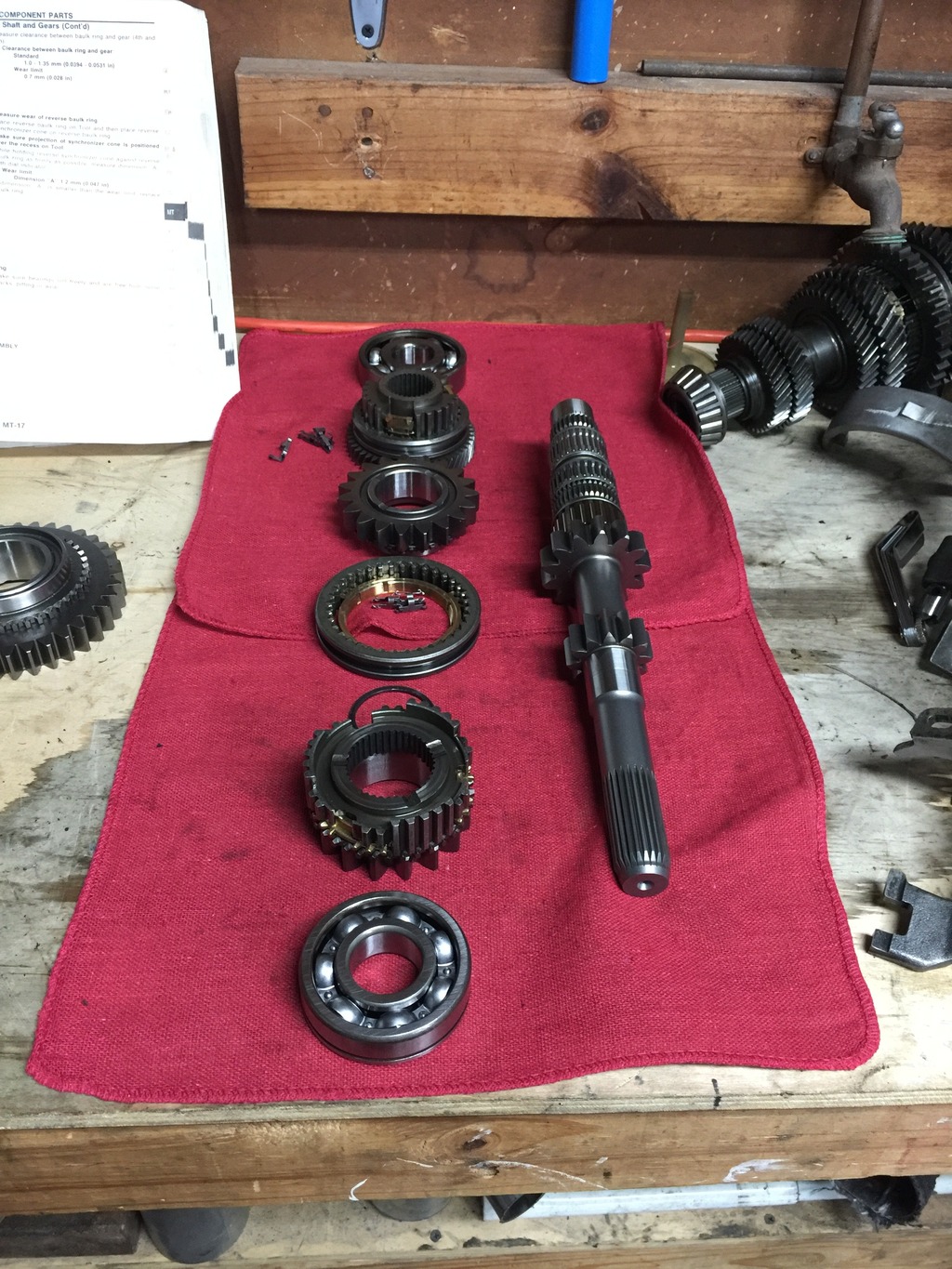
Everything installed and rear input shaft bearing pressed on :
(to be continued in next post)
The VE 5 speed had the RS5F50V transmission - V indicating locking differential.
The 4th gen and 5th gen Maxima 5 speed had the RS5F50A transmission - A indicating open differential. It's my understanding the Canadian spec 4th gen had the RS5F50V and that it was an option on USDM Infiniti I30's.
It's long been assumed that the 3rd, 4th, and 5th gens had identical transmission internals but with different bellhousings and transmission cases.
Anyway -
As some of you probably know, my blue VE is boosted and I cracked a ringland last year. So I put the car down while I rebuilt the engine. I finished my engine rebuild a couple months back - forged internals and the works. I'm going for much higher (and more reliable) power this time. So to match my new stout engine I've been looking into beefing up the transmission for about 6 months now.
Having said all that, the RS5F50A/V is used in a lot of global Nissan cars as well. The GTiR is a very popularly modded car in Australia and there is huge aftermarket support for it over there. Several companies make built gearsets for the GTiR - particularly PPG and PAR Engineering.
Because of that, it's been a well known and long time mod here - particularly for the boosted 4th gen guys - to swap in beefed up aftermarket 3rd and 4th gears designed for the GTiR. Unfortunately, the entire gearset wasn't a swap because the GTiR and Maxima have different reverse gear setups meaning if you swapped 1st and 2nd gear for a GTiR into the Maxima, the Maxima would have no reverse.
To solve that lack of reverse issue, a boosted Canadian user here back in 2008 had PAR Engineering build a complete custom ($$$$$) Maxima-specific 1-4 gearset for his 4th gen. This set came with the proper Maxima-specific input shaft that would allow the Maxima to actually have a reverse gear.
So here is where my quest comes in -
Earlier this year, I had been reading up on old bookmarked threads, scouring the interwebz, etc to confirm that the 3rd gen and 4th/5th gen share identical internals so I could see about beefing up my VE 5 speed transmission. As stated it's long been assumed the 3rd and 4th gen share identical transmissions other than the case and bellhousing.
I pulled up parts diagrams for the 3rd gen, 4th gen, and 5th gen and compared them all with their part numbers side by side by side.
It turns out the 3rd gen is identical to the 4th/5th gen EXCEPT for the reverse gear setup. Everything else between 3rd, 4th, and 5th gen 5 speeds appears to use identical part numbers. The 3rd gen has two reverse idler gears, whereas the 4th/5th gen only has one. Interestingly, the GTiR also has two reverse idler gears - which is the sole reason the entire GTiR setup will NOT work on the 4th/5th gen.
So of course this got me wondering how similar the 3rd gen and GTiR might be.
I cracked open my one of my spare VE 5 speed transmissions and took about a gazillion detailed photos of it and e-mailed the photos to Haysam at PAR who was able to confirm that the VE 5 speed and GTiR share identical internals!
Now why is this cool? This is cool because this means us 3rd gen guys can use OFF THE SHELF complete GTiR gearsets from PAR, PPG, or even Quaife, and not have to deal with prohibitively expensive custom one-off designs. Of course, many would say even off-the-shelf gearsets are prohibitively expensive. These gearsets are about twice the cost of shop rebuilds ($3k). So I guess one way to look at it is that if you blow up your stock transmission while boosted and require 2 or more rebuilds that these built gearsets will have paid for themselves. At least, that's how I'm justifying it lol.
Fast forward to now and I have bought a complete off the shelf straight-cut synchromesh 1-4 GTiR gearset from PAR in Australia (just a hair over $3k shipped right now with the exchange rate - considerably LESS expensive than it used to be). After some debate back and forth I decided to go with the straight cut and keep factory 5th gear � the helical cut gears tend to just send all the forces outwards to the case which makes you prone to breaking the transmission case itself, and keeping factory 5th gear means I won�t have annoying gear whine while cruising. It actually took 3 full months from the date I paid/ordered to arrival at my door � because even though it was an �off the shelf� item, I still had to wait in their production queue.
Spent this past weekend putting it all together and all the GTiR stuff fits like a glove, just as Haysam assured me. Here�s how the PAR stuff looked the day it arrived on Labor Day:


As you can see, in addition to the 1-4 gears, PAR also sends a complete new beefed up input shaft. PAR�s beefed up input shaft has needle rollers for 3rd, 4th, and 5th unlike stock.
PAR input shaft on the left, OEM on the right:

Onto the actual gears (obviously, input 1st and 2nd are already on the input shaft itself, and keeping factory 5th so no 5th gear comparison shots) �
PAR (left) vs OEM 4th input gear:

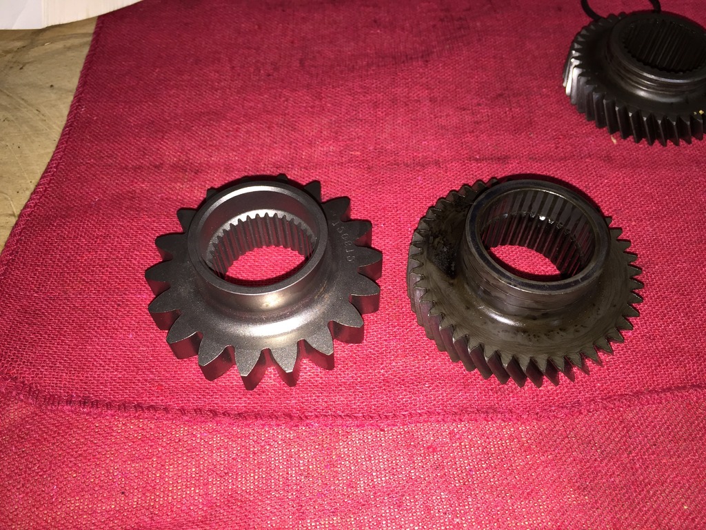
PAR (left) vs OEM 3rd input gear:

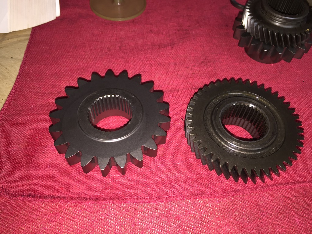
PAR (left) vs OEM 4th main gear:

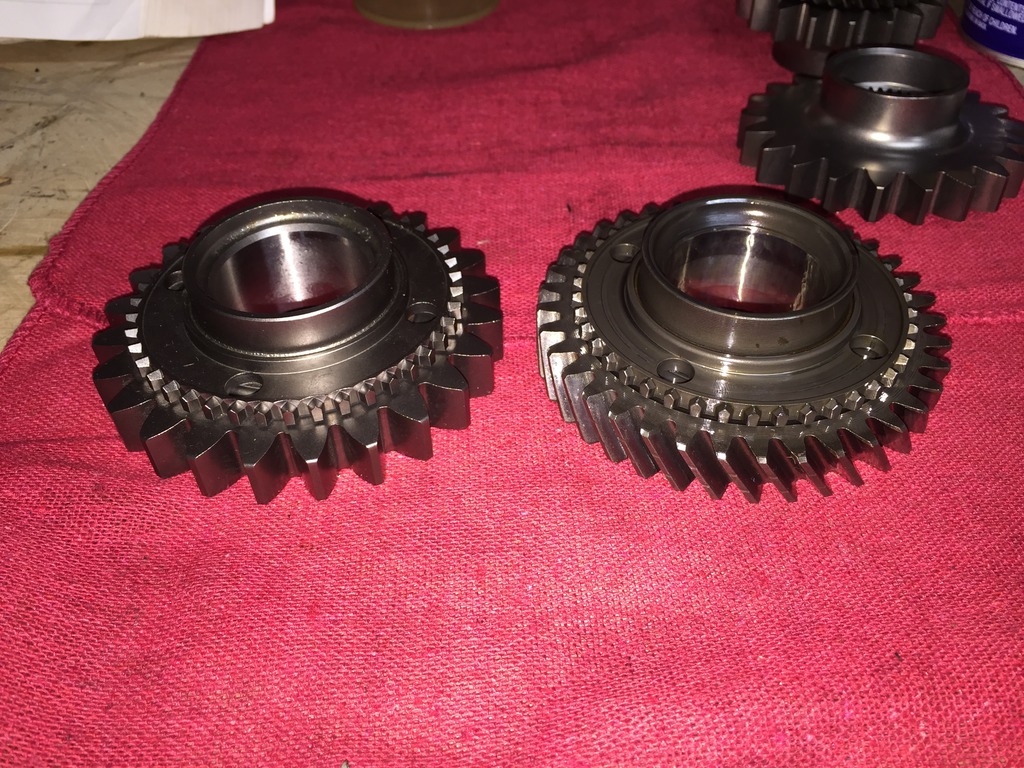
PAR (left) vs OEM 3rd main gear:

PAR (left) vs OEM 2nd main gear:

PAR (left) vs OEM 1st main gear:

PAR (left) vs OEM reverse:

Complete reverse/idler setup assembled:

I ordered a complete rebuild kit (all seals, bearings, synchros) from American Powertrain Warehouse. I�m very impressed with this kit, it was only $230 shipped and much to my surprise some of the synchros were OEM Nissan still in Nissan packaging. All of the bearings were identical to the OEM units � legit Japanese Nachi, etc. I priced all of these parts from Nissan (again, keep in mind these are the IDENTICAL bearings to Nissan) and it was $625 from Nissan for everything American Powertrain Warehouse sent me.
Their RS5F50V kit for the VE is part number BK182EWS and even includes the strike rod seal, axle seals and input shaft seal.
Surprisingly, I was able to do the entire job using just my press, the $30 �large� bearing splitter from Harbor Freight (which I already had and have used a bunch of times previously and am shocked it hasn't broken on me yet), and some combinations of a normal large 2 jaw puller and an old school ball joint/tie rod separator.
Here are some pics of the process, starting on the input shaft �
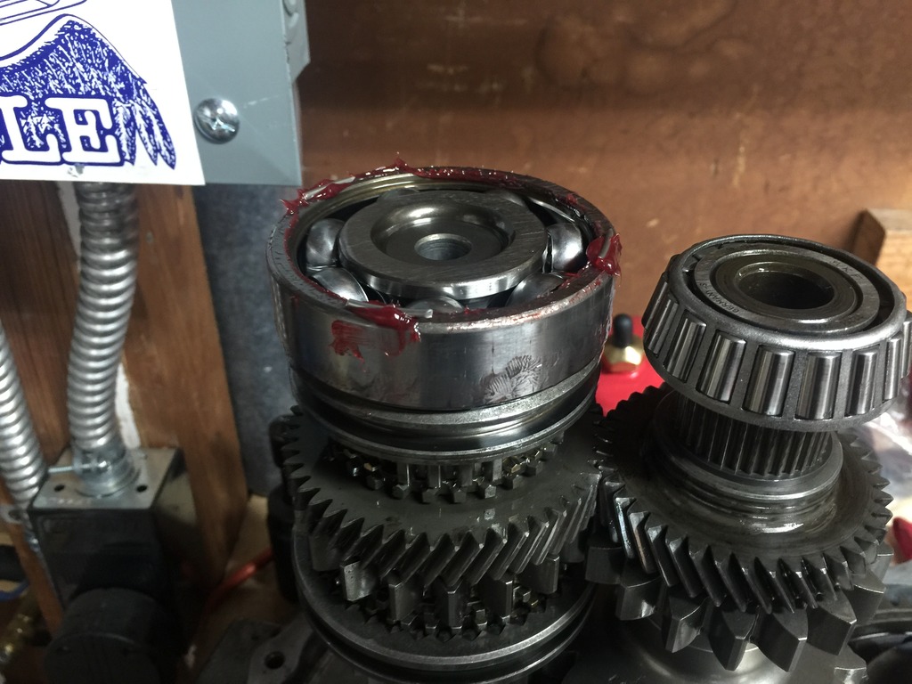
Removing old rear input shaft bearing:


5th gear and synchro hub deal removed (4th gear just slides off after this):

3rd gear removal:


No pics of front input shaft bearing removal but it pressed off easy. Everything removed:

New PAR input shaft laid out with new synchros/bearings ready to go on (everything here went on real easy and didn�t even need the press except for the bearings):

Everything installed and rear input shaft bearing pressed on :

(to be continued in next post)
 09-22-2015, 10:49 AM
#2
2 VE's are better than one!
Thread Starter
iTrader: (31)
Join Date: Sep 2000
Location: Dallas
Posts: 7,358
Pressing on front input shaft bearing:
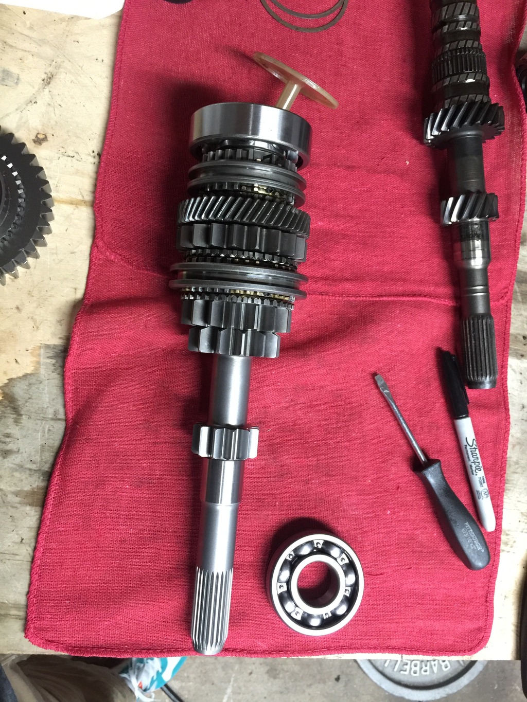
Input shaft totally assembled:
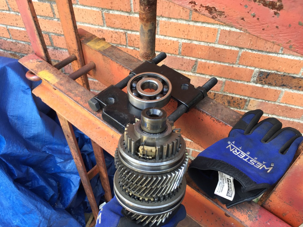
Now onto the main shaft. This was a lot more difficult. Primarily because the whole thing assembled is wider than the support bars on my press so I didn’t have the benefit of being able to face it either direction like on the input shaft in order to press things the direction I needed to press them. At first I tried cutting off the rear main shaft bearing but that was a no go.
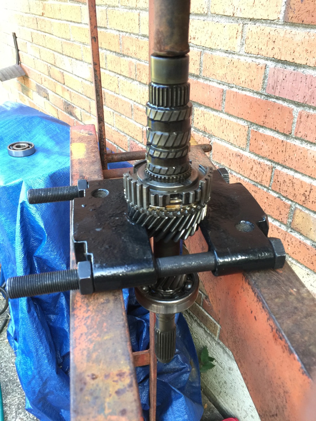
I ended up finding this old ball joint/tie rod tool that I assume my dad used for his shop 30-40 years ago. It worked like a charm along with my vise to pull the rear main shaft bearing:
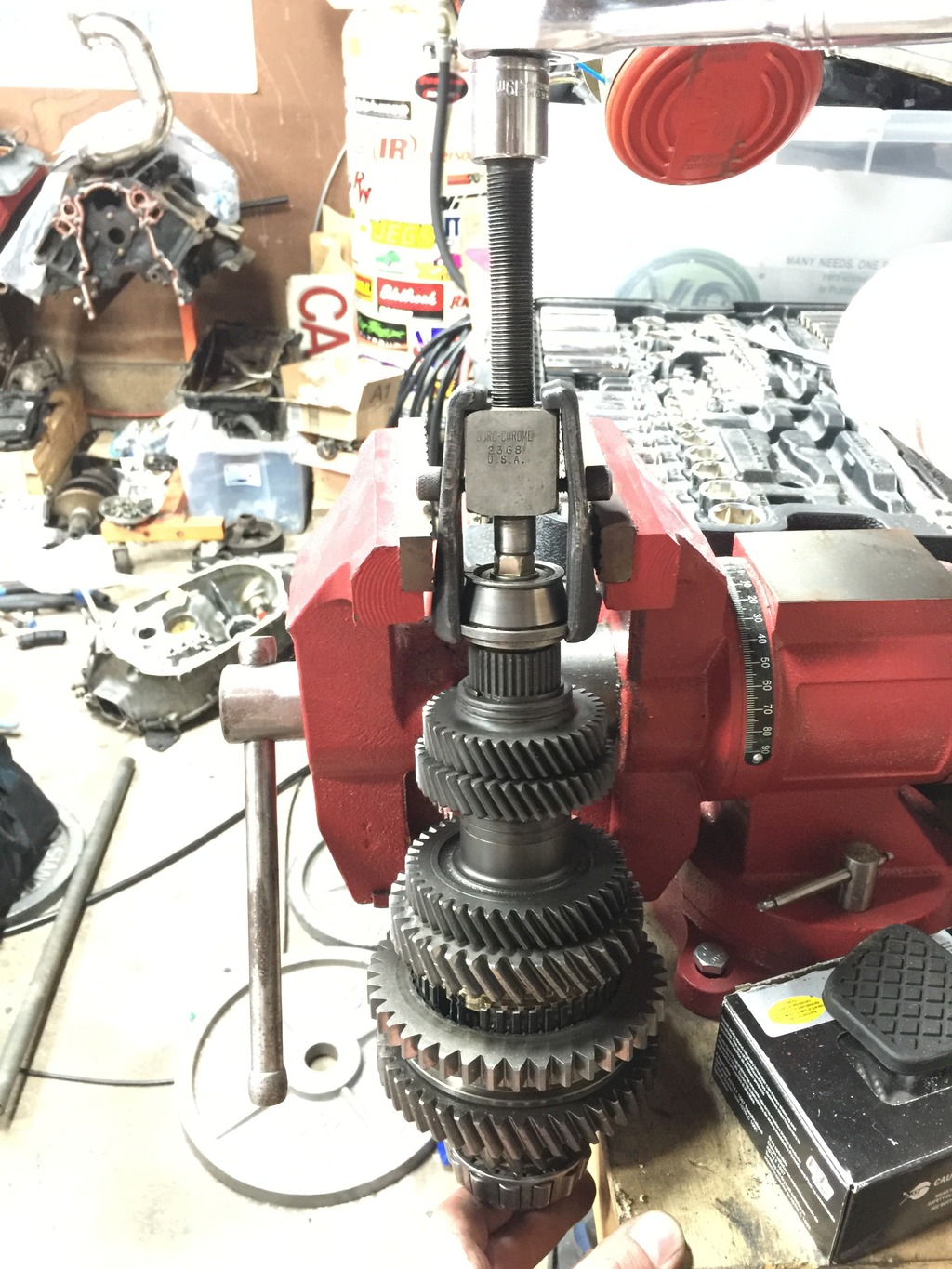
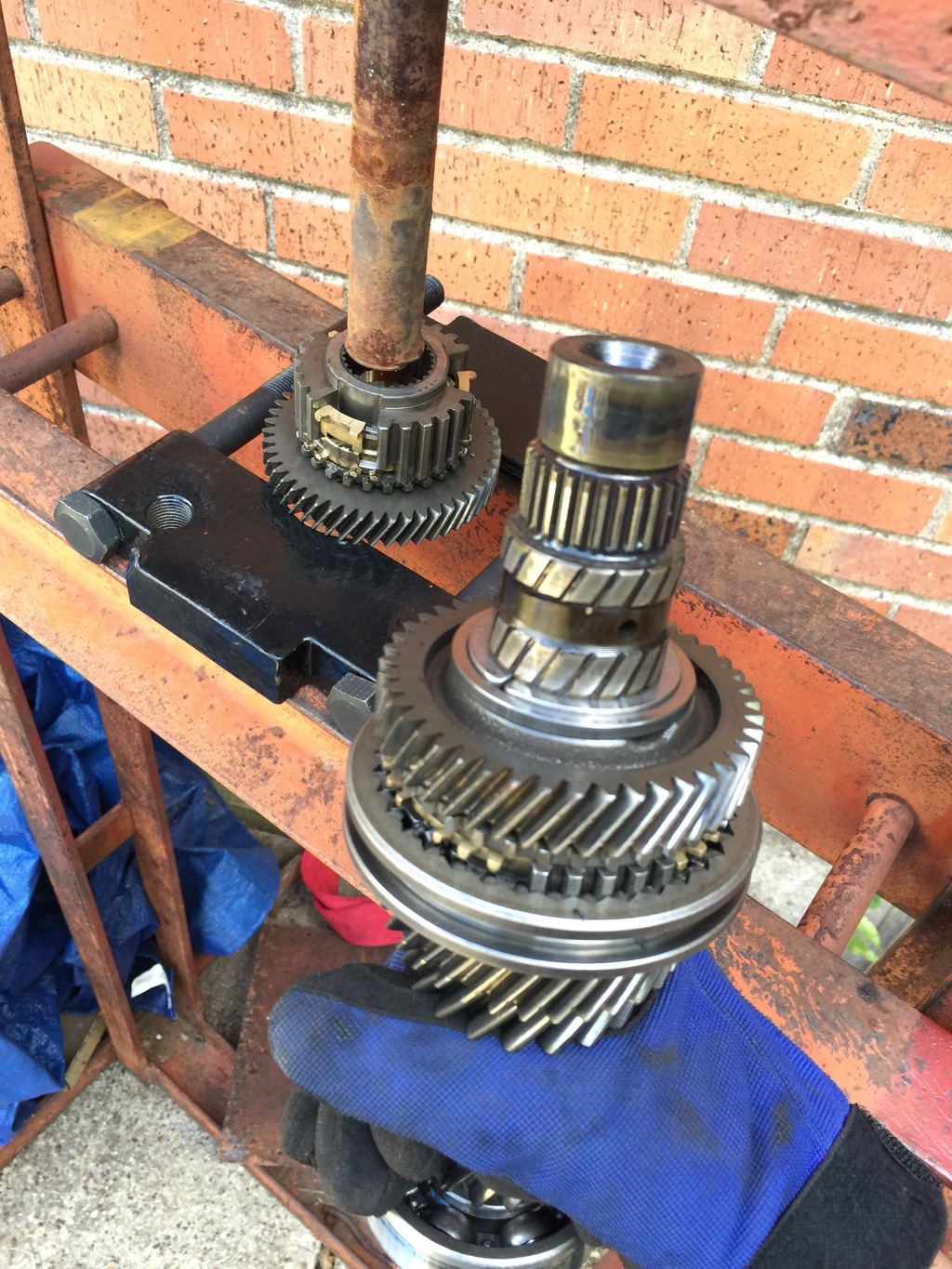
Pulling off 4th and 5th main shaft gears:
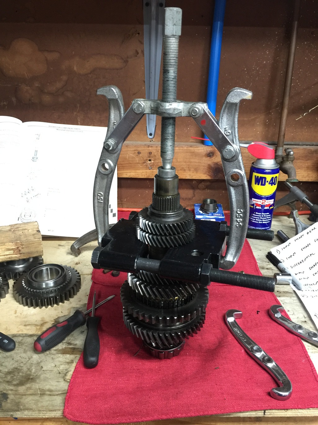
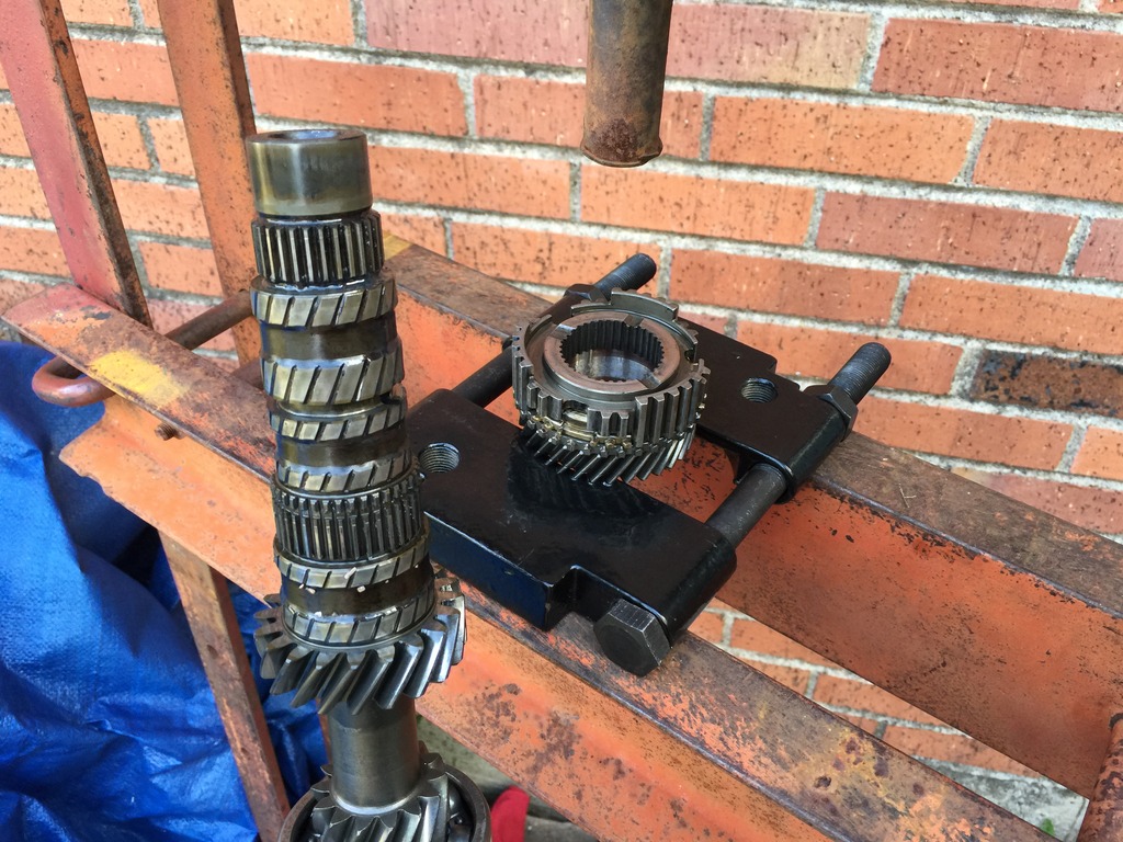
Pulling off 2nd and 3rd main shaft gears:
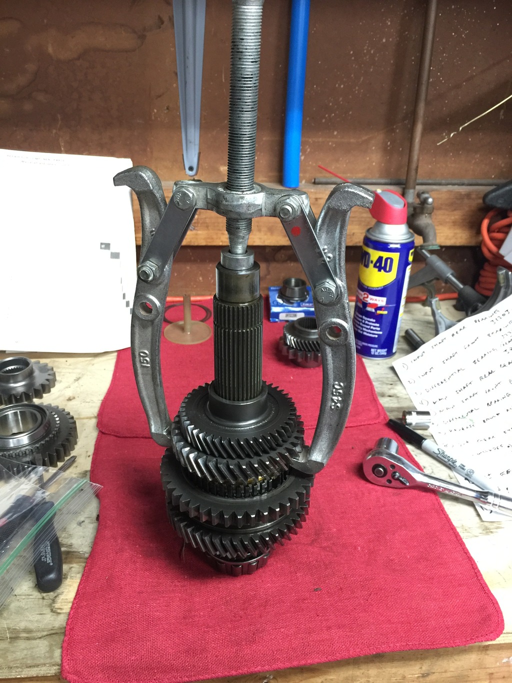
Removing 1st gear and synchro hub deal (thankfully this was a perfect fit on the press support bars!):
Everything pulled off except the front main bearing (the bearing splitter I used for everything else worked to pull this bearing too but I guess I failed to take a picture):
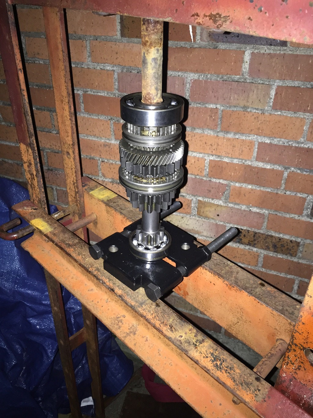
Installing main shaft front bearing:
Pressing the new PAR main gears to my OEM main shaft proved to be fairly difficult. 1st and 2nd gear just slide right on obviously.
Getting 3rd on was a different story. It was very tight to press on. At first I thought maybe I had failed to line it up properly on the splines and was just mashing them together and had an “oh crap” moment. But I triple checked and it was really just that tight.
Anyway, this was getting into Sunday evening by now and the bottle jack on my press totally failed on me in the middle of pressing 3rd gear on (granted the jack was 30+ years old). So I had to stop everything and run to Harbor Freight and thankfully they had ONE 20 ton bottle jack in stock.
After getting home and setting my press up with the new jack I was able to press 3rd on:
Then got 4th, 5th and the rear main shaft bearing pressed on too (no pics of this process, but same as pressing the other gears). All finished:
Finished input and main shafts side by side:
This coming weekend if I have time I’m going to replace the differential bearings and then measure everything for necessary clearance/shims and get those ordered from Nissan and put this sucker back together.

Input shaft totally assembled:

Now onto the main shaft. This was a lot more difficult. Primarily because the whole thing assembled is wider than the support bars on my press so I didn’t have the benefit of being able to face it either direction like on the input shaft in order to press things the direction I needed to press them. At first I tried cutting off the rear main shaft bearing but that was a no go.
I ended up finding this old ball joint/tie rod tool that I assume my dad used for his shop 30-40 years ago. It worked like a charm along with my vise to pull the rear main shaft bearing:

Pulling off 4th and 5th main shaft gears:

Pulling off 2nd and 3rd main shaft gears:

Removing 1st gear and synchro hub deal (thankfully this was a perfect fit on the press support bars!):

Everything pulled off except the front main bearing (the bearing splitter I used for everything else worked to pull this bearing too but I guess I failed to take a picture):

Installing main shaft front bearing:

Pressing the new PAR main gears to my OEM main shaft proved to be fairly difficult. 1st and 2nd gear just slide right on obviously.
Getting 3rd on was a different story. It was very tight to press on. At first I thought maybe I had failed to line it up properly on the splines and was just mashing them together and had an “oh crap” moment. But I triple checked and it was really just that tight.
Anyway, this was getting into Sunday evening by now and the bottle jack on my press totally failed on me in the middle of pressing 3rd gear on (granted the jack was 30+ years old). So I had to stop everything and run to Harbor Freight and thankfully they had ONE 20 ton bottle jack in stock.
After getting home and setting my press up with the new jack I was able to press 3rd on:

Then got 4th, 5th and the rear main shaft bearing pressed on too (no pics of this process, but same as pressing the other gears). All finished:

Finished input and main shafts side by side:

This coming weekend if I have time I’m going to replace the differential bearings and then measure everything for necessary clearance/shims and get those ordered from Nissan and put this sucker back together.
 09-22-2015, 12:37 PM
#4
2 VE's are better than one!
Thread Starter
iTrader: (31)
Join Date: Sep 2000
Location: Dallas
Posts: 7,358
I forgot to add some more details about this PAR gearset. I will have slightly different gear ratios with this setup:
OEM VE 5 speed ratios:
1st - 3.285
2nd - 1.85
3rd - 1.2
4th - .954
5th - .075
PAR GTiR ratios (and these may match the actual GTiR ratios for all I know):
1st - 3.08
2nd - 1.85
3rd - 1.31
4th - .95
5th - stock (.075)
So, as you can see I will now actually have a taller first gear. Third gear will be ever so slightly shorter. Being boosted, with the propensity to blow through 1st gear in a heartbeat, I actually welcome the taller first gear
09-22-2015, 01:29 PM
#5
brahhhhh...that tranny is going to whineeeee like you're in reverse 24/7...but awesome build man.
i have a VLSD in pieces too and just got the bearings from the same place as you.
i was told that the shims are on virtual forever back order from nissan...sooo before i rip the bearings and races off i want to make sure i can find the shims. i started digging into mcmaster and they do have shims...so i gotta measure and see what dia and thickness i'll need.
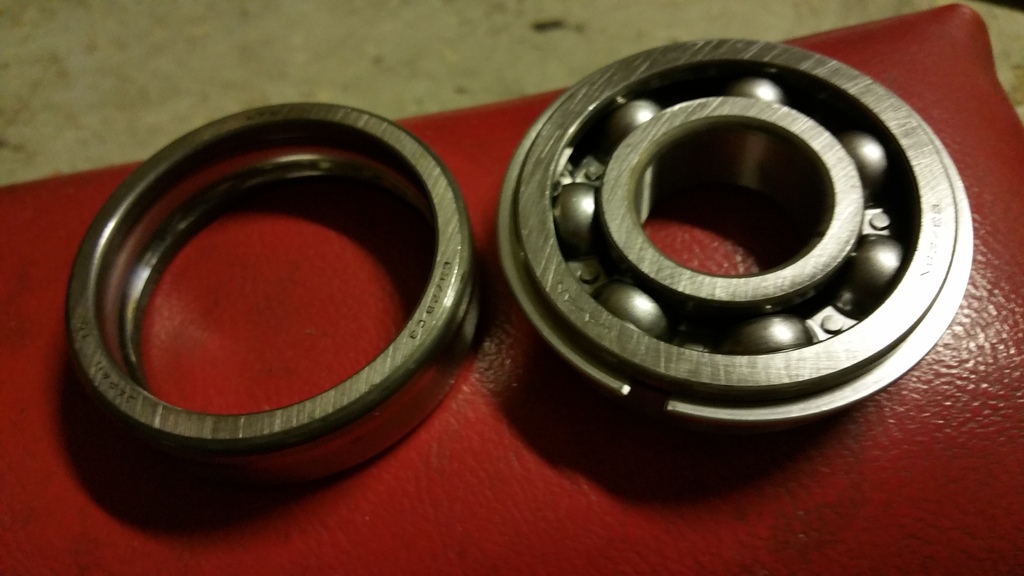
looks like you get the same input shaft bearing with the snap ring on it too. i was like wtf is this extra piece??
i have a VLSD in pieces too and just got the bearings from the same place as you.
i was told that the shims are on virtual forever back order from nissan...sooo before i rip the bearings and races off i want to make sure i can find the shims. i started digging into mcmaster and they do have shims...so i gotta measure and see what dia and thickness i'll need.
looks like you get the same input shaft bearing with the snap ring on it too. i was like wtf is this extra piece??
09-22-2015, 02:16 PM
#6
2 VE's are better than one!
Thread Starter
iTrader: (31)
Join Date: Sep 2000
Location: Dallas
Posts: 7,358
Haysam at PAR was actually strongly encouraging the straight cut, and told me that their "new technology" manufacturing practices on their straight cut gears are actually surprisingly quiet. He said my exhaust will almost surely be louder than the gears. In fact, he said many ricers actually are DISAPPOINTED in how (relatively) quiet they are and complain they aren't loud enough! It was unbeknownst to me until I started researching into this stuff online that a lot of ricers actually seek out and desire loud straight cut gear whine.

So I ended up figuring that having some 1-4 whine is better than having to potentially tear everything back down later on over a cracked case. l purposely kept factory 5th though so that once I'm in 5th/cruising/daily driving it should be totally quiet.
i have a VLSD in pieces too and just got the bearings from the same place as you.
i was told that the shims are on virtual forever back order from nissan...sooo before i rip the bearings and races off i want to make sure i can find the shims. i started digging into mcmaster and they do have shims...so i gotta measure and see what dia and thickness i'll need.
looks like you get the same input shaft bearing with the snap ring on it too. i was like wtf is this extra piece??
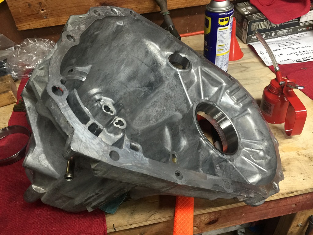
The transmission I'm using for this build is one I had rebuilt here locally about 10 years ago ($1,200) on my original black VE 5 speed. Stupidly, I managed to crack the bell-housing on it when I was re-installing it one day for some reason (I started tightening down one of the bolts not realizing the dowel wasn't totally lined up)
 and it cracked right across the bellhousing.
So it's been sitting on a shelf for years ever since. I actually bought a replacement bellhousing for it years ago from somebody here, nearly certain it was CapedCadaver but can't remember 100%. So I'm actually piecing this all together between my old transmission and Caped's parts he sent me. The old synchros and stuff I pulled out had noooo noticeable wear or anything on them though, so the shop must have at least replaced those on the rebuild I mention above. I did notice the main shaft bearings had NO shims whatsoever though. I wonder if it really truly didn't need them or if the place that rebuilt this trans back 10 years ago was just lazy. I'm betting on the latter.
I really bet 9 times out of 10, when people pay for a rebuild at a shop, the shop literally only replaces just the bad/broken part and slaps it back together.
I hope I don't run into a forever wait on shims. You got any links or part numbers handy for the McMaster shims? I have a buddy into domestic stuff and he assures me that universal shim "kits" are somewhat universally available but I haven't really stumbled across any.
They sent you an actual snap ring with that front input shaft bearing? They didn't send me a ring, but I did notice the groove in the bearing unlike the OEM one. I wasn't quite sure what to make of it and figured it's somewhat irrelevant. I just positioned the bearing with the stamped text of the race facing the same was as the old one
 09-22-2015, 06:31 PM
#7
Yeah the shims are more or less universal. They are there to reduce slack on the bearing and more or less set the preload on them. Let me go measure the shim diameter and see what they have. Go to McMaster and search for bearing shim and from a quick search I see sizes 2 inches or larger so maybe there's hope.
I'll be honest I'm not sure I want to dump so much more cash into the car. Getting tired of it and getting too old to be tooling around. The other downer is I take mass transit more so I barely get to drive it. Years ago I drove to work everyday.
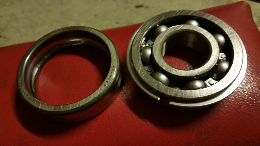
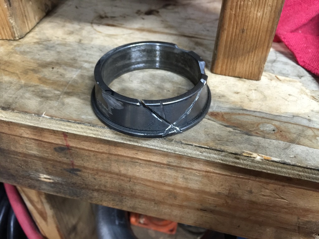
Here's the snap ring they left on mine. The other one is more or less what's left of the old bearings.
I'll be honest I'm not sure I want to dump so much more cash into the car. Getting tired of it and getting too old to be tooling around. The other downer is I take mass transit more so I barely get to drive it. Years ago I drove to work everyday.
Here's the snap ring they left on mine. The other one is more or less what's left of the old bearings.
 09-22-2015, 07:24 PM
#8
2 VE's are better than one!
Thread Starter
iTrader: (31)
Join Date: Sep 2000
Location: Dallas
Posts: 7,358
Yeah the shims are more or less universal. They are there to reduce slack on the bearing and more or less set the preload on them. Let me go measure the shim diameter and see what they have. Go to McMaster and search for bearing shim and from a quick search I see sizes 2 inches or larger so maybe there's hope.
I'll be honest I'm not sure I want to dump so much more cash into the car. Getting tired of it and getting too old to be tooling around. The other downer is I take mass transit more so I barely get to drive it. Years ago I drove to work everyday.
Here's the snap ring they left on mine. The other one is more or less what's left of the old bearings.
Oh come on, you are never too old. There's an old(er) guy on Garage Journal who is building an AWESOME 1966 Ford truck with a complete modern Ecoboost drivetrain (engine/tranny/compete suspension/frame/everything) swap. He's even swapping in the modern Ford complete dashboard and steering setup and seats and everything. It's crazy impressive, the thread spans 100+ pages and that dude has just gone at it with all sorts of health issues popping up along the way and nearly given up several times. Had to sell off several other projects at various times to fund it too. His work is phenomenal though and he's on the home stretch now.
That's odd about the snap ring. Makes me wonder what other application that exact bearing has which requires the snap ring.
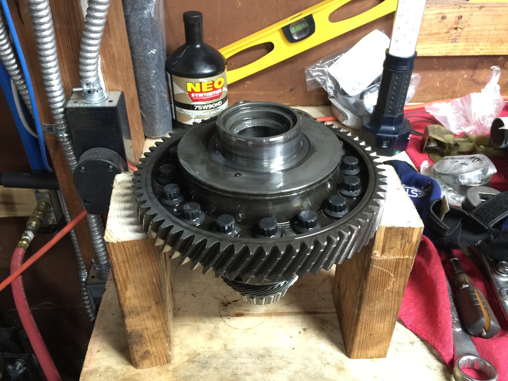
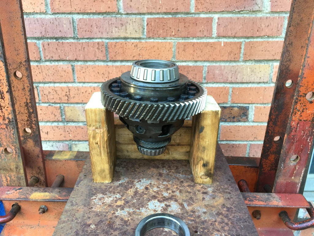
Well I had a few minutes tonight so I worked on the differential some. Only had time to replace the smaller bearing as the larger one is going to require some more effort/time on it (since my bearing splitter doesn't fit under it). I may have to cut it off - I'll have to see this weekend.
Pulling the old one off:

Pressing on the new:

All done:
 09-22-2015, 08:27 PM
#9
LOL...ok you're partially right. just not enough hours in the day. i'm just tired by the end of the day...but the hobby keeps me going.
so i pulled the 5th gear off the input shaft and i slightly chipped one of the corners. probably ok but i guess we'll see...
you happen to have your old gears laying around?
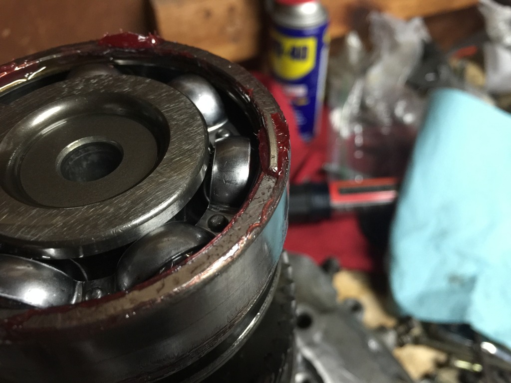
the beeeitoch is trying to get the inner race off the front bearing since...well all i got there is the inner race and there's nothing the puller can grip on to.
there used to be a full bearing here.....
so i pulled the 5th gear off the input shaft and i slightly chipped one of the corners. probably ok but i guess we'll see...
you happen to have your old gears laying around?
the beeeitoch is trying to get the inner race off the front bearing since...well all i got there is the inner race and there's nothing the puller can grip on to.
there used to be a full bearing here.....
09-22-2015, 08:36 PM
#11
also...are you dunking any of the parts into a parts washer or since you're going all new (more or less) you don't really have to worry too much about it?
edit - just noticed you're re-using your 5th gear...ahhh i should be ok. tiny chip at a corner.
i was going to go w/o swapping syncros and just do the bearing but the syncros on 3rd and 4th were pretty busted out soooo....just put in an order for it. hopefully it'll get here soon and i can at least finish the input shaft by next week. then i'll mess with the main shaft. i just hope i remember how all the pieces of the jig saw puzzle go together.


 09-23-2015, 06:55 AM
#14
2 VE's are better than one!
Thread Starter
iTrader: (31)
Join Date: Sep 2000
Location: Dallas
Posts: 7,358
LOL...ok you're partially right. just not enough hours in the day. i'm just tired by the end of the day...but the hobby keeps me going.
so i pulled the 5th gear off the input shaft and i slightly chipped one of the corners. probably ok but i guess we'll see...
you happen to have your old gears laying around?
the beeeitoch is trying to get the inner race off the front bearing since...well all i got there is the inner race and there's nothing the puller can grip on to.
there used to be a full bearing here.....
Wow that inner race looks trashed. Where's the rest of the bearing? Was it so bad that it fell apart or did you cut it/remove it trying to get it
also...are you dunking any of the parts into a parts washer or since you're going all new (more or less) you don't really have to worry too much about it?
edit - just noticed you're re-using your 5th gear...ahhh i should be ok. tiny chip at a corner.
i was going to go w/o swapping syncros and just do the bearing but the syncros on 3rd and 4th were pretty busted out soooo....just put in an order for it. hopefully it'll get here soon and i can at least finish the input shaft by next week. then i'll mess with the main shaft. i just hope i remember how all the pieces of the jig saw puzzle go together.
edit - just noticed you're re-using your 5th gear...ahhh i should be ok. tiny chip at a corner.
i was going to go w/o swapping syncros and just do the bearing but the syncros on 3rd and 4th were pretty busted out soooo....just put in an order for it. hopefully it'll get here soon and i can at least finish the input shaft by next week. then i'll mess with the main shaft. i just hope i remember how all the pieces of the jig saw puzzle go together.
I have the shafts tucked away right now in a garbage bag and all oiled up. I have been thinking about how to clean it all off again very thoroughly somehow prior to installing it though. I may just spray them all down again and try to get into every nook and cranny with a bunch of brake cleaner - and of course re-oil everything ASAP. Or any other ideas?
I have a gazillion pictures of everything and also have all my old stuff bagged/labeled, so let me know if you need some tips getting everything back in order/facing the correct way/etc.
Really my only hesitancy was that I was somewhat expecting to get into this and then getting stuck needing some specialty Nissan tool. If I knew I could do all of this with tools I've already had all along I would have been doing my own transmission work for years now.
Really the only aggravating part of it is that my press is on the back patio and having to take a gazillion trips back and forth between the garage and the press gets old real quick.

I don't know about "fun" but it is very pleasing that the 3rd gen dual reverse idler gear setup makes using off the shelf GTiR stuff possible.
It kind of makes up for the aftermarket gods frowning upon the 3rd gen all these years whereas everything was seemingly always available for the 4th gens. But really it turns out that all the real big boy parts (at least for the VE) were always available they were just labeled as being for the TTZ (forged rods/pistons/ARP head and main studs) and the GTiR (transmission).
09-23-2015, 07:48 AM
#15
the chip is very small...like 2 grains of sand.
bro the bearing cage (bits of it) was on the magnet. it was missing half the ball bearings. when i pull the input shaft up everything just fell out. that's why you only saw the outer race of the bearing when i took the pic. everything else in the middle of the bearing is floating around or stuck in the magnet.
since i'm reusing most of the stuff i might just dip them in a can of chem dip to clean off the bits of metal and shoot wd40 or some grease. i have this rust preventer spray and it comes out like white lithium grease in a can but it's thinner consistency. as i pulled the gears off i even saw bits of metal from the bearing cage inside the input shaft. so i gotta strip everything out of the case and clean it all out.
09-23-2015, 08:13 AM
#16
2 VE's are better than one!
Thread Starter
iTrader: (31)
Join Date: Sep 2000
Location: Dallas
Posts: 7,358
the chip is very small...like 2 grains of sand.
bro the bearing cage (bits of it) was on the magnet. it was missing half the ball bearings. when i pull the input shaft up everything just fell out. that's why you only saw the outer race of the bearing when i took the pic. everything else in the middle of the bearing is floating around or stuck in the magnet.
since i'm reusing most of the stuff i might just dip them in a can of chem dip to clean off the bits of metal and shoot wd40 or some grease. i have this rust preventer spray and it comes out like white lithium grease in a can but it's thinner consistency. as i pulled the gears off i even saw bits of metal from the bearing cage inside the input shaft. so i gotta strip everything out of the case and clean it all out.
bro the bearing cage (bits of it) was on the magnet. it was missing half the ball bearings. when i pull the input shaft up everything just fell out. that's why you only saw the outer race of the bearing when i took the pic. everything else in the middle of the bearing is floating around or stuck in the magnet.
since i'm reusing most of the stuff i might just dip them in a can of chem dip to clean off the bits of metal and shoot wd40 or some grease. i have this rust preventer spray and it comes out like white lithium grease in a can but it's thinner consistency. as i pulled the gears off i even saw bits of metal from the bearing cage inside the input shaft. so i gotta strip everything out of the case and clean it all out.
09-23-2015, 09:04 AM
#18

Neat thread, i remember when i fubar'd my diff in my 4th gen and used a 3rd gens trans to get another diff. I do remember the 5th gear and reverse was different in the 3rd gens vs the 4ths. So it very well could mean that all of the ppg and par stuff for the GTiR will just drop right in. It will be a great upgrade.
09-24-2015, 12:30 PM
#20
2 VE's are better than one!
Thread Starter
iTrader: (31)
Join Date: Sep 2000
Location: Dallas
Posts: 7,358
Dan and/or Hectic. What say you guys about this part?
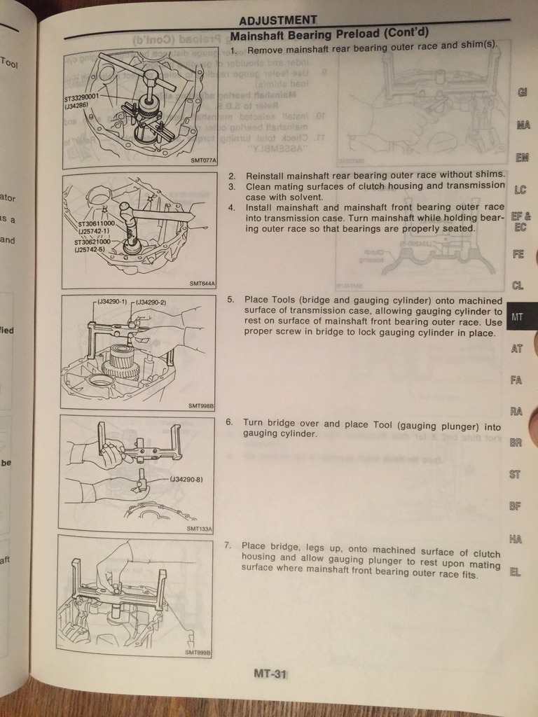
The FSM calls for the use of a specific Kent Moore tool to measure for the mainshaft bearing/preload. It calls for Kent Moore kit # J34290 (sometimes written as J-34290 I've found).
It looks like this is actually a kit that fits many makes/models but the only parts from the kit I need for these Nissans are the "bridge" (J34290-1), the "gauging cylinder" (J34290-2), and only one of the "plungers" (J34290-8).
I've been scouring the interwebz for a couple of days now looking for this part and found an incomplete set on eBay yesterday which I purchased ($44). Here's a picture of it:
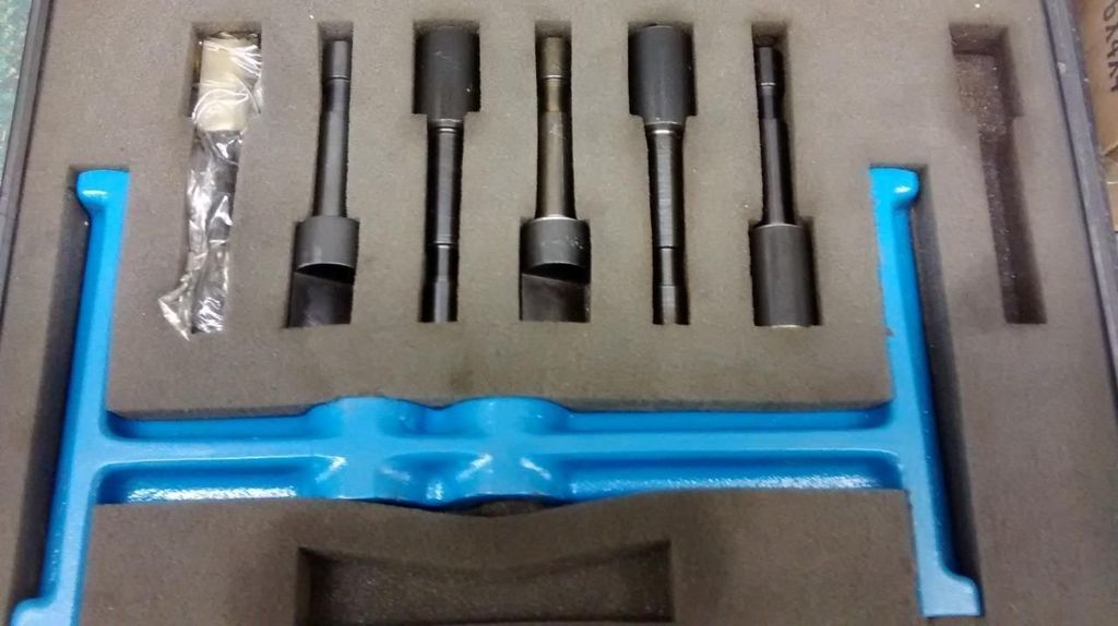
The problem is that it's not complete and I can't get the seller to tell me the part numbers for the ones that are confirmed with the set. I can definitely see that the kit contains the bridge (J34290-1).
I can also tell that it definitely does not appear to contain the gauging cylinder (J34290-2). I'm hoping that of the plungers contained in the kit that one happens to be the one I need (J34290-8). I really don't understand why the seller couldn't have just told me before shipping it - I sent two messages and received zero response to either. It DOES appear that the plunger J34290-8 is still available from some sellers ($100+) so worst case scenario I will purchase just that plunger if it's not in the kit I receive.
However, I'm not sure what to do about the missing gauging cylinder. As far as I can tell/deduce/assume - it's literally just a cylinder that the plunger fits into. Unfortunately it does NOT appear that the gauging cylinder (J34290-2) is still available for purchase separately.
Do you guys think there is any reason I can't just find a cylinder with the appropriate inside and outside diameters and use that?
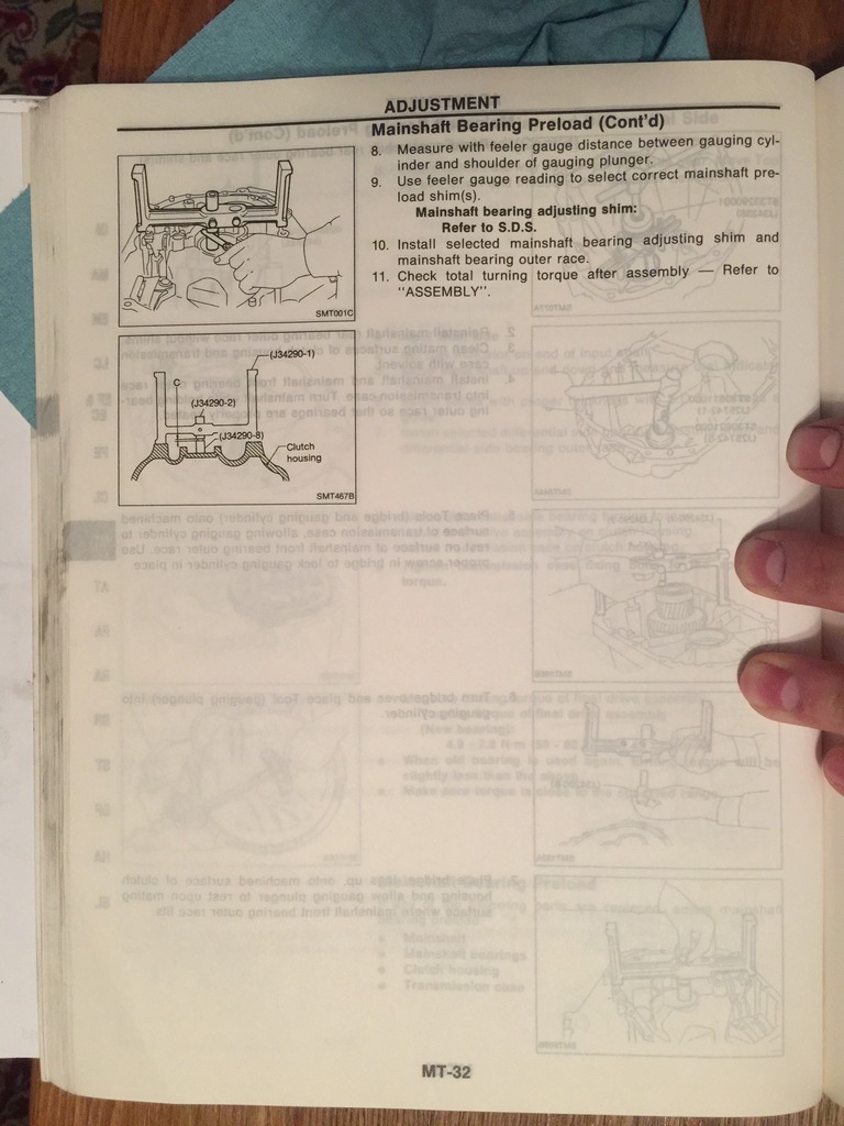
For some reason Nissan only lists out the correct shim sizes/spacing with regard to this specific tool and the distance between the gauging cylinder and the plunger (measure "C" listed on MT-32). So it looks like I definitely need the plunger itself and like I said I will buy it separately if it's not in the set I have coming. I don't understand why Nissan did it this way. It seems like other cars just use a straight edge across the case surface and the manufacturer gives you total X amount and you just subtract/add your measurements to arrive at Y shim. Without knowing the exact dimensions of these tools (or having the tool) it seems impossible to determine the "C" measure I mention above.
But it certainly appears to me that the gauging cylinder itself need not be original. Am I crazy here or can anybody confirm my thinking?
The FSM calls for the use of a specific Kent Moore tool to measure for the mainshaft bearing/preload. It calls for Kent Moore kit # J34290 (sometimes written as J-34290 I've found).
It looks like this is actually a kit that fits many makes/models but the only parts from the kit I need for these Nissans are the "bridge" (J34290-1), the "gauging cylinder" (J34290-2), and only one of the "plungers" (J34290-8).


I've been scouring the interwebz for a couple of days now looking for this part and found an incomplete set on eBay yesterday which I purchased ($44). Here's a picture of it:

The problem is that it's not complete and I can't get the seller to tell me the part numbers for the ones that are confirmed with the set. I can definitely see that the kit contains the bridge (J34290-1).
I can also tell that it definitely does not appear to contain the gauging cylinder (J34290-2). I'm hoping that of the plungers contained in the kit that one happens to be the one I need (J34290-8). I really don't understand why the seller couldn't have just told me before shipping it - I sent two messages and received zero response to either. It DOES appear that the plunger J34290-8 is still available from some sellers ($100+) so worst case scenario I will purchase just that plunger if it's not in the kit I receive.
However, I'm not sure what to do about the missing gauging cylinder. As far as I can tell/deduce/assume - it's literally just a cylinder that the plunger fits into. Unfortunately it does NOT appear that the gauging cylinder (J34290-2) is still available for purchase separately.
Do you guys think there is any reason I can't just find a cylinder with the appropriate inside and outside diameters and use that?
For some reason Nissan only lists out the correct shim sizes/spacing with regard to this specific tool and the distance between the gauging cylinder and the plunger (measure "C" listed on MT-32). So it looks like I definitely need the plunger itself and like I said I will buy it separately if it's not in the set I have coming. I don't understand why Nissan did it this way. It seems like other cars just use a straight edge across the case surface and the manufacturer gives you total X amount and you just subtract/add your measurements to arrive at Y shim. Without knowing the exact dimensions of these tools (or having the tool) it seems impossible to determine the "C" measure I mention above.
But it certainly appears to me that the gauging cylinder itself need not be original. Am I crazy here or can anybody confirm my thinking?
09-24-2015, 04:23 PM
#21
2 VE's are better than one!
Thread Starter
iTrader: (31)
Join Date: Sep 2000
Location: Dallas
Posts: 7,358
Well it just finally dawned on me that I am thinking about this incorrectly. I would for sure need to have (or know the exact length measurement of) the gauging cylinder #J34290-2.
The reason why I can't just use any tube of the correct diameter is because the bridge has to be flipped over, meaning if I just use some tube of arbitrary length that when flipped over, the proper length wouldn't be hanging past the bridge to then measure for the "C" measurement described in the manual. So that sucks because I can't find this gauging cylinder for sale anywhere.
It seems there's got to be some other way to measure this, but the problem is Nissan's specs only list this measurement with the "C" number derived from the Kent Moore tool.
09-24-2015, 04:24 PM
#22
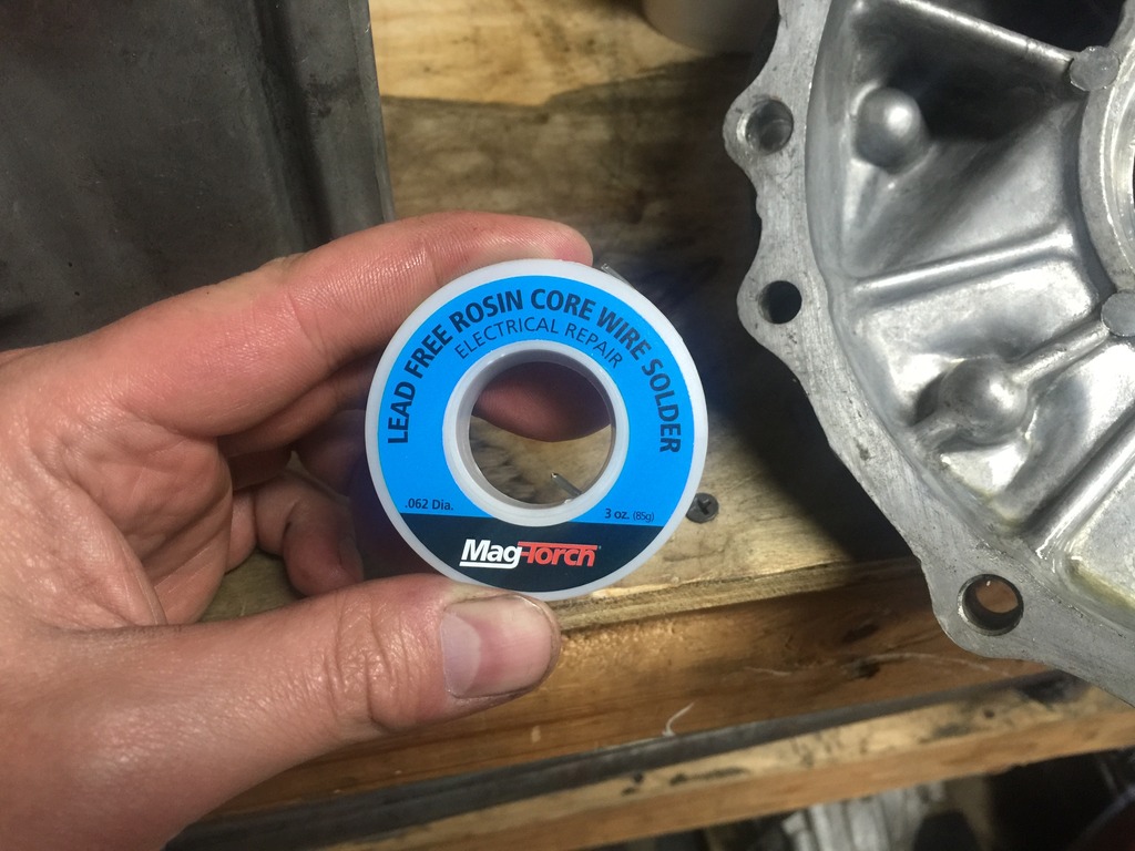
Soooo Nealoc said that you can use the solder crush method. Throw some lead solder behind the race. Clamp in the case torque to spec. Wait a little and then open and measure the crushed solder with a mic. That's your thickness and then look for the shim for the size you need.
09-24-2015, 04:27 PM
#23
Well it just finally dawned on me that I am thinking about this incorrectly. I would for sure need to have (or know the exact length measurement of) the gauging cylinder #J34290-2.
The reason why I can't just use any tube of the correct diameter is because the bridge has to be flipped over, meaning if I just use some tube of arbitrary length that when flipped over, the proper length wouldn't be hanging past the bridge to then measure for the "C" measurement described in the manual. So that sucks because I can't find this gauging cylinder for sale anywhere.
It seems there's got to be some other way to measure this, but the problem is Nissan's specs only list this measurement with the "C" number derived from the Kent Moore tool.
The reason why I can't just use any tube of the correct diameter is because the bridge has to be flipped over, meaning if I just use some tube of arbitrary length that when flipped over, the proper length wouldn't be hanging past the bridge to then measure for the "C" measurement described in the manual. So that sucks because I can't find this gauging cylinder for sale anywhere.
It seems there's got to be some other way to measure this, but the problem is Nissan's specs only list this measurement with the "C" number derived from the Kent Moore tool.
09-24-2015, 05:02 PM
#24
2 VE's are better than one!
Thread Starter
iTrader: (31)
Join Date: Sep 2000
Location: Dallas
Posts: 7,358
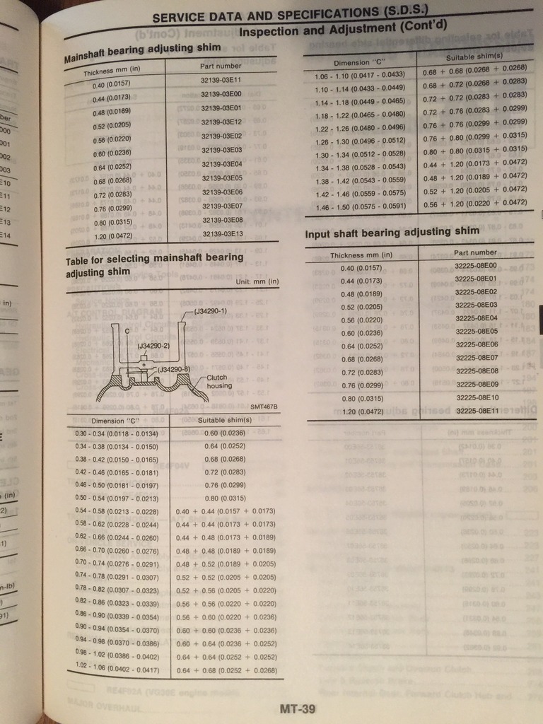
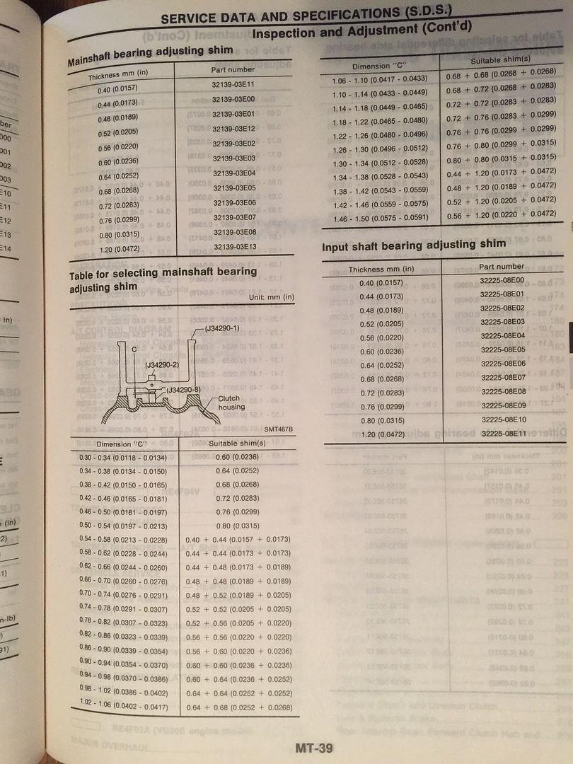
Unless it's listed somewhere else the only guide for shim selection that we have for the mainshaft is this page, and every shim described here only correlates with "C"
So with that solder crush method, are we saying that the thickness of the crushed solder = the "C" measurement and then order a shim per the FSM specs? Or are we saying forget the "C" measurement, and whatever thickness the crushed solder is to just get a shim in that exact thickness?

So with that solder crush method, are we saying that the thickness of the crushed solder = the "C" measurement and then order a shim per the FSM specs? Or are we saying forget the "C" measurement, and whatever thickness the crushed solder is to just get a shim in that exact thickness?
09-24-2015, 07:25 PM
#25
Unless it's listed somewhere else the only guide for shim selection that we have for the mainshaft is this page, and every shim described here only correlates with "C"
So with that solder crush method, are we saying that the thickness of the crushed solder = the "C" measurement and then order a shim per the FSM specs? Or are we saying forget the "C" measurement, and whatever thickness the crushed solder is to just get a shim in that exact thickness?
So with that solder crush method, are we saying that the thickness of the crushed solder = the "C" measurement and then order a shim per the FSM specs? Or are we saying forget the "C" measurement, and whatever thickness the crushed solder is to just get a shim in that exact thickness?
 09-24-2015, 08:03 PM
#27
2 VE's are better than one!
Thread Starter
iTrader: (31)
Join Date: Sep 2000
Location: Dallas
Posts: 7,358
Although I would think that if the bearing presses on nice and snug there's probably nothing to worry about? It's not like there's any movement there, all that part needs to do is have the bearing press onto it.
 09-25-2015, 03:27 AM
#30
This goes right along with the wheel bearing discussion. As far as I'm concerned, some marring where the bearing was pressed on is completely acceptable, or at least personally does not lead me hunting for a new input shaft or a new wheel hub in the case of wheel bearings. Honestly I have always viewed it as normal and thought not much of it. Which is why I asked for pictures of those hubs, to compare it with what I have seen and reused without problems.
I find alternatives to procedures in the service manual that references Kent Moore or dealer specific tools, I have never checked that mainshaft preload specification. I usually replace the weak link which is of course the input shaft bearing, any damaged gears, had a cracked bellhousing once, seals and close it up. Sounds like you are spending a load of money on this build man. I hope that Pulsar input shaft helps to stabilize things in there and extend the lifespan of the front bearing. It is the exact same as the stock one correct? That SKF is Korean correct? I got one of those from McGuire several years ago that I used on a 4th gen box. As far as the ISB goes, I can't hurt to try different manufacturers. Might actually be better off.
I find alternatives to procedures in the service manual that references Kent Moore or dealer specific tools, I have never checked that mainshaft preload specification. I usually replace the weak link which is of course the input shaft bearing, any damaged gears, had a cracked bellhousing once, seals and close it up. Sounds like you are spending a load of money on this build man. I hope that Pulsar input shaft helps to stabilize things in there and extend the lifespan of the front bearing. It is the exact same as the stock one correct? That SKF is Korean correct? I got one of those from McGuire several years ago that I used on a 4th gen box. As far as the ISB goes, I can't hurt to try different manufacturers. Might actually be better off.
09-25-2015, 06:07 AM
#31
2 VE's are better than one!
Thread Starter
iTrader: (31)
Join Date: Sep 2000
Location: Dallas
Posts: 7,358
I find alternatives to procedures in the service manual that references Kent Moore or dealer specific tools, I have never checked that mainshaft preload specification. I usually replace the weak link which is of course the input shaft bearing, any damaged gears, had a cracked bellhousing once, seals and close it up. Sounds like you are spending a load of money on this build man. I hope that Pulsar input shaft helps to stabilize things in there and extend the lifespan of the front bearing. It is the exact same as the stock one correct? That SKF is Korean correct? I got one of those from McGuire several years ago that I used on a 4th gen box. As far as the ISB goes, I can't hurt to try different manufacturers. Might actually be better off.
It's interesting that this transmission I'm rebuilding now has no shims on it whatsoever anywhere other than the input shaft rear bearing. None anywhere else. I'm really starting to think that most likely even "professionals" don't bother shimming the mainshaft stuff or much of anything really. Not that that makes it the right thing to do. I mean a shop only needs it to last long enough to not fail during the 6 or 12 month warranty period.
When researching this, it appears that the 4th gen guys especially for some reason seem to blow through bearings. They consider it a massive weak point of the transmission. I don't seem to recall ever seeing/hearing as much complaint from the 3rd gen guys about it though. I've never had one "fail" on me and I've rocked four separate 5 speed transmissions over the past decade plus. Is that what you're saying too is that the front (clutch side) input shaft bearing is the weak link?
I mean this transmission I'm messing with now lasted something like 160k miles before the rebuild, and at that point the rebuild wasn't so much necessary as it was just me wanting a fresh transmission. And that was with flyry110 (I think that was his username) beating the absolute **** out of it (full slicks at drag strip routinely) for 100k miles.
I did find a thread from five years back of a 4th gen guy doing the solder crush method on the mainshaft. He did that and then almost immediately the bearing started failing and he had to pull it back apart to re-do it. He had a thread going about it where he's asking a bunch of follow up questions about the solder crush method and/or how to measure for the shims (after he already tried/failed once), but all his questions went unanswered and nobody else even posted any input so his thread just stopped there with no final outcome/follow up and that guy hasn't been active on here in a year or two so no way to ask him how his turned out long term.
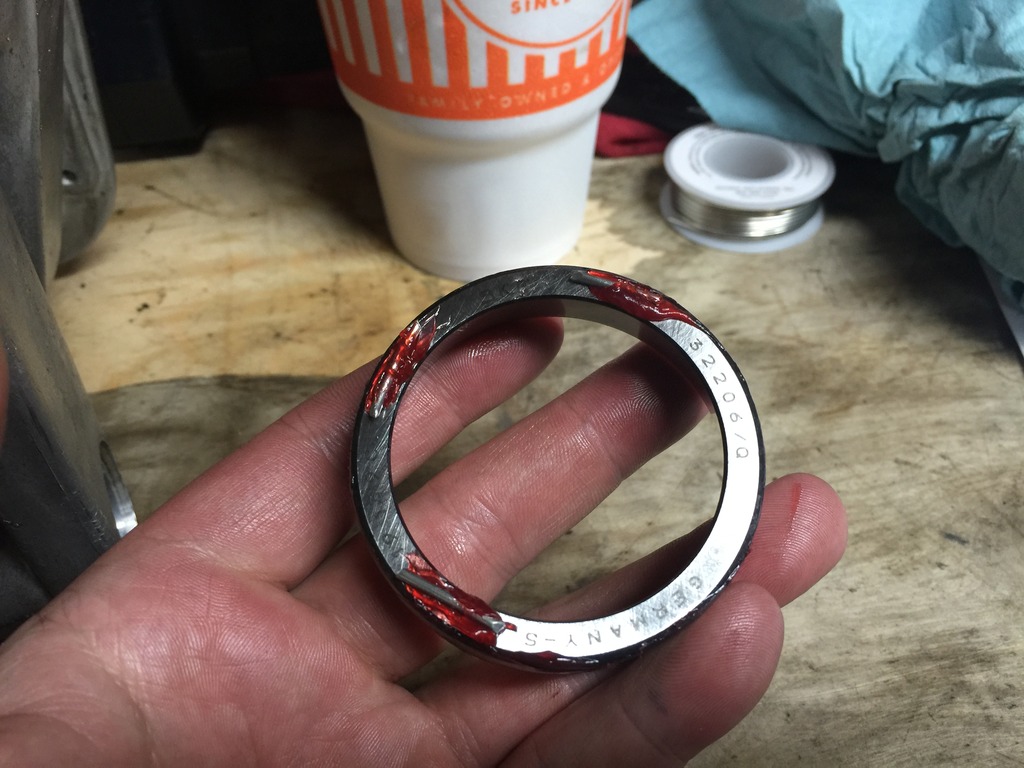
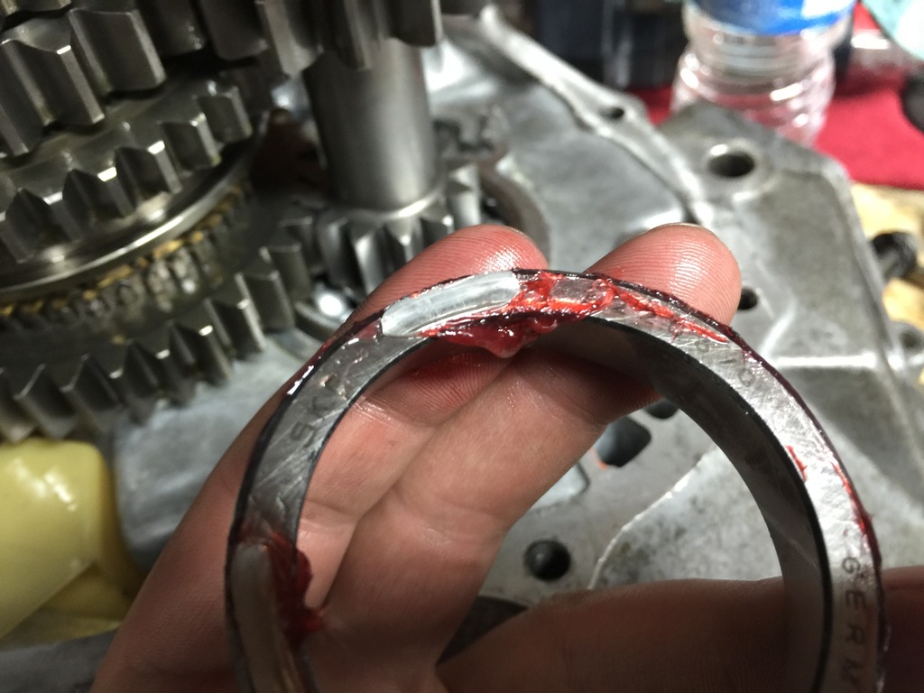
Yes the stock GTiR input shaft is the same as the stock VE (or maybe VG too, to be honest I haven't really looked into the VG in any of this comparison but perhaps the VG is the same as the VE other than the VLSD?). But this PAR unit is much beefier, you can see how it doesn't have that narrow in diameter section on the input shaft like the OEM. Of course I'm not sure how much difference that makes, I mean it's not like people break their actual input shafts. It may just be beefier simply because PAR doesn't care to bother with the extra time/cost of milling the shaft down for no reason.
The SKF is German:

This is the only bearing in my rebuild set that isn't Japanese.
09-25-2015, 06:15 AM
#32

Good stuff James.
Mine has the noisy input shaft bearing (noise is present when foot is off the clutch). I've never dove into transmission work, and dont have the time to start messing with it.
I wish I could send my trans over and just pay you to fix it
Mine has the noisy input shaft bearing (noise is present when foot is off the clutch). I've never dove into transmission work, and dont have the time to start messing with it.
I wish I could send my trans over and just pay you to fix it
 09-26-2015, 08:03 AM
#34
2 VE's are better than one!
Thread Starter
iTrader: (31)
Join Date: Sep 2000
Location: Dallas
Posts: 7,358
Well my (partial) J34290 kit came in. Unfortunately it's missing both the gauging cylinder (J34290-2) AND the actual plunger that I need (J34290-8). So that sucks.
I can still buy J34290-8 new from Kent Moore, but unfortunately the gauging cylinder is discontinued and obsolete. I may be up a creek without a paddle trying to do this the textbook correct way.
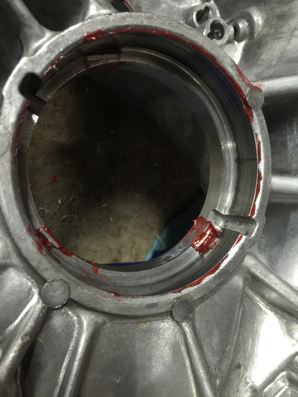
Here is the "bridge" (J34290-1) set up on the bellhousing as described in the FSM:
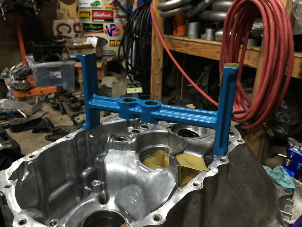
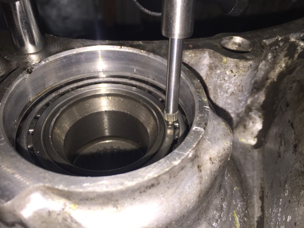
Here is one of the plungers set up according to how (if I'm understanding correctly) the FSM describes it - right on the "ledge" that the race would sit in. This isn't the correct plunger we need (J34290-8), this is just a random one out of the kit for reference:
And you can see how in this position, the bridge and the plunger line right up and the gauging cylinder would be required here:
I am going to keep looking for a while to try to somehow get my hands on these correct missing parts that I need. If not I will reluctantly give up and try a different method - or just not even bother with the shims on the mainshaft as it appears most people do, even "professional" shops. I really want to do this the right way though so I will keep searching a little bit longer.
I can still buy J34290-8 new from Kent Moore, but unfortunately the gauging cylinder is discontinued and obsolete. I may be up a creek without a paddle trying to do this the textbook correct way.
Here is the "bridge" (J34290-1) set up on the bellhousing as described in the FSM:

Here is one of the plungers set up according to how (if I'm understanding correctly) the FSM describes it - right on the "ledge" that the race would sit in. This isn't the correct plunger we need (J34290-8), this is just a random one out of the kit for reference:

And you can see how in this position, the bridge and the plunger line right up and the gauging cylinder would be required here:

I am going to keep looking for a while to try to somehow get my hands on these correct missing parts that I need. If not I will reluctantly give up and try a different method - or just not even bother with the shims on the mainshaft as it appears most people do, even "professional" shops. I really want to do this the right way though so I will keep searching a little bit longer.
09-26-2015, 09:21 AM
#35
So what is the main purpose of the plunger? Is the plunger the height of the mainshaft with bearings? I was also thinking if you tap in the race until it seats (main shaft)...what is the purpose of the shim? It not like the race will move in/out unless you account for thermal expansion and contraction of the alum case....but the bearing race is still not moving. Is the space that small that you need the shim to gap up the race so it seats the rollers better?
09-26-2015, 12:48 PM
#36
2 VE's are better than one!
Thread Starter
iTrader: (31)
Join Date: Sep 2000
Location: Dallas
Posts: 7,358
So what is the main purpose of the plunger? Is the plunger the height of the mainshaft with bearings? I was also thinking if you tap in the race until it seats (main shaft)...what is the purpose of the shim? It not like the race will move in/out unless you account for thermal expansion and contraction of the alum case....but the bearing race is still not moving. Is the space that small that you need the shim to gap up the race so it seats the rollers better?
I notice that comparing the gauging cylinders that I DO have in the kit, most are identical except in height, and we're talking differences in the thousands of an inch, almost imperceptible. So surely each X make/model of transmission is measured with a very specifically designed plunger, with ours requiring 23490-8 of course.
The plungers are short, about about 3 inches long.
Yes the shim merely changes how deep or how shallow the outer race seats. So if you did need a shim based on the C measurement and you drove the outer race all the way in until it seats (with no shim), you'd wind up with too much clearance. Likewise if you did not need a shim and you installed a shim anyway there would be too little clearance. Neither is a good situation of course.
There has to be a way to extrapolate this C measurement out to a different way of measuring it (something like measuring how high above the bellhousing case the gearstack with outer race installed sits above the flat edge of the case mating surface vs measuring how far below the opposite case mating surface the outer race seat rests type of thing, do the math there and arrive at X shim size) but without knowing the dimensions of the plunger and cylinder there seems to be no way to extrapolate it out to a different measurement style given that Nissan only lists their clearances directly based upon the plunger and cylinder measurements.
10-04-2015, 03:01 PM
#38
2 VE's are better than one!
Thread Starter
iTrader: (31)
Join Date: Sep 2000
Location: Dallas
Posts: 7,358
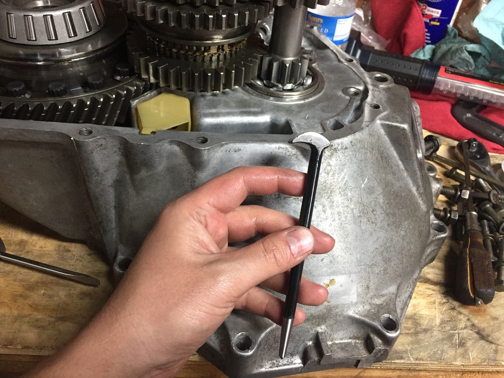
Back working on this some more, I still had to replace the other differential bearing. This one was a real pain. First of all I cut the roller case deal off and of course trashed it and all the rollers, leaving myself just the inner race. I ground in some deeper grooves to fit the bearing splitter better, and clamped my bearing splitter around the top "lip" and used a two jaw puller around it to try to pull it off (as you can see I wrapped the whole thing except the area I needed to work on in a "contractor bag" aka heavy duty trash bag since I had to be cutting on the unit and already had the new bearing on the other side and didn't want a metal shaving mess on my hands). Anyway, this didn't work because it promptly just broke the top "lip" off of the inner race.
Close up of how I was pulling on it:
After that I gave up and started cutting several grooves into it. I've never had as much luck with this style as others seem to have and I ended up breaking the tip off several screwdrivers but eventually it gave way and came off:
New one pressed on:
Now onto the shimming/measuring. I'm going to give up trying to find the proper Kent Moore stuff. You can't even buy the full kit from Kent Moore any longer (not that I could afford it anyway) - all they still sell are a couple of the random plungers themselves, but the actual gauging cylinder you can't buy. I have even checked with dealerships to see if maybe any techs have this part laying around and would let me rent or buy it. So I have decided to try the solder crush method for the mainshaft after consulting with Nealoc187 quite a bit. Neal has been really helpful and as everybody knows a lot of his old posts here are treasure troves of tranny info. I've also gotten some good input from another 4th gen guy, Maximeltman, who has done the solder crush method a couple times on his rebuilds.
Anyway, because the FSM calls for the differential and input shaft to be measured simply via a dial indicator I decided to measure both of those with the dial indicator, and after that do the solder crush method for all three, so I can compare the dial indicator vs solder crush methods (only for the input shaft and differential, obviously).
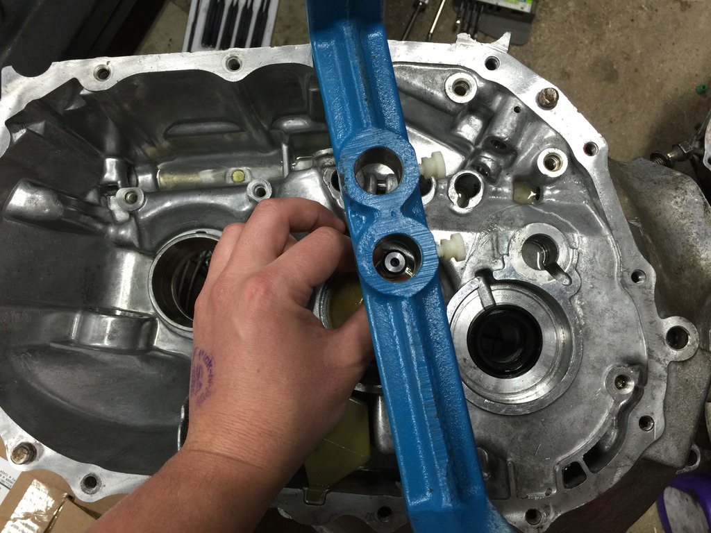
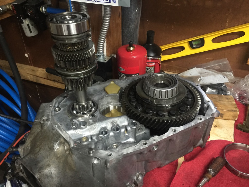
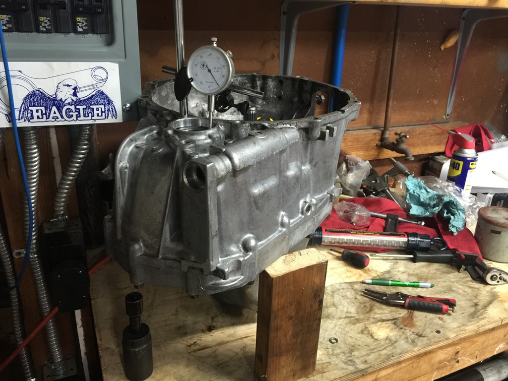
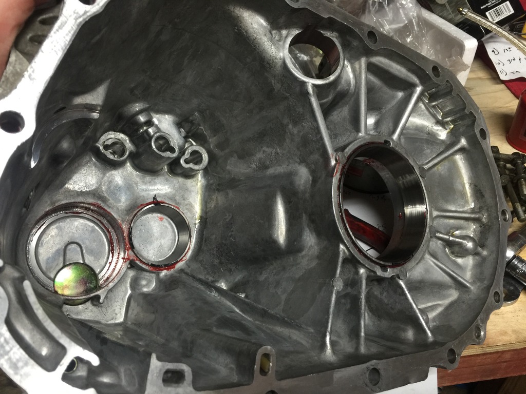
Input shaft and differential installed as per FSM (I read this section about 10 times and it never mentioned installing the mainshaft for this part, so I did just the input shaft and differential. I hope I didn't interpret it incorrectly):
Differential outside race installed with no shims:
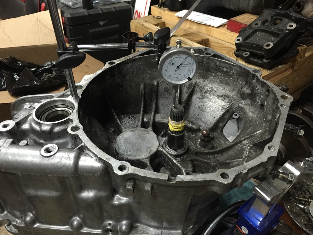
Dial indicator set up on differential. The dial indicator arm setup deal is the HF unit, and thankfully the rod screws right into that bolt hole near the axle opening:
Close up of measuring point:
I used an impact socket and a short extension to push up as hard as I could from the underneath axle opening and measuring the deflection each time. I must have done this 50 times just to be safe. I was amazed how consistent it was, it seemed like it would be .017" five or six times in a row followed by a random .016" or .018" or so. My average ended up being .017". This is very surprising (or even a red flag?) because the average of .017" defection means that this is EXACTLY in spec WITHOUT any shims. The service manual calls for .0157" to .0181", again mine - without shims - is .017" which is near perfect.
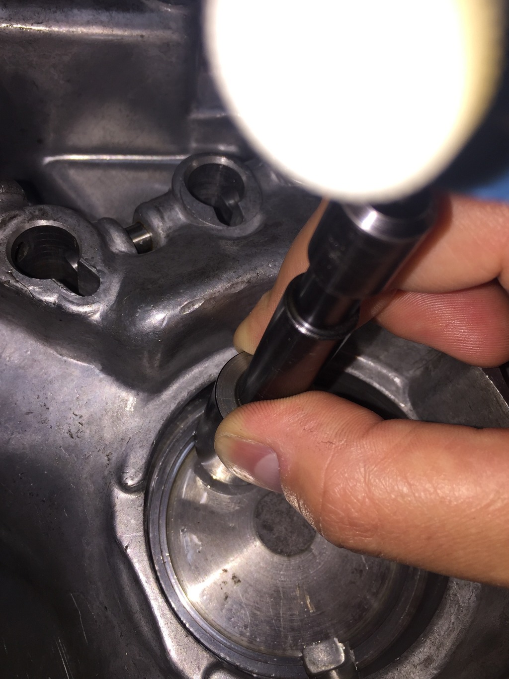
Now onto the input shaft. This one is pretty difficult to do because the FSM calls for you to pull UP on the input shaft and measure deflection. The reason this is difficult is because there's almost no way to grip the input shaft to pull it up - especially since the rear bearing in the outer case is a pretty tight fit and being able to pull the shaft up and move the rear bearing in and out of the outer case with nothing to grip is almost impossible. Honda has an actual tool that clamps around the splines on the shaft and also a vertical bolt that you simple tighten down (which pulls the shaft up) that makes it easy to do this - too bad Nissan doesn't have the same tool. I did grease the rear bearing and before setting the dial indicator in place I made sure to get the input shaft "ready" speak by doing several dry runs and making sure I could feel the rear bearing moving in and out of place as I messed with it. So I set up the dial indicator (using the same bolt hole I mentioned earlier). I also very tightly wrapped the input shaft with rubber bands to try to get some grip.
I did this about 25 times and averaged .040" deflection. This works out to a total shim thickness of .0394" per the FSM.

Close up of how I was pulling on it:

After that I gave up and started cutting several grooves into it. I've never had as much luck with this style as others seem to have and I ended up breaking the tip off several screwdrivers but eventually it gave way and came off:


New one pressed on:

Now onto the shimming/measuring. I'm going to give up trying to find the proper Kent Moore stuff. You can't even buy the full kit from Kent Moore any longer (not that I could afford it anyway) - all they still sell are a couple of the random plungers themselves, but the actual gauging cylinder you can't buy. I have even checked with dealerships to see if maybe any techs have this part laying around and would let me rent or buy it. So I have decided to try the solder crush method for the mainshaft after consulting with Nealoc187 quite a bit. Neal has been really helpful and as everybody knows a lot of his old posts here are treasure troves of tranny info. I've also gotten some good input from another 4th gen guy, Maximeltman, who has done the solder crush method a couple times on his rebuilds.
Anyway, because the FSM calls for the differential and input shaft to be measured simply via a dial indicator I decided to measure both of those with the dial indicator, and after that do the solder crush method for all three, so I can compare the dial indicator vs solder crush methods (only for the input shaft and differential, obviously).
Input shaft and differential installed as per FSM (I read this section about 10 times and it never mentioned installing the mainshaft for this part, so I did just the input shaft and differential. I hope I didn't interpret it incorrectly):

Differential outside race installed with no shims:

Dial indicator set up on differential. The dial indicator arm setup deal is the HF unit, and thankfully the rod screws right into that bolt hole near the axle opening:

Close up of measuring point:

I used an impact socket and a short extension to push up as hard as I could from the underneath axle opening and measuring the deflection each time. I must have done this 50 times just to be safe. I was amazed how consistent it was, it seemed like it would be .017" five or six times in a row followed by a random .016" or .018" or so. My average ended up being .017". This is very surprising (or even a red flag?) because the average of .017" defection means that this is EXACTLY in spec WITHOUT any shims. The service manual calls for .0157" to .0181", again mine - without shims - is .017" which is near perfect.
Now onto the input shaft. This one is pretty difficult to do because the FSM calls for you to pull UP on the input shaft and measure deflection. The reason this is difficult is because there's almost no way to grip the input shaft to pull it up - especially since the rear bearing in the outer case is a pretty tight fit and being able to pull the shaft up and move the rear bearing in and out of the outer case with nothing to grip is almost impossible. Honda has an actual tool that clamps around the splines on the shaft and also a vertical bolt that you simple tighten down (which pulls the shaft up) that makes it easy to do this - too bad Nissan doesn't have the same tool. I did grease the rear bearing and before setting the dial indicator in place I made sure to get the input shaft "ready" speak by doing several dry runs and making sure I could feel the rear bearing moving in and out of place as I messed with it. So I set up the dial indicator (using the same bolt hole I mentioned earlier). I also very tightly wrapped the input shaft with rubber bands to try to get some grip.

I did this about 25 times and averaged .040" deflection. This works out to a total shim thickness of .0394" per the FSM.
10-04-2015, 03:06 PM
#39
2 VE's are better than one!
Thread Starter
iTrader: (31)
Join Date: Sep 2000
Location: Dallas
Posts: 7,358
Today I gave the solder crush method a try, partly because it's about the only method I have to attempt to measure for the mainshaft shim(s), and also out of curiosity to compare the measurements to the FSM dial indicator methods.
This is the solder I went with (.062" diameter):
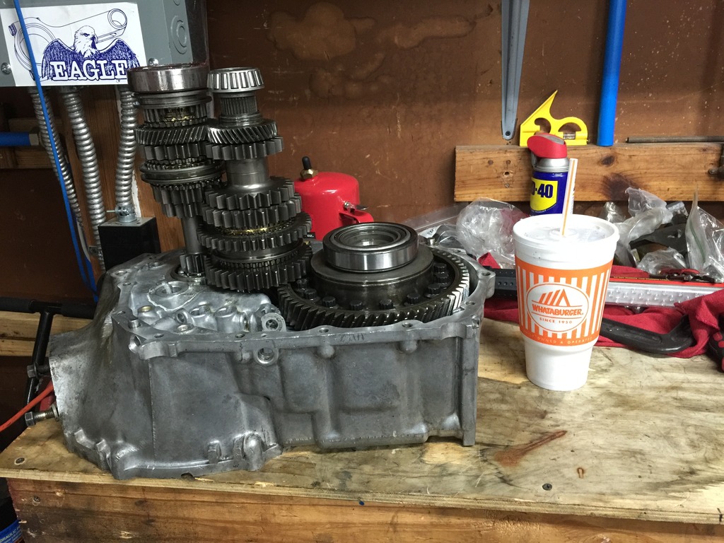
Put both shafts in as well as differential:
Three little sections of the solder placed in the outside transmission case where the differential outer race will go, held in with grease:
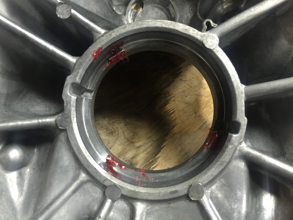
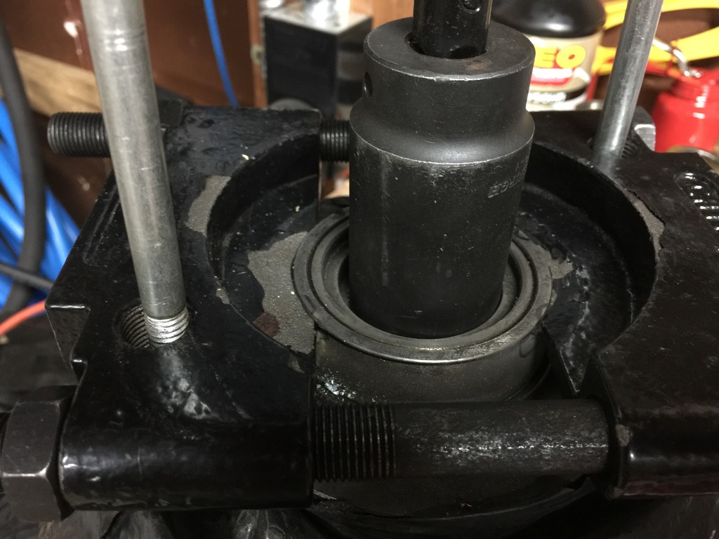
View of differential race hammered in (and I mean hammered, it's very tight, so tight I feel it affected my measurement which I'll explain further down). Notice I stopped just prior to starting to crush the solder:
Solder sections on rear input shaft bearing, again held on with grease:
Solder sections on mainshaft race (making sure to avoid text areas on race):
Mainshaft race tapped in, again making sure not to crush the solder (Sharpie marks to indicate where the stamped text was so I could make sure the solder didn't move out of the spots I wanted):
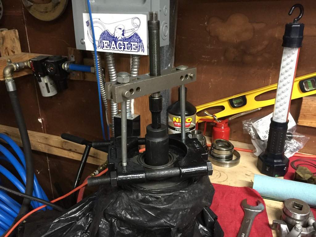
Assembled case, torqued case bolts to spec. Then let it sit this way for an hour:
Pulled case back off, here's the crushed input shaft solder:
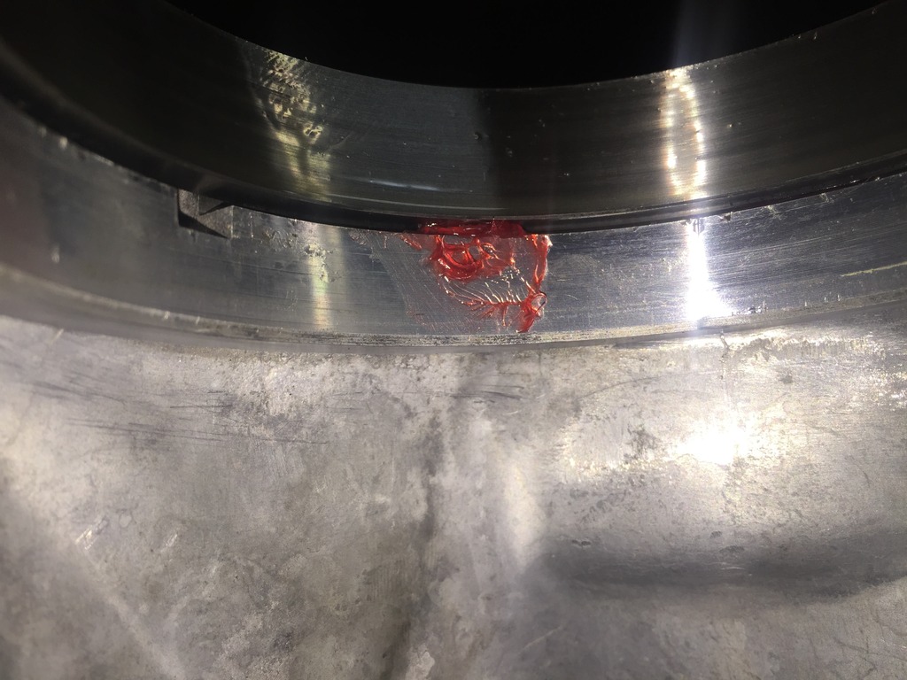
Crushed differential solder:
Crushed mainshaft solder:
And by the way, all this removing races over and over is annoying. The differential race taps out with a flat head screwdriver from the axle seal side. I found the mainshaft bearing to be troublesome to pull out as you can't really get in there. I discovered that the small pry bar from the Harbor Freight 3 pry bar set works PERFECT for the mainshaft race. The entire pry bar set is only like $8. Here it is, works much better/easier/quicker than trying to modify a 3 jaw pilot bushing puller:
Now onto the measurements.
As I mentioned above, my FSM-spec dial indicator methods yielded .017" deflection on the differential and .040" on the input shaft.
Measuring the crushed solder, I got .043" on the input shaft (very close to my .040" measurement per the dial indicator).
As far as the differential, my crushed solder was .040, which is SUBSTANTIALLY different from my dial indicator .017". Like I stated above the differential race was very difficult (tight) going into the transmission case. So tight I actually had to hammer it in with a lot of force. I really think the tightness of the race meant that the solder couldn't crush down like it should (because if I have to HAMMER the race in, how in the world could the simple pressure of the case being assembled press the race in?). So that's disappointing.
If my FSM-spec measurement hadn't yielded a number that inexplicably calls for no shim(s), I would be a lot more confident here.
Just for ****s and giggles I re-did the differential measurement again with the dial indicator and again came up with the same measurement. I guess I will go with no shim. I suppose it's entirely possible to just happen to have the perfect preload but it just seems so unlikely statistically.
As far as the mainshaft crushed solder, that ended up being .017", which calls for a total shim range of .0268" to .0292".
So to sum it all up, my necessary shim thicknesses are:
Differential = no shim necessary
Input shaft = ~ .0394" shim thickness
Mainshaft = ~ .0283" shim thickness
This is the solder I went with (.062" diameter):

Put both shafts in as well as differential:

Three little sections of the solder placed in the outside transmission case where the differential outer race will go, held in with grease:

View of differential race hammered in (and I mean hammered, it's very tight, so tight I feel it affected my measurement which I'll explain further down). Notice I stopped just prior to starting to crush the solder:

Solder sections on rear input shaft bearing, again held on with grease:

Solder sections on mainshaft race (making sure to avoid text areas on race):

Mainshaft race tapped in, again making sure not to crush the solder (Sharpie marks to indicate where the stamped text was so I could make sure the solder didn't move out of the spots I wanted):

Assembled case, torqued case bolts to spec. Then let it sit this way for an hour:

Pulled case back off, here's the crushed input shaft solder:

Crushed differential solder:

Crushed mainshaft solder:

And by the way, all this removing races over and over is annoying. The differential race taps out with a flat head screwdriver from the axle seal side. I found the mainshaft bearing to be troublesome to pull out as you can't really get in there. I discovered that the small pry bar from the Harbor Freight 3 pry bar set works PERFECT for the mainshaft race. The entire pry bar set is only like $8. Here it is, works much better/easier/quicker than trying to modify a 3 jaw pilot bushing puller:

Now onto the measurements.
As I mentioned above, my FSM-spec dial indicator methods yielded .017" deflection on the differential and .040" on the input shaft.
Measuring the crushed solder, I got .043" on the input shaft (very close to my .040" measurement per the dial indicator).
As far as the differential, my crushed solder was .040, which is SUBSTANTIALLY different from my dial indicator .017". Like I stated above the differential race was very difficult (tight) going into the transmission case. So tight I actually had to hammer it in with a lot of force. I really think the tightness of the race meant that the solder couldn't crush down like it should (because if I have to HAMMER the race in, how in the world could the simple pressure of the case being assembled press the race in?). So that's disappointing.
If my FSM-spec measurement hadn't yielded a number that inexplicably calls for no shim(s), I would be a lot more confident here.
Just for ****s and giggles I re-did the differential measurement again with the dial indicator and again came up with the same measurement. I guess I will go with no shim. I suppose it's entirely possible to just happen to have the perfect preload but it just seems so unlikely statistically.
As far as the mainshaft crushed solder, that ended up being .017", which calls for a total shim range of .0268" to .0292".
So to sum it all up, my necessary shim thicknesses are:
Differential = no shim necessary
Input shaft = ~ .0394" shim thickness
Mainshaft = ~ .0283" shim thickness
10-04-2015, 08:47 PM
#40
2 VE's are better than one!
Thread Starter
iTrader: (31)
Join Date: Sep 2000
Location: Dallas
Posts: 7,358
I just had an epiphany about this apparent no shim on the differential. I just realized I have been thinking about this incorrectly. My deflection measurement of .017" doesn't mean that it requires no shim, it just merely means my deflection measurement is "off the charts". It just happened to confuse me for some reason earlier I guess because the .017" deflection just happened to be in the exact middle of the desired preload range (i.e., if the deflection had been, say .030" I probably wouldn't have erroneously made that same mistake/assumption).
Anyway, the lowest deflection range listed in the manual is .0185" to .0201", which requires a total shim of .0362". I sat down and extrapolated out the deflection and shim chart down to where I need it. I noticed each deflection range spans .0016" (some are technically .0015"), and each total shim thickness for the respective ranges also span 0.0016" between each "step". So, if my extrapolation/math is correct, the next deflection range (if you picture it at the top of the Nissan chart on page MT 40) would be .0169" to .0185" - this is the range I need.
This means that my necessary differential shim should be .0346" for a differential deflection of .017" - assuming I am finally thinking clearly here. Whew.
Having said that, that is still quite a bit smaller shim than the .0557" to .0581" shim the solder crush method would call for on the differential - but again, the race is so tight it requires hammering to go in and wouldn't press in on its own with the solder crush.