So...who wants a gear indicator in the cluster?

 10-15-2009, 01:46 PM
#122
Senior Member

Join Date: Mar 2009
Location: Philadelphia, PA
Posts: 472
You don't have to cut out the whole area of PRND21, you can just notch out the area where the contacts of the buld holder may have contact with. That's why when I do mine I'm going to use the Bulb holders with regular bulbs (forgot the size I know those are smaller than 194 I believe) rather than solder leds in place. Then mod the power feed in the buld holders. I think its easier that way.
10-15-2009, 01:52 PM
#123
 10-15-2009, 01:59 PM
#124
 10-17-2009, 07:31 AM
#125

ok.
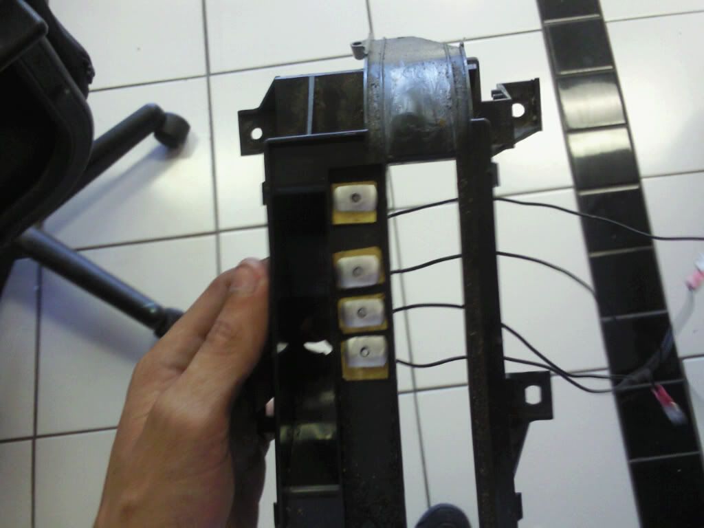
what do you guys think of this?
yeah, i know it needs cleaning. this is the first time i opened it..
and by the way..... won't it be hard for the other guys to take this piece out? since the factory shifter is basically wired in? i had to cut mine apart and rewire my O/D because i have a stainless steel shifter.. o_O

yeah, i know it needs cleaning. this is the first time i opened it..
and by the way..... won't it be hard for the other guys to take this piece out? since the factory shifter is basically wired in? i had to cut mine apart and rewire my O/D because i have a stainless steel shifter.. o_O
Last edited by dkillahster; 10-17-2009 at 07:34 AM.
10-17-2009, 08:02 AM
#126
what do you guys think of this?
yeah, i know it needs cleaning. this is the first time i opened it..
and by the way..... won't it be hard for the other guys to take this piece out? since the factory shifter is basically wired in? i had to cut mine apart and rewire my O/D because i have a stainless steel shifter.. o_O
yeah, i know it needs cleaning. this is the first time i opened it..
and by the way..... won't it be hard for the other guys to take this piece out? since the factory shifter is basically wired in? i had to cut mine apart and rewire my O/D because i have a stainless steel shifter.. o_O
Last edited by maxprivate; 10-17-2009 at 08:26 AM.
10-17-2009, 08:16 AM
#127
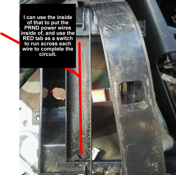
well, the red tab has like a gap this big between that piece --> [ ] so maybe i can fab up something and see. still working on it.
10-17-2009, 08:37 AM
#128
Since I think the easiest way is to use the shifter as the ground side of the circuit, you can maybe pop rivet a piece of wire and make sure you get a good ground on the orange tap. Then stick each wire for PRND21 in there correct location. Then run your wires over to the cluster and with a volt meter check continuity to ground for each wire while in that gear ie, P continuity to ground, R continuity to ground etc. Once you get continuity to ground on each of the wires while in that gear you know you will have a complete circuit while in the gear hence lighting each bulb. At that point all you would have to do is grab power from maybe the dimmer switch, feed one side of each bulb or LED (which ever you choose) and your done. Make sense?
Last edited by maxprivate; 10-17-2009 at 08:50 AM.
10-18-2009, 06:37 PM
#129
Newbie - Just Registered

Join Date: Oct 2009
Location: providence, RI
Posts: 10
GREAT IDEA
i currently am doing the auto shifter **** from stock to a cooler looking one with a shift boot, so it appears to be manual a little. the gauge prndl display write up should be a great help instead of trying to guess what u shifted to.
10-19-2009, 07:50 PM
#130

Ya'll are barking up the way wrong tree here.
If ya'll want a switch assembly, look in the Gen 5.5 FSM, AT section and find the "PNP switch", it contains the "transmission range switch"
Also check the EL section of the 5.5 FSM, it shows the schematic for the PNP switch. The PNP switch can be attached to the Gen 4 auto trans, use a wire harness clipping from a wrecked Gen 5 and wire it up that way.
10-19-2009, 08:02 PM
#131
Ya'll are barking up the way wrong tree here.
If ya'll want a switch assembly, look in the Gen 5.5 FSM, AT section and find the "PNP switch", it contains the "transmission range switch"
Also check the EL section of the 5.5 FSM, it shows the schematic for the PNP switch. The PNP switch can be attached to the Gen 4 auto trans, use a wire harness clipping from a wrecked Gen 5 and wire it up that way.
If ya'll want a switch assembly, look in the Gen 5.5 FSM, AT section and find the "PNP switch", it contains the "transmission range switch"
Also check the EL section of the 5.5 FSM, it shows the schematic for the PNP switch. The PNP switch can be attached to the Gen 4 auto trans, use a wire harness clipping from a wrecked Gen 5 and wire it up that way.
10-19-2009, 08:09 PM
#132
Look at the Gen 4 and 5.5 FSM's and you'll see how to attach the PNP in place of the inhibitor switch.
BTW, for anyone interested I updated post #90, you can see a Gen 4 with PRND321 indicator.
10-19-2009, 08:20 PM
#133
When I had the Gen 4 AT out next to the Gen 5.5 AT, the "inhibitor" switch on the Gen 4 AT and the "PNP" switch on the Gen 5.5 AT appeared interchangeable, as they must be since JDM and KDM A32's have the PRNDL indicator with this model trans.
Look at the Gen 4 and 5.5 FSM's and you'll see how to attach the PNP in place of the inhibitor switch.
BTW, for anyone interested I updated post #90, you can see a Gen 4 with PRND321 indicator.
Look at the Gen 4 and 5.5 FSM's and you'll see how to attach the PNP in place of the inhibitor switch.
BTW, for anyone interested I updated post #90, you can see a Gen 4 with PRND321 indicator.
So your basically saying I can use the Inhibitor swith on the 4th gen and swap it out for a PNP switch from a 5.5 gen and i can add the PRND21 display in the cluster in the 4th gen cluster say from the New Zealand Cefiro and the display will work?
10-19-2009, 08:42 PM
#134
I saw the updated post, what cluster is that from? that in a 4th gen?
So your basically saying I can use the Inhibitor swith on the 4th gen and swap it out for a PNP switch from a 5.5 gen and i can add the PRND21 display in the cluster in the 4th gen cluster say from the New Zealand Cefiro and the display will work?
So your basically saying I can use the Inhibitor swith on the 4th gen and swap it out for a PNP switch from a 5.5 gen and i can add the PRND21 display in the cluster in the 4th gen cluster say from the New Zealand Cefiro and the display will work?
Basically, yes. I would suggest that you acquire a used PNP switch and harness clipping from a Gen 5.5 (Gen 5 maybe OK?) for a fair price and try to install it on your Maxima. From what I saw, and what is in the FSM these parts are physically interchangeable, you would just need to wire in the new sub-harness. BTW, the Gen 5.5 PNP switch has two parts, one part is just like the Gen 4 inhibitor, and the other part has the switches for the PRND321 display. Please refer to the FSM EL section, "A/T INDICATOR" of the Gen 4 and 5.5 to see what I mean.
 10-20-2009, 04:53 AM
#136
The cluster is from a 2004 I35
Basically, yes. I would suggest that you acquire a used PNP switch and harness clipping from a Gen 5.5 (Gen 5 maybe OK?) for a fair price and try to install it on your Maxima. From what I saw, and what is in the FSM these parts are physically interchangeable, you would just need to wire in the new sub-harness. BTW, the Gen 5.5 PNP switch has two parts, one part is just like the Gen 4 inhibitor, and the other part has the switches for the PRND321 display. Please refer to the FSM EL section, "A/T INDICATOR" of the Gen 4 and 5.5 to see what I mean.
Basically, yes. I would suggest that you acquire a used PNP switch and harness clipping from a Gen 5.5 (Gen 5 maybe OK?) for a fair price and try to install it on your Maxima. From what I saw, and what is in the FSM these parts are physically interchangeable, you would just need to wire in the new sub-harness. BTW, the Gen 5.5 PNP switch has two parts, one part is just like the Gen 4 inhibitor, and the other part has the switches for the PRND321 display. Please refer to the FSM EL section, "A/T INDICATOR" of the Gen 4 and 5.5 to see what I mean.
Looking at the diagram on the FSM manuels it looks like there's wiring involved to get the PNP swith from the 5th gen to work with the inhibitor switch for the 4th Gen. So still don't see how this would send power to those empty PRND21 bulb slots on the back of the 4th gen cluster though. Also I can't tell where the inhibitor switch is located on the 4th gen. Does the car need to be on a lift to access the switch?
 10-20-2009, 05:50 PM
#138
Are you reading into what Made In China is saying about being able to use
the Inhibitor switch and intergrate with the 5 gen PNP switch to make the display work? Also what will you do for a display in the gauge cluster?
10-21-2009, 05:57 AM
#139
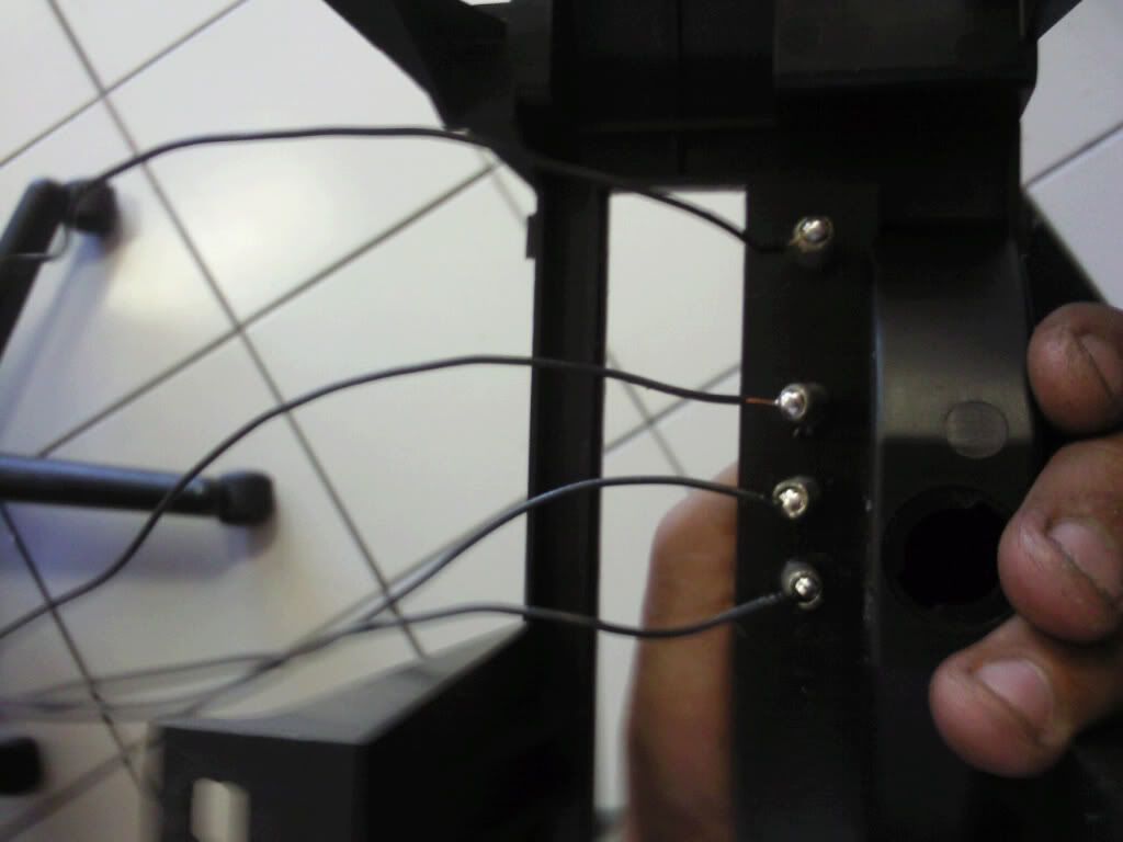
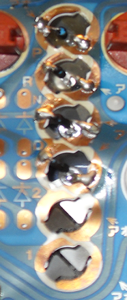
Looks like your idea will work. Are you using pop rivets there with some type of washer on top side? you should use that side there for the ground side of the circuit and for power use the dimmer switch for power. How are you making the orange indicator make contact with each of those circuits?
Are you reading into what Made In China is saying about being able to use
the Inhibitor switch and intergrate with the 5 gen PNP switch to make the display work? Also what will you do for a display in the gauge cluster?
Are you reading into what Made In China is saying about being able to use
the Inhibitor switch and intergrate with the 5 gen PNP switch to make the display work? Also what will you do for a display in the gauge cluster?
I feel better about myself making something for my maxima rather as buying something and hooking it up. But i mean, to each his own.
 10-21-2009, 06:39 AM
#140
yes those are rivets. the PRND display clear piece that is near the shifter, ima take that and use that inside the guage cluster. and ima just take a e-brake broke to cover the shifter. other than that, i got a way to make the orange tab touch the rivets and complete the ground circuit. i'm still in the process of it. i just need to get on it. because i'm still in school and i am trying to get my grades as well. sorry for the delay. And yes i did see what Made In China was saying, but i didn't want to go through all that.
I feel better about myself making something for my maxima rather as buying something and hooking it up. But i mean, to each his own.
I feel better about myself making something for my maxima rather as buying something and hooking it up. But i mean, to each his own.
I don't see how the heck you will get that big **** display in the cluster
 im trying to get a hold of the display that fits right in place like the one ptatoehed has, then I'll start mine. As for the shift boot check out Redline.com Maciek the owner there can hook you up with a real leather custom one. I got my ebrake boot, arm rest cover and shift boot custom made from them quality is excellent you will not be disappointed.
 Getting back to the inhibitor switch....It would be nice to get it to work but it would involve some rewiring. I also may just make up my own circiut like you are since no one has confirmed it would work or posted a how to on it. I'll see which is easier when I start mine. If you get yours to work you will be the first to have confirmed getting the stock cluster to have a working shift display. I wonder how Ptatoeheds worked out.
10-21-2009, 01:14 PM
#141
I hear ya I'm also in school full time and work full time.
I don't see how the heck you will get that big **** display in the cluster face im trying to get a hold of the display that fits right in place like the one ptatoehed has, then I'll start mine. As for the shift boot check out Redline.com Maciek the owner there can hook you up with a real leather custom one. I got my ebrake boot, arm rest cover and shift boot custom made from them quality is excellent you will not be disappointed.
Getting back to the inhibitor switch....It would be nice to get it to work but it would involve some rewiring. I also may just make up my own circiut like you are since no one has confirmed it would work or posted a how to on it. I'll see which is easier when I start mine. If you get yours to work you will be the first to have confirmed getting the stock cluster to have a working shift display. I wonder how Ptatoeheds worked out.
I don't see how the heck you will get that big **** display in the cluster face
im trying to get a hold of the display that fits right in place like the one ptatoehed has, then I'll start mine. As for the shift boot check out Redline.com Maciek the owner there can hook you up with a real leather custom one. I got my ebrake boot, arm rest cover and shift boot custom made from them quality is excellent you will not be disappointed. Getting back to the inhibitor switch....It would be nice to get it to work but it would involve some rewiring. I also may just make up my own circiut like you are since no one has confirmed it would work or posted a how to on it. I'll see which is easier when I start mine. If you get yours to work you will be the first to have confirmed getting the stock cluster to have a working shift display. I wonder how Ptatoeheds worked out.
and another thing was.. Since i finally realized that i sold the LED wedge bulbs, (197/194) ?? I decided to get 2 wedge LEDs' out and test them out on the MPH part of the cluster, And since they are White, I noticed a HUGE difference. The guage cluster looks way better than the one bought on ebay for about 20 bucks.. so ima stick with that, and install the rest of the LED's in. but other than that, the positive wires are going to ran from the dimmer switch and the ground will be tapped into the body of the car besides the shifter. and ima solder the ground to the chasis as well, to ensure a good connection. but we will see how this will work out.
and it may not please you other .orgers out there but ima stick with white background behind the PRND Display. 2 and 1 are gonna be Obselete since i don't need to light those up.
but we shall see
Last edited by dkillahster; 10-21-2009 at 01:16 PM.
10-21-2009, 02:22 PM
#143
10-21-2009, 02:40 PM
#144
ok..
i'll honestly say, i was never taught how to read a ruler except the inches.. so i post pictures up.. maybe that will help?
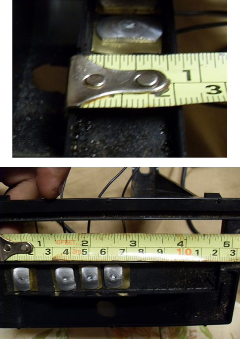
sorry. i really and truely can't take a guess of exact mesurements.. =(
i feel stupid actually lol
sorry. i really and truely can't take a guess of exact mesurements.. =(
i feel stupid actually lol
10-21-2009, 03:00 PM
#145
don't forget that there is plenty of room under that piece pictured. I'm going to mount a terminal board under it and have some type of linkage between the shifter and the terminal board that will move in unison completing a circiut to each bulb as I shift .Nice to see different ideas though.
10-21-2009, 05:06 PM
#146
Senior Member
Thread Starter
iTrader: (11)

Join Date: Aug 2006
Location: Sunshine State
Posts: 4,717
don't forget that there is plenty of room under that piece pictured. I'm going to mount a terminal board under it and have some type of linkage between the shifter and the terminal board that will move in unison completing a circiut to each bulb as I shift .Nice to see different ideas though.
10-21-2009, 07:52 PM
#147
I gotta say for someone who can't read a ruler, you are a very ingenious guy. I almost like your setup better than the stock PNP setup, it could be a viable alternative to the way I was suggesting.
10-21-2009, 08:14 PM
#148
well I'm not sure exactly what the PNP route fully involves but the way it is planned here should work out fine.
 10-24-2009, 04:24 PM
#150
ok
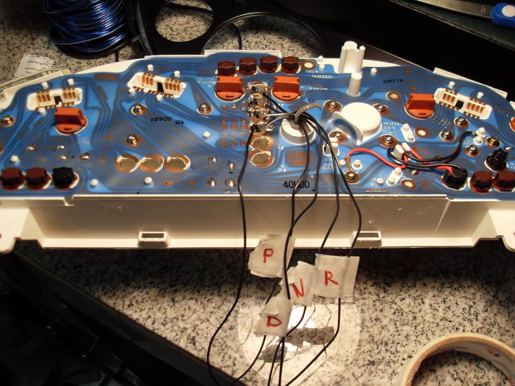
I had went ahead and soldered in my white LED's i bought from advanced auto parts for about 10 bucks.. they only had 4.. so i guess 4 is enough.. because i am only doing the PRND and thats it. here is a picture of them soldered in to the back.
I forget what to do after this.. o_O
can i just have live power feeding all the LED's and then just using the switch to ground and complete the circuit? i forget, i'm just worried they all might turn on when i do that. o_O
but i think thats how it should be done?
I forget what to do after this.. o_O
can i just have live power feeding all the LED's and then just using the switch to ground and complete the circuit? i forget, i'm just worried they all might turn on when i do that. o_O
but i think thats how it should be done?
 10-24-2009, 05:19 PM
#153
I had went ahead and soldered in my white LED's i bought from advanced auto parts for about 10 bucks.. they only had 4.. so i guess 4 is enough.. because i am only doing the PRND and thats it. here is a picture of them soldered in to the back.
I forget what to do after this.. o_O
can i just have live power feeding all the LED's and then just using the switch to ground and complete the circuit? i forget, i'm just worried they all might turn on when i do that. o_O
but i think thats how it should be done?
I forget what to do after this.. o_O
can i just have live power feeding all the LED's and then just using the switch to ground and complete the circuit? i forget, i'm just worried they all might turn on when i do that. o_O
but i think thats how it should be done?
 10-25-2009, 01:42 AM
#155
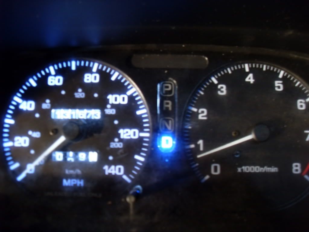
 it seems you are the first to have acccomplished this. How did you get the orange indicator in the shifter diplay to make contact with your rivets? Can you take a pic of the way the connection is?

 10-25-2009, 01:05 PM
#158
well, of course the tab was used to go over the rivets. so what i did was took a thin piece of metal and cut it to fit inside the inner piece of the tab. (under it) and then took my solder iron, and melted the plastic around the metal piece to make it stay put. then i took a wire and soldered it onto the metal piece in the tab and hooked power wire to it. i should have taken pictures of how i did it. but everything is tied down and i'm too lazy to pull it apart scared that it will come aloose.. so yeah
i aint very wordy on my stuff but yeah
