So...who wants a gear indicator in the cluster?
 10-27-2007, 06:25 PM
#1
Senior Member
Thread Starter
iTrader: (11)

Join Date: Aug 2006
Location: Sunshine State
Posts: 4,717
So...who wants a gear indicator in the cluster?
Anyone? I am working on a way to get the PRND21 indicator into the gauge cluster. It wont be super hard, just a lot of wiring and time to get it right. And a bit risky cutting up the gauge bezel. But we'll see how it works out.

 10-27-2007, 06:27 PM
#2

i wanted to do that but i did a 5 speed swap so now it would be usless.. unless i can figure out how to make it display what gear its in.. lol
i wonder why they had the display there but not using it... does any other nissan use the same cluster and have those working
i wonder why they had the display there but not using it... does any other nissan use the same cluster and have those working

 10-27-2007, 06:51 PM
#5
 10-27-2007, 07:30 PM
#8
Senior Member
Thread Starter
iTrader: (11)
Join Date: Aug 2006
Location: Sunshine State
Posts: 4,717
Parts arent really the issue. All that is needed is some bulbs like the existing indicators in the cluster, a whole bunch of wiring, some other stuff and a lot of time.
That is my cluster, BTW.
Speaking of which, would anyone like to donate some spare bulbs and sockets? I just need 6, the small(not 194) type that are like for the CEL, Brake, Washer Fluid lights. If anybody has a lot of spares they would like to donate, or sell for a decent price, let me know!
That is my cluster, BTW.
Speaking of which, would anyone like to donate some spare bulbs and sockets? I just need 6, the small(not 194) type that are like for the CEL, Brake, Washer Fluid lights. If anybody has a lot of spares they would like to donate, or sell for a decent price, let me know!
Last edited by MOHFpro90; 10-27-2007 at 07:36 PM.
 10-28-2007, 10:39 AM
#10

i wanted to do that but i did a 5 speed swap so now it would be usless.. unless i can figure out how to make it display what gear its in.. lol
i wonder why they had the display there but not using it... does any other nissan use the same cluster and have those working
i wonder why they had the display there but not using it... does any other nissan use the same cluster and have those working
displaying what gear on a manual your in would be AWESONME.. i would spend the moeny for that.. on one of those little number leds in teh cluster would be soo useful .. just for those rare occasions where your jsut a bit confused...
10-28-2007, 11:27 AM
#11
Senior Member
Thread Starter
iTrader: (11)
Join Date: Aug 2006
Location: Sunshine State
Posts: 4,717
That would not be too hard either. Although, it would require much more work than an auto.
I will probably work on this tomorrow, Ill be at the hospital a bit today, but I should be free tomorrow some.
I will probably work on this tomorrow, Ill be at the hospital a bit today, but I should be free tomorrow some.
10-28-2007, 02:49 PM
#12

wonder where the output signal comes from in the cefiros if they actually had this. then it would just be a matter of running wires.
also wonder what you would need to add wires to the associated plug for the cluster
also wonder what you would need to add wires to the associated plug for the cluster
10-28-2007, 07:19 PM
#13

Inb4Ptatohed...
I hope you follow through with this, as Ptatohed and many others will be pretty stoked if you pull this off.
Ptatohed has been trying to get an OEM gauge cluster forever from a couple of guys in New Zealand, but they keep flaking on him. Then we were going to tackle this project too.
Do it!
I hope you follow through with this, as Ptatohed and many others will be pretty stoked if you pull this off.
Ptatohed has been trying to get an OEM gauge cluster forever from a couple of guys in New Zealand, but they keep flaking on him. Then we were going to tackle this project too.
Do it!
10-28-2007, 08:06 PM
#14

just another idea.....you can always custom make a read-out that displays "MAXIMA" in the spaces for the PRDN21 (PRDN21 is six characters long, and so is MAXIMA...coindence?  ). It would simply be a cosmetic mod, nothing more, but might be of interest to some. Basically wire up the bulbs for each of the six holes and put a clear peice of plastic in each hole, with one letter from the word 'maxima' inscribed/painted/written/whatever in each appropriate hole. You'd end up with something like:
(M)
(A)
(X)
(I)
(M)
(A)
again, just a thought. and no, i haven't done the mod, nor do I plan to
). It would simply be a cosmetic mod, nothing more, but might be of interest to some. Basically wire up the bulbs for each of the six holes and put a clear peice of plastic in each hole, with one letter from the word 'maxima' inscribed/painted/written/whatever in each appropriate hole. You'd end up with something like:(M)
(A)
(X)
(I)
(M)
(A)
again, just a thought. and no, i haven't done the mod, nor do I plan to
10-28-2007, 08:15 PM
#15
just another idea.....you can always custom make a read-out that displays "MAXIMA" in the spaces for the PRDN21 (PRDN21 is six characters long, and so is MAXIMA...coindence? ). It would simply be a cosmetic mod, nothing more, but might be of interest to some. Basically wire up the bulbs for each of the six holes and put a clear peice of plastic in each hole, with one letter from the word 'maxima' inscribed/painted/written/whatever in each appropriate hole. You'd end up with something like:
(M)
(A)
(X)
(I)
(M)
(A)
again, just a thought. and no, i haven't done the mod, nor do I plan to
). It would simply be a cosmetic mod, nothing more, but might be of interest to some. Basically wire up the bulbs for each of the six holes and put a clear peice of plastic in each hole, with one letter from the word 'maxima' inscribed/painted/written/whatever in each appropriate hole. You'd end up with something like:(M)
(A)
(X)
(I)
(M)
(A)
again, just a thought. and no, i haven't done the mod, nor do I plan to
(N)
(I)
(S)
(S)
(A)
(N)
=--------------------------------
(B)
(A)
(N)
(A)
(N)
(A)
So many possibilities
 10-28-2007, 08:46 PM
#19
so it looks easy.... find the wires at the inhibitor switch.. and measure how much output voltage comes out of them...
this is just a preliminary thought ....what i would do (but cant since i did a 5 speed swap) is to run all 6 wires from the inhibitor to a board with 6 transistors.. ( since the voltage is probably gonna be like 5 volts at the inhibitor) bias the transistors and then put in the bulbs on the cluster and u should be in good shape...
this is just a preliminary thought ....what i would do (but cant since i did a 5 speed swap) is to run all 6 wires from the inhibitor to a board with 6 transistors.. ( since the voltage is probably gonna be like 5 volts at the inhibitor) bias the transistors and then put in the bulbs on the cluster and u should be in good shape...
10-28-2007, 09:08 PM
#20
10-28-2007, 09:16 PM
#21

The face in my '97 cluster did not have it.
And the A32 doesn't have the wiring for the gear indicator. But you should be able to steal the signals from the TCM connector.
When I was in Korea, my friend had a 2002 Samsung Maxima (A32), and it had the exact same cluster as our cars except it had the AT position indicator and another one for VDC and hands free phone.
10-28-2007, 10:14 PM
#23
10-28-2007, 10:20 PM
#24
Senior Member
Thread Starter
iTrader: (11)
Join Date: Aug 2006
Location: Sunshine State
Posts: 4,717
Maranello, I dont think it would even be that hard. Actually, I think for autos it will be amazingly simple. Ill have to test it tomorrow though.
If my idea doesnt work, I will probably use the stock shifter as a variable switch, each position having its own set of (+) input and ouput. Ill have to see how feasible that is too.
If my idea doesnt work, I will probably use the stock shifter as a variable switch, each position having its own set of (+) input and ouput. Ill have to see how feasible that is too.
10-28-2007, 10:29 PM
#25
You can't use the PN switch to determine selector lever position, it only shows when you're in...park or neutral. Grounds out the switch, otherwise it's just open.
You'd have to find another way of doing it, either electrically from the TCM or phyically determining the position of the shifter.
10-28-2007, 11:01 PM
#26

Inb4Ptatohed...
I hope you follow through with this, as Ptatohed and many others will be pretty stoked if you pull this off.
Ptatohed has been trying to get an OEM gauge cluster forever from a couple of guys in New Zealand, but they keep flaking on him. Then we were going to tackle this project too.
Do it!
I hope you follow through with this, as Ptatohed and many others will be pretty stoked if you pull this off.
Ptatohed has been trying to get an OEM gauge cluster forever from a couple of guys in New Zealand, but they keep flaking on him. Then we were going to tackle this project too.
Do it!
10-29-2007, 12:06 AM
#27

Good thing I have a spare guage cluster (USA, not Japanese). I took it apart and noticed some issues that could be a problem for this mod. It would require a bit more than just some wirings.
.jpg)
Back of cluster showing PRND21
.jpg)
Noticed the middle part verses the top part that shows your signals or highbeam
.jpg)
Close up. It's a solid black piece. It won't allow light to shine through
.jpg)
Reverse side of it
.jpg)
Noticed my finger on the other side
No where in the guage will light up the gear you are in.

Back of cluster showing PRND21

Noticed the middle part verses the top part that shows your signals or highbeam

Close up. It's a solid black piece. It won't allow light to shine through

Reverse side of it

Noticed my finger on the other side
No where in the guage will light up the gear you are in.
Last edited by aznprid972; 10-29-2007 at 12:09 AM.
10-29-2007, 12:12 AM
#28
Well that's already known, we'd have to dremel out the face, or get a face from a different country. Beyond that, it's some wiring and some bulbs, basically.
10-29-2007, 08:42 AM
#29
nycmaximas member

Join Date: May 2003
Location: Brooklyn, NY
Posts: 644

 10-29-2007, 09:32 AM
#30
as long as ur puttin REDSOX might as well think of some other things that represent boston.
(C)
(H)
(E)
(A)
(T)
(S)
(R)
(A)
(C)
(I)
(S)
(T)
(D)
(R)
(U)
(N)
(K)
(S)
theres more but my boss is coming around
(C)
(H)
(E)
(A)
(T)
(S)
(R)
(A)
(C)
(I)
(S)
(T)
(D)
(R)
(U)
(N)
(K)
(S)
theres more but my boss is coming around
10-29-2007, 10:20 AM
#32
so if this mod was done using a modified usdm cluster would it just be a light (no letters)?
i think it would look cool to drill out individual holes rather than cut out the whole area, but without letters it might be kind of pointless.
i think it would look cool to drill out individual holes rather than cut out the whole area, but without letters it might be kind of pointless.
10-30-2007, 05:43 PM
#35
Senior Member
Thread Starter
iTrader: (11)
Join Date: Aug 2006
Location: Sunshine State
Posts: 4,717
Well, I looked at what weve got.
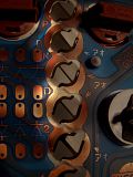
The traces on the back of the cluster are FOR the indicator. If you looked just to the left of the column of sockets, there are 12 pads. There are markings for a resistor to go across for supporting LEDs. Follow their source, and they lead to a plug. The plug, however, has no wires. (see picture below)
.jpg)
So, what would need to be done is the following:
1. Cut out the center column in the bezel.
2. Solder resistors across the pads to make the connection.
3. Solder LEDs into each housing
4. Use the shifter as a switch, and each position completes a circuit, lighting the LED
The traces on the back of the cluster are FOR the indicator. If you looked just to the left of the column of sockets, there are 12 pads. There are markings for a resistor to go across for supporting LEDs. Follow their source, and they lead to a plug. The plug, however, has no wires. (see picture below)
So, what would need to be done is the following:
1. Cut out the center column in the bezel.
2. Solder resistors across the pads to make the connection.
3. Solder LEDs into each housing
4. Use the shifter as a switch, and each position completes a circuit, lighting the LED
Here, you would have to do the following:
a. Run one positive wire(from say, cig lighter) to the shifter and 6 from the shifter to the cluster.
b. Allow the 1 input to serve as a source, each position completing the circuit, sending the signal on the corresponding wire.
It would be awesome if we could either (a) Find a cluster that has the cutouts and black-out PRND21 film and (b) find out if the shifter/ecu/etc already has pinouts for something like this.
a. Run one positive wire(from say, cig lighter) to the shifter and 6 from the shifter to the cluster.
b. Allow the 1 input to serve as a source, each position completing the circuit, sending the signal on the corresponding wire.
10-30-2007, 06:49 PM
#36
It has PRND21 printed on the PCB, and has spots for bulbs, but there's no wiring nor cutouts.
You can't use the PN switch to determine selector lever position, it only shows when you're in...park or neutral. Grounds out the switch, otherwise it's just open.
You'd have to find another way of doing it, either electrically from the TCM or phyically determining the position of the shifter.
You can't use the PN switch to determine selector lever position, it only shows when you're in...park or neutral. Grounds out the switch, otherwise it's just open.
You'd have to find another way of doing it, either electrically from the TCM or phyically determining the position of the shifter.
10-30-2007, 06:53 PM
#37
Guest
Posts: n/a
THIS WOULD BE SO MUCH BETTER
for manual...
as the RPMS go higher more bulbs will light up from like GREEN > YELLOW > RED ... as you get closer to the RED LINE...
THEN IT WILL BLINK to tell you SHIFT ! .... just like the video games...if you know waht i mean
for manual...
as the RPMS go higher more bulbs will light up from like GREEN > YELLOW > RED ... as you get closer to the RED LINE...
THEN IT WILL BLINK to tell you SHIFT ! .... just like the video games...if you know waht i mean

