ECU turn-screw loose, broken or no?
 03-14-2015, 01:20 PM
#1
Newbie - Just Registered

Thread Starter
iTrader: (11)
Join Date: Apr 2013
Location: Long Island, NY
Posts: 1,167
ECU turn-screw loose, broken or no?
Hey gents, i just picked up a JWT ecu from another member. Upon inspection, i noticed that the screw used for checking codes was loose and able to rattle inside the ecu box. The piece is not completely free however; its "sunk" in past the wall of the ecu but isnt free enough to move fully out of line of the hole where it should be sitting.
Will this affect the performance of the ecu? The screw itself still turns as it should, and the "stop points" are where they should be, as in you cant turn the screw any more than it should without it hitting a stop. Also worth noting is that the left/resting stop point lines up perfectly when i get the screw to sit where it normally would.
Previous owner says they were not aware of this issue because they always used a scan tool, that it didnt cause any problems (they had a code but it was for a year specific problem so he claims), and that he will give a 100% refund if i am not satisfied, so im naturally inclined to believe he is being honest.
Any thoughts on this? Should i be worried or does it not matter as long as the screw turns and stops as it should?
Picture of a 95' ecu i have laying around, screw in proper spot:

Picture below is of the 96' JWT ecu in question:

Thanks in advance guys.
Edit: I would just pop it in and try it out, but my 96' has several codes that i need to fix before i complicate things more with another ecu.
Will this affect the performance of the ecu? The screw itself still turns as it should, and the "stop points" are where they should be, as in you cant turn the screw any more than it should without it hitting a stop. Also worth noting is that the left/resting stop point lines up perfectly when i get the screw to sit where it normally would.
Previous owner says they were not aware of this issue because they always used a scan tool, that it didnt cause any problems (they had a code but it was for a year specific problem so he claims), and that he will give a 100% refund if i am not satisfied, so im naturally inclined to believe he is being honest.
Any thoughts on this? Should i be worried or does it not matter as long as the screw turns and stops as it should?
Picture of a 95' ecu i have laying around, screw in proper spot:
Picture below is of the 96' JWT ecu in question:
Thanks in advance guys.
Edit: I would just pop it in and try it out, but my 96' has several codes that i need to fix before i complicate things more with another ecu.


 03-17-2015, 08:22 PM
#4

The adjusting screw being set back from the edge of the case is not necessarily a problem. But I would take the covers off both ECUs and compare the two. If the JWT ECU adjuster is not solidly attached to the printed circuit board, you would probably want to get it fixed.
03-18-2015, 05:32 PM
#5
Newbie - Just Registered
Thread Starter
iTrader: (11)
Join Date: Apr 2013
Location: Long Island, NY
Posts: 1,167
The adjusting screw being set back from the edge of the case is not necessarily a problem. But I would take the covers off both ECUs and compare the two. If the JWT ECU adjuster is not solidly attached to the printed circuit board, you would probably want to get it fixed.
Id like to open the ECU for a better look but im honestly worried ill damage it or strip one of the bolts that keep it sealed. The 4 screws on each of the corners of the ecu box are absurdly tight and ill mangle them trying to get them out - is there a step to opening the ECU that im missing or are these screws meant to be torqued in so much?
03-18-2015, 05:37 PM
#6
Your "screw" is a potentiometer. That is basically an adjustable resistor. It should be solidly soldered to the board. You could try resoldering, or replace with a new pot.
Sent from my XT1060 using Maxima
Sent from my XT1060 using Maxima
03-18-2015, 05:56 PM
#7
Newbie - Just Registered
Thread Starter
iTrader: (11)
Join Date: Apr 2013
Location: Long Island, NY
Posts: 1,167
My question is with how this potentiometer is secured to the ecu box. The wiring/function/etc seems to be physically intact - just that its kinda floating somewhat freely. Is it ok for it to be flopping around a little as long as the screw turns/stops correctly and the wiring is intact?
Sorry if im being vague or non descriptive, i dont really know electrical terminology that well.
EDIT: as far as im aware, the screw/potentiometer is electrically connected via the two wires i mentioned above and nothing else - can anyone confirm this?
Last edited by Slamrod; 03-18-2015 at 06:05 PM. Reason: Fat fingers
03-18-2015, 07:23 PM
#8
Senior Member

Join Date: Jan 2011
Location: Central AR
Posts: 3,041
Here a picture from the inside of a 99 model ECU. -.-.-.-.-. Note round and oval shaped holes along this side.
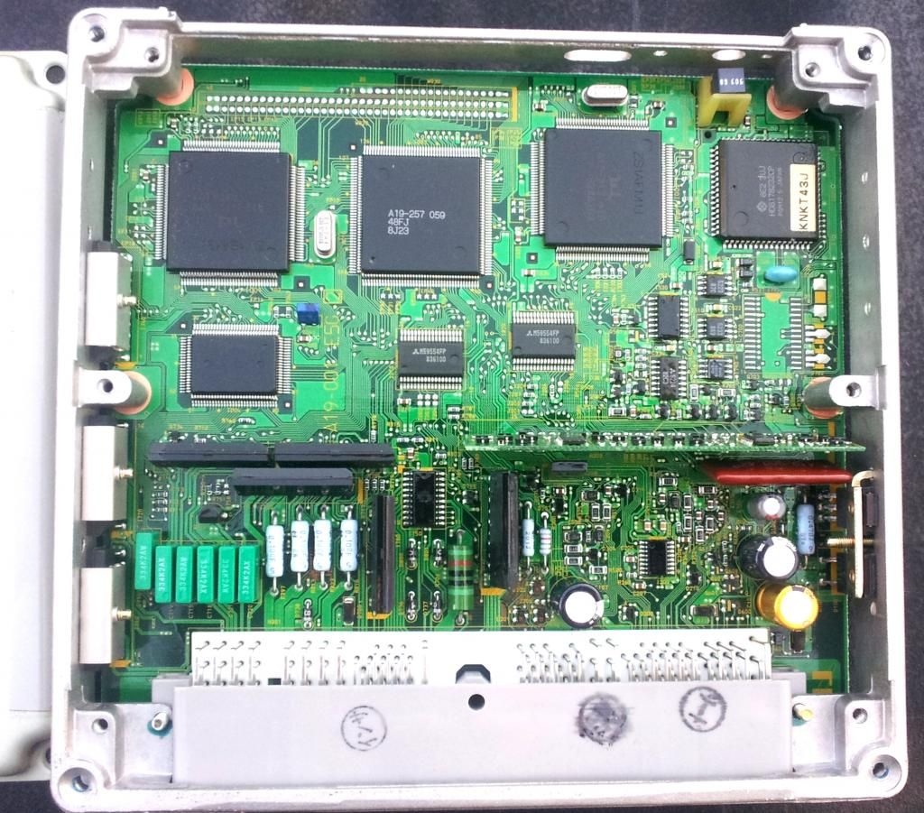
So that I don't have to screw around with the ECU, I use a $49 scan and reset tool that I picked up from Harbor Freight a few years ago.


So that I don't have to screw around with the ECU, I use a $49 scan and reset tool that I picked up from Harbor Freight a few years ago.
Last edited by CS_AR; 03-18-2015 at 07:35 PM.
03-19-2015, 03:36 PM
#9
I can peer into the ecu through the little oval hole next to the adjustment screw, and see that the screw threads into a box-like device that should be firmly attatched to the inner wall of the ecu. However this box like device is flopping around loose, but not loose enough for the face of the adjustment screw to become non-visible. I also noticed as far as wiring goes (that i can see), theres 2 wires that run to it which are both securely connected. Offhand it looks ok to me.
Id like to open the ECU for a better look but im honestly worried ill damage it or strip one of the bolts that keep it sealed. The 4 screws on each of the corners of the ecu box are absurdly tight and ill mangle them trying to get them out - is there a step to opening the ECU that im missing or are these screws meant to be torqued in so much?
But part of your problem is that Japanese phillips head screws and American phillips head screws are different, which then makes the screwdrivers different. It's the angle that the 4 slots have. If you put your screwdriver in a screw head, is there any slop or is it a snug fit? If it is not a snug fit, it will be real easy to strip the head. What I do is file down the tip of my screwdriver a little bit so it goes down further into the screw.
Once you have a screwdriver that fits the screw head snugly, you will have to press the screwdriver real hard into the screw when you turn it.
03-19-2015, 03:46 PM
#10
The potentialmeter has three leads that come off of it; 2 of them have a wire soldered on, which both loop around inside the ECU box until they connect to one of the circuit boards. This is the case in both of the ECUs i have so im fairly certain the 3rd unused lead is of zero significance. As far as being wired in correctly, the potentiometer is indeed connected correctly.
My question is with how this potentiometer is secured to the ecu box. The wiring/function/etc seems to be physically intact - just that its kinda floating somewhat freely. Is it ok for it to be flopping around a little as long as the screw turns/stops correctly and the wiring is intact?
Sorry if im being vague or non descriptive, i dont really know electrical terminology that well.
EDIT: as far as im aware, the screw/potentiometer is electrically connected via the two wires i mentioned above and nothing else - can anyone confirm this?
In CS_AR's photo, the pot (slang for potentiometer) is mounted in a holder. It sounds like your ECU doesn't have this. What you can do us open up the ECU and put a big blob of silicon adhesive on the printed circuit board and press the pot into the silicon. You want the silicone to come up the sides of the pot so that the pot is cradled by the silicon, not just touching the bottom.
03-26-2015, 11:42 AM
#11
Newbie - Just Registered
Thread Starter
iTrader: (11)
Join Date: Apr 2013
Location: Long Island, NY
Posts: 1,167
Would the lack of having the potentiometer or having it loose affect the operation of the ecu? Like would it cause any codes or make the car run in limp mode or anything of that sort?
From what i can discern, the pot is still in its holder, its just that it appears that holder is not attatched to anything. As said already, the screw still turns and stops appropiately, but is able to jiggle back and forth.
I have no desires to use the screw at all, i already have a scan tool. My only concerns are whether or not it can potentially cause a CEL or affect the cars drivability.
Again, im not really confident with opening the ecu up for a better look - the 4 corner screws that hold the top/bottom of the box together are in so tight that im afraid i might strip them trying to get them out (unless theres more to it than just these 4 screws?)
Thanks for the help so far guys, it is much appreciated.
03-26-2015, 06:24 PM
#13
Newbie - Just Registered
Thread Starter
iTrader: (11)
Join Date: Apr 2013
Location: Long Island, NY
Posts: 1,167
Thanks again. I wont be putting it in for a few weeks because i have some vacuum related issues to sort out first, but when i do ill let you all know how it works out.

Thread
Thread Starter
Forum
Replies
Last Post
litch
4th Generation Maxima (1995-1999)
123
01-04-2024 07:01 PM
tarun900
4th Generation Maxima (1995-1999)
19
12-20-2021 06:57 PM
DC_Juggernaut
7th Generation Maxima (2009-2015)
4
09-28-2015 04:07 PM