When you click on links to various merchants on this site and make a purchase, this can result in this site earning a commission. Affiliate programs and affiliations include, but are not limited to, the eBay Partner Network.
Great, thanks man. I'll have to give it another go... Maybe have someone else pulling the connector while I'm jamming down on the latch.
This subwoofer problem is definitely annoying. Really hoping that soldering the broken joints will fix it! It's strange though, my subwoofer seems to react to heat. It works far more reliably on days that it is really hot, but I barely ever hear it in the winter. I know summer is coming up, but I wanted to get this fixed once and for all. Will report back if I'm able to get the connectors off and solder the joints.
One person can disconnect that plug.
That's funny, mine seems to work better in the winter time and not when it's hot. It's definitely affected by a temperature change one way or the other. I think it's just a bad design of the circuit board. I've not yet gone in and tried any of the suggestions except to spray that connector. That wasn't it.
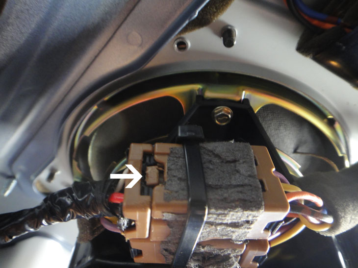
So I managed to detach the connectors. I know it's already been explained that it's the brown latch that you need to push, but I took a picture in case it helps anyone.
Note that the latch is connected to the small connector. This is important so you know how to push the latch and pull the connectors apart. I did this by jamming a pair of needle-nose pliers into the latch with my right hand, sliding a flat-head screwdriver between the connectors with my left hand, and prying them apart. Obviously you don't have to use these tools but you get the idea.
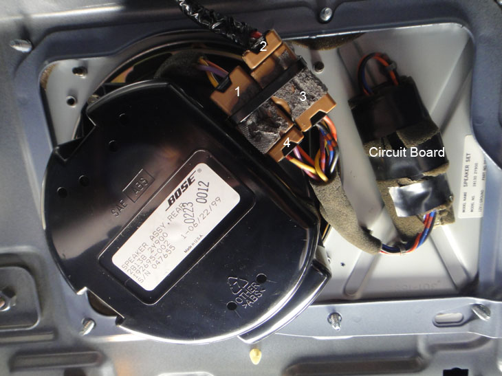
I took another picture that shows what everything looks like from inside the trunk. Note that this was post-soldering (foam around the brown connectors and circuit board have been ripped).
After I had detached the connectors, I remove the circuit board, opened it up, and attempted to solder the joints with a Cold Heat soldering iron and lead-free solder. I didn't know anything about soldering, but I found out that this was a mistake. The Cold Heat took way too long to heat things up, and lead-free solder has a higher melting point. In the end, I managed to break the tip of the Cold Heat before I could solder any joints, and I think I ended up doing more damage to the joints.
If you do want to attempt the soldering procedure, I recommend going to Radioshack and picking up this $10 soldering kit. Very simple but it did the trick, and it even comes with some 60/40 solder (which has a lower melting point). I was able to solder the joints very quickly. I re-installed the circuit board, but to my dismay, the subwoofer still wasn't working. What's more, my subwoofer would no longer turn on on really hot days (like it used to). I'm fairly certain this is because of damage I did with my first attempt with the Cold Heat.
After reading more posts in this thread, I decided to simply remove the circuit board altogether and connect the amp directly to the subwoofer. It's rather easy, and is explained in earlier posts, but for anyone who wants a picture, see the one above. Simply detach connectors 3 and 4, and connect 2 with 1. Just like that, your subwoofer will be working again if the circuit board is in fact the problem. Side effects for me include the thump upon powering up and a thump or two several seconds after powering down. A small price to pay for a working subwoofer. I'm not sure if removing the circuit board will cause any kind of damage to the subwoofer, but at this point I don't really care anymore.
This post is longer than I intended, but just wanted to share my experience. Thanks to everyone in this thread for the help.
Random note for anyone attempting the soldering procedure: Step 1 is basically an overview of what you must do, not something you must do before Step 2. This confused me at first. Just start at Step 2.
So I managed to detach the connectors. I know it's already been explained that it's the brown latch that you need to push, but I took a picture in case it helps anyone.
Note that the latch is connected to the small connector. This is important so you know how to push the latch and pull the connectors apart. I did this by jamming a pair of needle-nose pliers into the latch with my right hand, sliding a flat-head screwdriver between the connectors with my left hand, and prying them apart. Obviously you don't have to use these tools but you get the idea.
I took another picture that shows what everything looks like from inside the trunk. Note that this was post-soldering (foam around the brown connectors and circuit board have been ripped).
After I had detached the connectors, I remove the circuit board, opened it up, and attempted to solder the joints with a Cold Heat soldering iron and lead-free solder. I didn't know anything about soldering, but I found out that this was a mistake. The Cold Heat took way too long to heat things up, and lead-free solder has a higher melting point. In the end, I managed to break the tip of the Cold Heat before I could solder any joints, and I think I ended up doing more damage to the joints.
If you do want to attempt the soldering procedure, I recommend going to Radioshack and picking up this $10 soldering kit. Very simple but it did the trick, and it even comes with some 60/40 solder (which has a lower melting point). I was able to solder the joints very quickly. I re-installed the circuit board, but to my dismay, the subwoofer still wasn't working. What's more, my subwoofer would no longer turn on on really hot days (like it used to). I'm fairly certain this is because of damage I did with my first attempt with the Cold Heat.
After reading more posts in this thread, I decided to simply remove the circuit board altogether and connect the amp directly to the subwoofer. It's rather easy, and is explained in earlier posts, but for anyone who wants a picture, see the one above. Simply detach connectors 3 and 4, and connect 2 with 1. Just like that, your subwoofer will be working again if the circuit board is in fact the problem. Side effects for me include the thump upon powering up and a thump or two several seconds after powering down. A small price to pay for a working subwoofer. I'm not sure if removing the circuit board will cause any kind of damage to the subwoofer, but at this point I don't really care anymore.
This post is longer than I intended, but just wanted to share my experience. Thanks to everyone in this thread for the help.
Random note for anyone attempting the soldering procedure: Step 1 is basically an overview of what you must do, not something you must do before Step 2. This confused me at first. Just start at Step 2.
CONGRADS:
Ha, well if it makes you happy then I guess that's all that counts. That poping noise that you mention may in time separate your speaker coil from the cone. I think the circuit board with the relay on it acts as a on - off and filter to prevent the poping.
I myself have not yet attempted any kind of fix and for now I'm just waiting for winter.
Is this seriously helps xause on my 00 I looked at the board and it looks good nothing is lose or broken. Should I still solder them anyway mines looks a little different than that pic on the first post. Mine has some extra
Reviving an old thread. I just took out my relay/filter in my 2000 I30, resoldered it and reinstalled it, sub is working again. My only question is whether or not my relay is actually functioning 100%. I mean, it's an electromechanical switch, not too complicated, it's either on or off, but I noticed that there is a very soft "thud" sound when I turn the ignition on, even with the relay still in place.
Most people mentioned that there is a loud "thud" when they turn on their ignition with the relay bypassed, is it supposed to be totally silent with the relay in place? Again, it went from not working to working, so obviously my resoldering worked, but is there such a thing as maybe one of the pins in the relay not contacting, or the relay being internally shorted permitting it to still pass through the thud, or is it just that I am listening too sensitively for it? Looking at the relay box, I don't see anything that looks like a low pass filter, but many were mentioning that the little relay circuit board contains one...I just don't want to be sending full range input to the sub, the voice coil isn't really designed for those frequencies, plus, it would just sound worse anyway.
To the best of my knowledge it does sound as though my sub is rolling off high frequencies (compared with bypassing the relay circuit), but I do have a very quiet "thud" when turning on the ignition, if I remember correctly my old 2003 Maxima did the same thing, perhaps they are not completely silent? Is there any quick way of checking?
I believe that relay supplies power to the woofer amp. The popping is not good for the speaker coil. My '94 did that but I think there was a bad capacitor somewhere. On my 03 I have the same problem with the woofer not working. It seems to like only cold temperatures before it will allow me to enjoy the boom.
I tried re soldering the connections but it didn't help. I do know how to solder very well too. I believe on some of these that the relay is bad.
I fixed my wifes by jumping the connection as explained here in a thread describing the 01,02 and 03 cars. https://maxima.org/forums/5th-genera...-once-all.html
The concept is the same only the relay is in the harness on the 2000 cars and not on the main board inside the box.
This lets the rest of the components on that board to do their job so there's no popping or stray signals that come from bypassing it.
Here are some pics. I didn't remove the relay. I just jumped it from the back of the board with the relay in place.
so basically you figured out how to bypass with out getting a new relay on a 2002 like others have done on the 2000 and 2001 ?
i replaced the relay my 2002. on the 2002 and 2003 the bypass relay trick doesnt work since it is different,
I can't take any credit for figuring it out. I just collected info from a few other threads on the subject.
I did it to the wifes 00 and my 02 at the same time and the bypass trick worked on both cars. Neither car had a working sub for a while before that. The only difference between 00-03 seems to be that the 00 cars have the relay on the small board and the 01-03 cars have it inside on the main board. Either way, the relay works the same.
I've read several threads that deal with the intermittent and sometimes terminal Bose woofer cut off problem, woofer stops working. Some have identified what was thought to be the cause of the problem; little black box shorted, bad connectors, amp not working, and etc. All are good probable causes but none seemed to really nail down the problem and in turn provide a repair that absolutely corrected the problem without removing or modifying parts or having the problem return.
In any case, this is my humble attempt to provide a definitive cause and solution that eliminates the problem for the 2000 Maxima.
The harness and circuit board pictured below appeared to have no continuity problems. I then examined the circuit board under a magnifying glass and found the 5 soldered joints that are circled in the last picture which connect the little black box to the circuit board were all broken. I could barely see the broken joints. I re-soldered each joint. This has eliminated the woofer cut off problem.
Repair Procedure
Remove the harness in the picture below which is located on the side of the woofer housing(do so by sliding the two connectors off of the black housing of the woofer)
Slide the zip tie off of the two joined connections
Unplug the 2 connectors
Remove the harness by detaching the 2 tie downs from the base that the woofer is attached to (do this by removing the woofer grill on the rear parcel shelf and pushing the tie downs through their holes)
Carefully cut through the foam and plastic cover under the foam to fully expose the circuit board (see picture below)
Re-solder the joints circled in the picture below
Recover circuit board with plastic and foam
Re-install part
This worked perfectly for me. Thank you very much for the instructions.
 05-21-2012, 09:05 AM