What can cause the SES not to work?
 10-04-2015, 02:02 PM
#41

Thanks for the info. But I think you may have the numbers reversed left & right. You said
3 6
5 7
1 2
The reason I think it should be
6 3
7 5
2 1
is because of the voltage readings you got when the car was running. The last voltage you recorded was .9 volt. This should be the reading on pin 1 that is grounded by the ECU to energize the relay.
So with the pin numbering information and looking at the voltage readings of when the car was NOT starting, here is what you had:
pin 1 - 0.4.
pin 2 - 0.4
pin 3 - 0.41
pin 5 - 1.32
pin 6 - 12.0
pin 7 - 0.01
Referring to the relay wiring diagram (EC-156), relay pins 2, 3 and 6 should ALWAYS have 12 volts on them as they are connected to fuses straight from the battery. Pins 2 and 3 are missing the 12 volts that comes from fuse # 59 (ENG CONT 2). Without 12 volts on pin 2, the relay cannot be energized as it needs to be for the car to work properly.
So I think my earlier assumption (bottom of post # 39) about problems in the fuse panel has some re-enforcement now.
You can put a jumper wire from the battery (or any non-switched 12 volt spot) and connect it to the relay pin 2. You would also need to jumper 12 volts to pin 3, but I am hoping the wire harness jumper is still good, however, don't assume this. Use a voltmeter to check it. You can test this more easily with the relay unplugged. Put the jumper into pin 2 of the socket and measure for voltage on pin 3.
 10-04-2015, 02:27 PM
#42


Thanks for the info. But I think you may have the numbers reversed left & right. You said
3 6
5 7
1 2
The reason I think it should be
6 3
7 5
2 1
is because of the voltage readings you got when the car was running. The last voltage you recorded was .9 volt. This should be the reading on pin 1 that is grounded by the ECU to energize the relay.
So with the pin numbering information and looking at the voltage readings of when the car was NOT starting, here is what you had:
pin 1 - 0.4.
pin 2 - 0.4
pin 3 - 0.41
pin 5 - 1.32
pin 6 - 12.0
pin 7 - 0.01
Referring to the relay wiring diagram (EC-156), relay pins 2, 3 and 6 should ALWAYS have 12 volts on them as they are connected to fuses straight from the battery. Pins 2 and 3 are missing the 12 volts that comes from fuse # 59 (ENG CONT 2). Without 12 volts on pin 2, the relay cannot be energized as it needs to be for the car to work properly.
So I think my earlier assumption (bottom of post # 39) about problems in the fuse panel has some re-enforcement now.
You can put a jumper wire from the battery (or any non-switched 12 volt spot) and connect it to the relay pin 2. You would also need to jumper 12 volts to pin 3, but I am hoping the wire harness jumper is still good, however, don't assume this. Use a voltmeter to check it. You can test this more easily with the relay unplugged. Put the jumper into pin 2 of the socket and measure for voltage on pin 3.
3 6
5 7
1 2
The reason I think it should be
6 3
7 5
2 1
is because of the voltage readings you got when the car was running. The last voltage you recorded was .9 volt. This should be the reading on pin 1 that is grounded by the ECU to energize the relay.
So with the pin numbering information and looking at the voltage readings of when the car was NOT starting, here is what you had:
pin 1 - 0.4.
pin 2 - 0.4
pin 3 - 0.41
pin 5 - 1.32
pin 6 - 12.0
pin 7 - 0.01
Referring to the relay wiring diagram (EC-156), relay pins 2, 3 and 6 should ALWAYS have 12 volts on them as they are connected to fuses straight from the battery. Pins 2 and 3 are missing the 12 volts that comes from fuse # 59 (ENG CONT 2). Without 12 volts on pin 2, the relay cannot be energized as it needs to be for the car to work properly.
So I think my earlier assumption (bottom of post # 39) about problems in the fuse panel has some re-enforcement now.
You can put a jumper wire from the battery (or any non-switched 12 volt spot) and connect it to the relay pin 2. You would also need to jumper 12 volts to pin 3, but I am hoping the wire harness jumper is still good, however, don't assume this. Use a voltmeter to check it. You can test this more easily with the relay unplugged. Put the jumper into pin 2 of the socket and measure for voltage on pin 3.
When the car was in a no start condition I can tell you that I check both the engine cont fuses. Both of them showed battery voltage, one of those goes to the top left spot on the relay which should be 3/purple wire, and that shows battery voltage. The I have not traced the wire on the other engine cont fuse. Again, I am not very good with reading wiring diagrams so I could have things mixed up.
10-04-2015, 06:30 PM
#43
Yes, you do have the pin numbering confused. Some of this confusion about pin numbers may stem from believing the numbers that are on the diagram molded into the top of the relay. This diagram is not correct. It is left/right backwards. I should have given you a warning on this, but I forgot about the diagram. If you remove the relay from the socket and look on the bottom of the relay, you will see that the numbers do not match what is on top.
You said that you had 12 volts on the top left and it was a purple wire. That part is correct, but that is not pin 3. The purple wire is on pin 6 and the power comes from a different fuse then the one I am suspect about. Based on your voltage readings in post # 38, pin 6 is OK. Pin 3, a white/blue stripe wire, was almost zero when it should have been 12 volts.
I am trying to understand how you are working on the relay to take the voltage readings. What I am now thinking is that you are getting the voltage readings off of the bottom of the relay. You have probably loosened the whole relay box so that you can turn it over. So assuming you are looking at the bottom of the relay and can see the wires and their colors, here is a list of the relay pins and the color if the wire that is connected to it.
pin 1 - white/red stripe - goes to ECM pin 38
pin 2 - white/blue stripe - comes from fuse ENG CONT 2
pin 3 - white/blue stripe - comes from fuse ENG CONT 2
pin 5 - red/green stripe - goes to ECM pins 110 & 112
pin 6 - solid purple - comes from fuse ENG CONT 1
pin 7 - red/white stripe - goes to ECM pin 31
Again, you should always have 12 volts on pins 2, 3 and 6 because these pins are connected to the battery.
When the car has been started and is running, pins 5 and 7 will have 12 volts on them. Pin 1 will be less than 1 volt.
You said that you measured 12 volts on both fuses. I expected that. What I am thinking is that when the power comes out of the ENG CONT 2 fuse and is supposed to go to the relay, there is a loose connection on the bottom of the fuse panel that keeps this from happening. A loose/bad connection will let you measure 12 volts on the fuse, but at the relay, the white/blue stripe wire on pins 2 and 3 will be zero.
Trying to keep track of what pins are what numbers is pretty hard when you are twisting in every direction trying to get to it and take a voltage reading. Are you looking from the bottom, are you looking from the top, the left, the right just makes it that much tougher. Just go slow, double check have patience.
10-05-2015, 07:31 AM
#44
Thanks for the reply Dennis, and you are correct. I have flipped over the relay block so I can probe the terminals from the bottom while plugged in. You are also right I am giving pin numbers based on the top of the relay cover and what the FSM shows for a brown relay. I will pull the relay to see what the bottom of the relay says as for pin locations. Thanks for all of the help so far, you seem to have a better understanding of this stuff than I do.
10-05-2015, 10:13 AM
#45
Do pins 2 and 3 (both white/blue stripe) feed anything else other than the ecu relay? The reason that I ask is because it seems that if this circuit is the problem it would probably be easier to run a 15 amp fused line to the battery and hook them to these two terminals rather than chasing down a bad piece of wire some where. Thoughts?
10-05-2015, 10:18 AM
#46
You are dealing with a problem that is not very common at all. So the learning curve needed to do this kind troubleshooting takes months, so first time out is going to be tough. As I said earlier, have patience, go slow and double check things.
The fact that you want to get things cleared up in you mind tells me that you will get this problem solved.
The fact that you want to get things cleared up in you mind tells me that you will get this problem solved.
10-05-2015, 07:18 PM
#47
Made some progress! So to start out I removed engine cont 2 fuse, and when I did this I could replicate my no start/no SES light problem, so I knew we were on to something. I previously did not mess with this fuse because I removed the engine cont 1 fuse and it did not replicate the problem...so I did not even try the engine cont 2 fuse. Finally after letting the car run for an hour it finally failed. I had my alligator clip jumper in place and as soon as I put 12 volts on the white/blue stripe pin 2 the car came back online. Also when I added voltage to the number 2 pin I probed pin 3 (the other white/blue wire) and sure enough it had voltage, and the car fired right up with out a problem.
So I think we have found the cause of the problem, but now my question is how to best fix it. When the wires coming from pins 2 and 3 on the relay the come off of the relay and go into a harness that goes towards the right side of the car, under the upper radiator support...so I am not sure where they go. So I am not sure if the problem is somewhere down the line or at the fuse box. Which of the three following solutions would be the best?
1) cut the engine cont 2 wire from the bottom of the fuse box and run a fused line from the battery to that wire...basically replicating what is there but cutting the oem fuse box out of this circiut?
2) Cut the wires coming off pin 2 and 3, and tie those together and then run a fused line coming off the battery to under the relay box and hook the three wires together creating a new circiut with only these two pins on it. This would leave the OEM engine cont 2 circiut intact with these two pins cut out. I have considered this way since I don't know where else the oem wires go when they go across the upper radiator support.
3) Leave the oem engine cont 2 circiut intact and just "T" in a 12v fused line coming off of the battery to the bottom of the fuse box. Not cutting anything out just adding a fused line coming off the battery. I am considering this just to leave the factory circiut intact but adding a back up 12 volt source.
These are the three options I have though of? Any comments or another idea of how to do this better?
10-06-2015, 03:34 AM
#48
All right! This is excellent news.
However, I am not particularly fond of any of the fixes you mentioned. The reason being is that I don't like extra wires under the hood (or anywhere for that matter). I view these as a last resort fix. I think with a little more work, you can find the actual point of the problem, fix it and have a nice, clean under-hood appearance.
You know that the wires for pins 2 and 3 of the relay go to/come from the fuse. So the wires in the wire harness will go back to the fuse panel. Feel along the wire harness and see if you can detect any damage such as cuts or nicks that could have damaged/cut wires.
If no damage to the wire harness, then disconnect the battery and remove the fuse panel and look at the underside. Another person on the org here said that there are screws that can come loose and cause intermittent electrical problems. I have never done this, so I don't know if this is true or not. So look for screws and check that they are tight. Also, look that the bottom of the ENG CONT 2 fuse where the blue/white stripe wire attaches to it. Check that the wire is attached solidly. Another thing to check is that the metal contact piece that the fuse plugs into grips the prong of the fuse tightly.
If you can't find any problems in the fuse panel, then I would say go with your choice # 3.
But I do have to say that you have done one hell of a job with this. How you figured out that the relay was part of the problem is amazing. Good work.
10-06-2015, 06:39 AM
#49
All right! This is excellent news.
However, I am not particularly fond of any of the fixes you mentioned. The reason being is that I don't like extra wires under the hood (or anywhere for that matter). I view these as a last resort fix. I think with a little more work, you can find the actual point of the problem, fix it and have a nice, clean under-hood appearance.
You know that the wires for pins 2 and 3 of the relay go to/come from the fuse. So the wires in the wire harness will go back to the fuse panel. Feel along the wire harness and see if you can detect any damage such as cuts or nicks that could have damaged/cut wires.
If no damage to the wire harness, then disconnect the battery and remove the fuse panel and look at the underside. Another person on the org here said that there are screws that can come loose and cause intermittent electrical problems. I have never done this, so I don't know if this is true or not. So look for screws and check that they are tight. Also, look that the bottom of the ENG CONT 2 fuse where the blue/white stripe wire attaches to it. Check that the wire is attached solidly. Another thing to check is that the metal contact piece that the fuse plugs into grips the prong of the fuse tightly.
If you can't find any problems in the fuse panel, then I would say go with your choice # 3.
But I do have to say that you have done one hell of a job with this. How you figured out that the relay was part of the problem is amazing. Good work.
However, I am not particularly fond of any of the fixes you mentioned. The reason being is that I don't like extra wires under the hood (or anywhere for that matter). I view these as a last resort fix. I think with a little more work, you can find the actual point of the problem, fix it and have a nice, clean under-hood appearance.
You know that the wires for pins 2 and 3 of the relay go to/come from the fuse. So the wires in the wire harness will go back to the fuse panel. Feel along the wire harness and see if you can detect any damage such as cuts or nicks that could have damaged/cut wires.
If no damage to the wire harness, then disconnect the battery and remove the fuse panel and look at the underside. Another person on the org here said that there are screws that can come loose and cause intermittent electrical problems. I have never done this, so I don't know if this is true or not. So look for screws and check that they are tight. Also, look that the bottom of the ENG CONT 2 fuse where the blue/white stripe wire attaches to it. Check that the wire is attached solidly. Another thing to check is that the metal contact piece that the fuse plugs into grips the prong of the fuse tightly.
If you can't find any problems in the fuse panel, then I would say go with your choice # 3.
But I do have to say that you have done one hell of a job with this. How you figured out that the relay was part of the problem is amazing. Good work.

One thing that has made this problem drag on forever is that it takes a while to replicate the car failing (i.e. the car ran for an hour last night before it would cut off). So when the car will not fail I cannot test anything...so this has been super time consuming. I would have been much easier to figure out if the car would cut off as soon as I started it.
*I may test the bottom side of the fuse panel before I try to do a patch, with out unhooking more stuff the fuse panel is hard to flip over, and you need to take the battery out to do it. But I can use one of my alligator clips hooked to the bottom of the blue/while line coming out of the bottom of the fuse panel as a cheater point to test that line when it fails since I cannot easily access the bottom of the fuse panel while the car is running (battery installed)*
Here are a couple of pictures just to show what I am working on. here is how I was jumping voltage down to the relay when it failed.

 10-06-2015, 08:41 AM
#50
Having been in situations like you got dumped on, I understand your wanting to be done with it.
I was voicing my personal opinion. Being your car, all I can do is put my .02 in. And I did. But the main thing is that you found the problem and kudos to you. Finish up the details and you can go back to happy driving.
I was voicing my personal opinion. Being your car, all I can do is put my .02 in. And I did. But the main thing is that you found the problem and kudos to you. Finish up the details and you can go back to happy driving.
10-12-2015, 10:49 AM
#51
So just for curiosity sake I started the car up over the weekend (have not done a repair yet) and let it run until it died and the CEL would not come on and the car would not start. I checked voltage on top of the engine cont 2 fuse and it had 12 volts. So then I had a jumper plugged into the bottom of the fuse box where this wire attaches...I was trying to figure out if the problem is in the fuse box or somewhere down the line. The bottom of the fuse box also had 12 volts. So I think it is safe to assume the problem is somewhere else down the line.
So I wired up my fix...fused line from the battery down to the white/blue wire in the relay. I cut the white/blue wire in half and then twisted it together with the line coming from the battery, so that I would just be adding 12 volts to this circuit. At this point I had not put the fuse in the fuse holder in the line coming off the battery and the car still would not start, but as soon as I put the fuse in everything came online and the car fired right up!
Here is a picture kinda showing what I did.
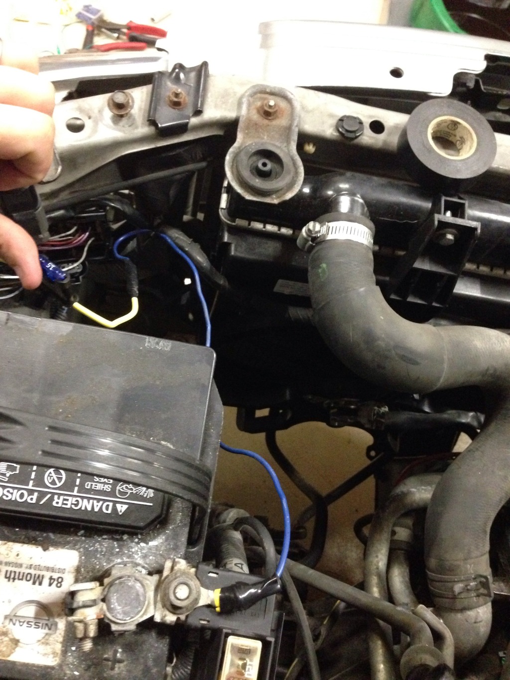


Thread
Thread Starter
Forum
Replies
Last Post
jerrod99_se-l
4th Generation Classifieds (1995-1999)
2
08-27-2015 08:27 PM