HOW TO: Add aux to stock bose...
 10-30-2007, 09:37 AM
#161
Member

Join Date: Jul 2003
Posts: 160
I'd like to do something similar, like when I turn on the XM receiver, it puts the radio in AUX mode. Turn off the XM receiver, back to normal. Wife has already complained a couple times about having to flip a switch. Of course, she used to complain about fuzzy XM reception when she drove into different areas and the FM frequency needed to be changed, so whatever.

 11-08-2007, 07:13 PM
#163
Junior Member

Join Date: Feb 2007
Posts: 25
So here's a few thumbs if anyone can take a look. This is the underside of the bose in a 2001. I can't figure out where to hook up my inputs and switches. Feel free to ask for closer shots.
http://img.photobucket.com/albums/v2...0/PICT0117.jpg
http://img.photobucket.com/albums/v2...0/PICT0116.jpg
http://img.photobucket.com/albums/v2...0/PICT0115.jpg
http://img.photobucket.com/albums/v2...0/PICT0114.jpg
http://img.photobucket.com/albums/v2...0/PICT0113.jpg
So I'm having trouble tagging from Picasa. These are from Pbucket, and it doesnt do thumbs. I'll make a prettier post soon, in the mean time, PLEASE take a look and help us 01 owners out!
Last edited by gotcha640; 11-08-2007 at 07:59 PM. Reason: Photo trouble
11-09-2007, 01:22 PM
#164

The picture that is suposed to show what wires hook too what is missing. Can someone give me a written description of how to do this, or if someone has the picture maybe put it back up. thanks
11-09-2007, 07:51 PM
#165
Junior Member

Join Date: Sep 2007
Posts: 99
Look here: http://ryft.org/index.php?title=1995...Bose_HU_AUX_in
Thats a more detailed write up I did. needs better pictures, but you should see what you need to do.
Could an admin edit the first post to include that link?
Thats a more detailed write up I did. needs better pictures, but you should see what you need to do.
Could an admin edit the first post to include that link?
12-14-2007, 08:41 AM
#166
Member

Join Date: Nov 2007
Location: Coram, NY
Posts: 64
I'm an EE tech at a company in medford, NY (long island). My boss loves when i bring in projects to play with, so I'm going to work on that cdchanger button fix instead of needing that extra switch, I have an idea *evil laugh*
01-30-2008, 02:09 PM
#168
Member

Join Date: May 2006
Posts: 90
does anyone know what the radio needs to see from the CD changer to let you use that button??? is it a simple ground or something????
There should be away to wire it up and beable to press the CD changer button to listen to your AUX.....instead of the extra switch
There should be away to wire it up and beable to press the CD changer button to listen to your AUX.....instead of the extra switch
01-30-2008, 02:35 PM
#169
Member
Join Date: May 2006
Posts: 90
for the 98 BOSE you take and install a switch between the AUX-ON and the RX wires correct?
What does this actually do??? Is the AUX-ON power??? I'm trying to figure out how i can wire in my Sirius and have the sirius be the switch. thanks
What does this actually do??? Is the AUX-ON power??? I'm trying to figure out how i can wire in my Sirius and have the sirius be the switch. thanks
Last edited by 05AltimaSER; 01-31-2008 at 09:50 AM.
03-20-2008, 07:18 AM
#170
Newbie - Just Registered

Join Date: Mar 2008
Posts: 2
Has anyone successfully gotten this to work by pressing the CHG button instead of using the switch? I have the AUX switch working but I would like it all to come from the HU.
I know this is possible since using the XIA-I01 interface allows you to do this.
This is on a Clarion system but the pin layout is exactly the same as the Bose.
I know this is possible since using the XIA-I01 interface allows you to do this.
This is on a Clarion system but the pin layout is exactly the same as the Bose.
03-20-2008, 08:43 AM
#171
Member
Join Date: Nov 2007
Location: Coram, NY
Posts: 64
I believe that the bose unit communicates with the cd changer via a serial type protocol, so the only way to get the changer button to work is to actually make cuts and jumps on the board, along with creating a latching type circuit that the button would drive.
03-20-2008, 09:45 AM
#172
Newbie - Just Registered
Join Date: Mar 2008
Posts: 2
I am basing this on the fact that you can buy the XIA-I01 interface and use the CHG button to switch it to whatever you have plugged into the RCA outputs on the interface and depending on the year of the car actually have some control of the aux unit (for lack of a better term) say and ipod or something else. Therefore, everything you need signal wise is in the CDChanger connector. I am using the harness that is made for the XIA-I01 which has almost everything wired (except for AUX ON and Combi ON which I soldered and wired).
This post, although for a different radio, helps to reinforce my belief.
http://nodivisions.com/tech/kenwood_aux_adapter/
I figure the same rules apply for the most part to these HU's.
CHG button has to "sense" something is there before it can use it, and make it an input device to route audio from it to the head unit.
04-28-2008, 07:53 AM
#173

Old Thread Bump... Requesting someone post pictures of their 99 Bose Aux Connection.
I don't need a picture of the front faceplate saying aux or whatever, I need a picture of what pins you soldered on there.
I'm still confused on how to solder my aux wires on there and where to find the two pins to short together to force aux mode.
I don't need a picture of the front faceplate saying aux or whatever, I need a picture of what pins you soldered on there.
I'm still confused on how to solder my aux wires on there and where to find the two pins to short together to force aux mode.
06-15-2008, 09:37 PM
#174
Member

Join Date: Apr 2005
Posts: 49
Does any still have the file "Matts_Nissan_Bose_Aux_Input_Circuit.pdf" ? if you do, please email it to me at rymoto@gmail.com
Thanks
Thanks
11-07-2008, 09:13 PM
#176
Newbie - Just Registered

Join Date: Sep 2007
Posts: 9
Installing Aux on Bose Cracked Faceplate
Anybody have a spare for a 1996 Bose unit? I broke the small outer faceplate that surrounds the volume and tone *****. I am also working on a CHG button driven latching circuit for the AUX.
 11-13-2008, 09:10 PM
#178
so the mod took me about an hour, all set and done it works great. i did however broke my spring for the the slide out tray under the radio. i was modding it so i can run the cables into it and i didn't realize there was a spring there and completely stretched it. i sorta fixed it but now it only comes out half way and i have to pull it out the rest.... o well
11-15-2008, 09:48 AM
#179

So here's a few thumbs if anyone can take a look. This is the underside of the bose in a 2001. I can't figure out where to hook up my inputs and switches. Feel free to ask for closer shots.
http://img.photobucket.com/albums/v2...0/PICT0117.jpg
http://img.photobucket.com/albums/v2...0/PICT0116.jpg
http://img.photobucket.com/albums/v2...0/PICT0115.jpg
http://img.photobucket.com/albums/v2...0/PICT0114.jpg
http://img.photobucket.com/albums/v2...0/PICT0113.jpg
So I'm having trouble tagging from Picasa. These are from Pbucket, and it doesnt do thumbs. I'll make a prettier post soon, in the mean time, PLEASE take a look and help us 01 owners out!
http://img.photobucket.com/albums/v2...0/PICT0117.jpg
http://img.photobucket.com/albums/v2...0/PICT0116.jpg
http://img.photobucket.com/albums/v2...0/PICT0115.jpg
http://img.photobucket.com/albums/v2...0/PICT0114.jpg
http://img.photobucket.com/albums/v2...0/PICT0113.jpg
So I'm having trouble tagging from Picasa. These are from Pbucket, and it doesnt do thumbs. I'll make a prettier post soon, in the mean time, PLEASE take a look and help us 01 owners out!
12-04-2008, 08:17 AM
#180
Member

Join Date: Feb 2003
Location: Chicago IL
Posts: 176
okay, this looks awesome, but I can't find whether or not this will work on a 2002 bose in-dash changer HU. please let me know if it does, or if anyone knows. thanks in advance
Last edited by tkostiuk4; 12-04-2008 at 12:23 PM.
12-06-2008, 09:54 PM
#181
Newbie - Just Registered

Join Date: Oct 2008
Location: Brooklyn, NY
Posts: 5
 02-02-2009, 08:16 PM
#182
For 95-96 Bose why do we have to install a switch between the AUX-ON and GND? I installed a switch between AUX-ON and RX just like the 97-98 units and get AUX mode. I tested 3 different units and there all the same. I even found a factory plug that fits so no opening up the radio and soldering on the circuit board.
02-04-2009, 03:19 PM
#183

Maury
 02-05-2009, 12:07 PM
#185
Bad news for 2K2 max, and help needed
I tore apart my 2K2's Bose HU and could not get to the circuit board. I removed 2200 screws and still could not get the CD changer separated from the HU, in order to get a clean look at the solder connections.
I buttoned it back up and thought I might try intercepting the tape deck leads at the white multi-pin connector as it goes IN to the HU. Problem #1, you can't select TAPE as an input unless there's a tape IN THE DECK. That option is out. Problem #2, I thought I could piggy-back into the CD player leads, and maybe by leaving at least 1 blank CD in the changer, that would work. Still not sure if that plan will bear any fruit - I disconnected the 10-pin white connector and all 10 wires are now loose and no longer in their correct arrangement. Can anyone here tell me how to arrange these wires again? Red, Yellow, White, Green, Green & White, Purple, Red & White, Black, Gray, Red& Yellow.
Here's a pic of the black connector that I need to feed these colors into. Thanks in advance for any help.
http://picasaweb.google.com/mauryrut...08545381787778
Maury
Last edited by Maury; 02-05-2009 at 12:14 PM.
02-05-2009, 06:10 PM
#186
Been all over the internet and found 3 very helpful pictures describing "which colors go where" in the factory wiring harness for my car... and all 3 were wrong. The service manual I bought & downloaded describes which pins carry which connections, but it is not color coded. Fun stuff.
 02-09-2009, 05:27 AM
#188
02-12-2009, 01:32 PM
#190
update
UPDATE: I went to my closest Nissan dealer (an hour away) in the hopes that they would correctly diagnose this. I called them Tuesday and told them I checked the fuses and they were not the problem. I needed them to give it a thorough inspection and do their magic- the stuff only a Nissan dealer could do. Well I got there today at 9am, and at 9:30 they said "we checked the obvious - the fuses and the dimmer switch, and its not that. This is too big a job for us today, can you come back tomorrow or another time?" I reminded him that a) I live an hour away and b) the only reason I came here was for you to thoroughly inspect it!" Why the hell would I call a dealer, and set up an appointment for him to check the same fuses that have already been checked, and then give up after a half hour???"
Plan D- going to my local Ford dealer Monday (10 minutes from my house) They claim they have the Maxima wiring info and they'll help me. We'll see.
In the meantime, Autozone #3 recommended I try swapping the "AC always on" and "AC only on when the key is turned" wire, but that did not fix it.
For the record, I have discovered new symptoms too. My sunroof works now - even when the key is not in the car. Same with the power windows- they work all the time, even after I turn the car off and take the key out.
02-17-2009, 04:56 PM
#191
Thank you all SO much for your help and patience. www.justanswer.com expert "Nissan tech" helped me diagnose this and in the end it was the dimmer switch after all. Ken Pollack Nissan in Wilkes-Barre, PA charged me $30 for 1/2 labor time last week to tell me it was NOT the dimmer. $30 was hardly a big deal, but their misinformation kept so many people from truly helping me resolve this. The tech at JustAnswer.com suggested I test for power coming out of the instrument cluster. It was easier for me to buy a junkyard cluster and try that, but after that didn't work, NissanTech guided me through a multimeter test and now we're all done. WooooHooooooo!!!!
02-18-2009, 04:00 PM
#192
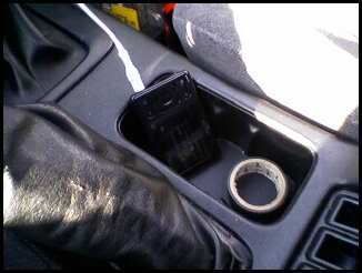
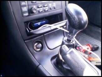
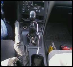
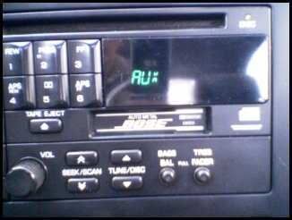
My Setup
I figured I would show my AUX. Input setup. I still need to get a bracket for my mp3 but you get the idea. They're just crapy cell phone pics but you can see what I have done. Circuit City closing FTW and FTL. I got this mp3 for $20 with radio and video capabilities, but bad because so many people lost thier jobs.
Last edited by 96nismoSE; 02-18-2009 at 04:03 PM.
03-06-2009, 10:34 PM
#193
Newbie - Just Registered

Join Date: Dec 2008
Location: Canada, Eh!
Posts: 1
Dan you are Jedi. I just did this mod today on my 97 and it works like a charm. The hardest part was removing the HU from the car. I wish I would have remembered my camera while I was working on it.
Thank you very much.
Thank you very much.
03-14-2009, 09:47 PM
#194
Newbie - Just Registered

Join Date: May 2006
Posts: 8
I've got my stock Bose with 6 CD changer from my 2K2 Maxima all apart in my work bench. In one corner of the motherboard, there are 8 solder holes that are solder filled, and the labels says AUX ON, L(-), L(+), AUX REQ, R(-), R(+), AUX REQ, COMBI ON, and N.C. So it seemed to me that BOSE HU already have the capability to have AUX INPUT.
I am going to solder 3 coax cables (for example one coax will have its center to L+ pad, and the shielding to the L- solder pad) to the these holes and route the wires out and figure out later on how to connect these to my iPod.
One I am quite concerned is that looking at this printed circuit board with a strong light, there are several circuit components missing. I think there is a label for R207 and R207 that bridge a connection between the L+ and L-, as well as R+ and R-. I think this is just a loading resistors so these input signals have some sort of loading. Also, does anyone know if the AUX ON and AUX REQ if connected together will force the unit into AUX input mode? Anyone care to Comment?
03-15-2009, 09:49 AM
#195
Junior Member

Join Date: Feb 2009
Location: Mansfield, OH
Posts: 18
03-17-2009, 06:07 AM
#196
Newbie - Just Registered
Join Date: May 2006
Posts: 8
My 2k2 HU circuit board looked different with different pin outs. I'll take a picture and post it later tonight.
Based on my tracing these signals, does my Bose generate baseband/low voltage audio signal which are then amplified at box in the bottom side of the rear deck near the rear speakers?
If that is so maybe I can tap out the HU output at the connector and use a "disconnect pins of a 1/8 inch plug that Radio Shack sells (it has a 5 pins two f which would disconnect the L/R input when a plug is inserted).
03-21-2009, 12:45 PM
#197
Newbie - Just Registered
Join Date: May 2006
Posts: 8
Bose 6CD in-dash CD ERROR F0 taken care off!
I ordered PA11-NIS even though USA SPEC says its not compatible with my 2K2 with in-dash 6CD player. Worst come to worst, I can use that unit in my wife's 2K Max. In the meantime, while playing around with soldering the wire I mentioned previously, one of the CDs fell out. Later after putting everything back together and re-installed in the car, the CD unit gave a CD ERROR F0 message and I knew I broke it. Most every google traffic says I am SOL, and I need to get my HU replaced. Well, I took it apart again today, found that my laser head arm was jammed against one of the CD separator and would not break lose by itself. So I manually ease that up, removed any remaining CD and let the entire CD carriage down. My Bose HU and the CD player is now working again! I will add my PA11_NIS experience in a week or so.
Last edited by cmdrdata; 03-21-2009 at 12:47 PM.
03-22-2009, 05:14 PM
#198
Newbie - Just Registered

Join Date: Mar 2009
Location: Greenwich CT
Posts: 3
I just joined today. I have 1999 Max SE. Factory System in car. I had "professional" install adapter to system so he could install amp and subwoofers. Only one sub works after professional installation. He blamed amp. So I replaced amp with another brand new amp, Once again only Right sub works, "professional" said to bridge Left sub wires with Right sub wires. I was upset b/c its a patch work job, I could have done it myself, I paid $300 for installtion and I had to accept supar job. Then today I cleaned my battery posts because Ihad trouble starting car, and I added water to my battery beause it was empty. Then I drove 1/2 a mile and then neither sub was working. Came back, playes with some things, the LMP/HMP switch was in OFF postion, I switched to LMP poistuion and only had Right sub plugged in, got it to work but its reall weak. No fuses are blown, its like one thing after the other. I thought this would be a Plug & Play situation. This makes no sense.
03-23-2009, 05:50 AM
#199
Supporting Maxima.org Member


Join Date: Dec 2004
Location: Atlanta, GA
Posts: 1,183
I just joined today. I have 1999 Max SE. Factory System in car. I had "professional" install adapter to system so he could install amp and subwoofers. Only one sub works after professional installation. He blamed amp. So I replaced amp with another brand new amp, Once again only Right sub works, "professional" said to bridge Left sub wires with Right sub wires. I was upset b/c its a patch work job, I could have done it myself, I paid $300 for installtion and I had to accept supar job. Then today I cleaned my battery posts because Ihad trouble starting car, and I added water to my battery beause it was empty. Then I drove 1/2 a mile and then neither sub was working. Came back, playes with some things, the LMP/HMP switch was in OFF postion, I switched to LMP poistuion and only had Right sub plugged in, got it to work but its reall weak. No fuses are blown, its like one thing after the other. I thought this would be a Plug & Play situation. This makes no sense.
03-23-2009, 05:13 PM
#200
Newbie - Just Registered
Join Date: May 2006
Posts: 8
Here's a picture of the 2002 Bose in-dash 6CD changer main circuit board.
http://s211.photobucket.com/albums/b...se-Clarion.jpg

http://s211.photobucket.com/albums/b...se-Clarion.jpg
Last edited by cmdrdata; 03-23-2009 at 05:15 PM.

