Turbo VG swapped stanza
 03-05-2017, 10:48 PM
#81
Member
Thread Starter

Join Date: Oct 2016
Posts: 284
ill take pics of the welds and the final product when i get more paint, my phone died while i was working on it so all i got was pics of the fit up of the one plate lol
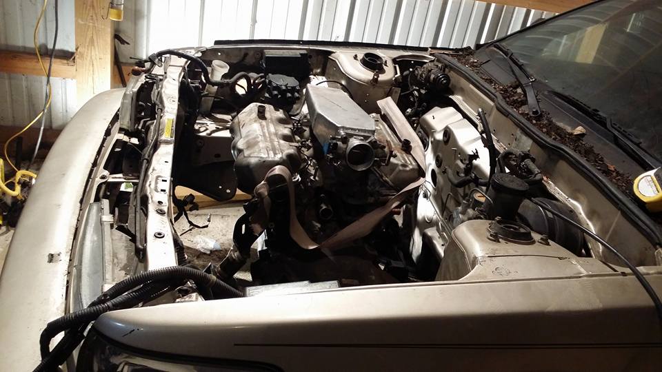
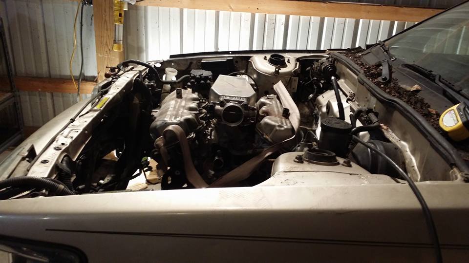
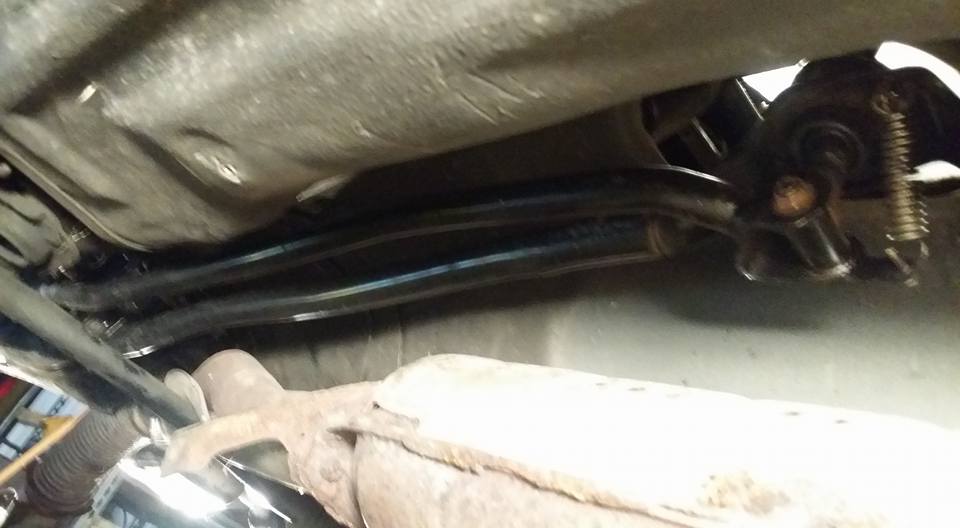
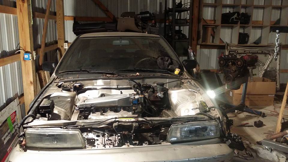
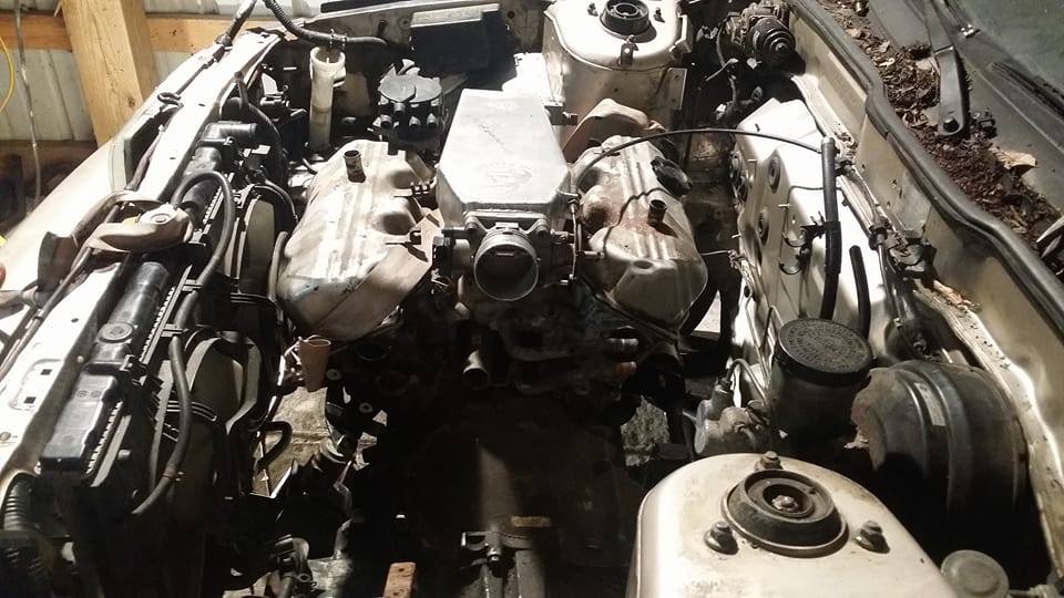
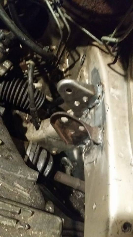
after reinstalling and then adding some washers to the front mount this is essentially where the engine will be all said and done, its actually basically level in relation to the crossmember which should hopefully mean its level in relation to the car. plenty of room for the radiator now. i was also looking at where i can put an intercooler in the front but im debating on going unintercooled for a while to save space and for ease of installation.
one thing i noticed a lot of maximas have that stanzas often dont (besides vg30s) is hood struts.
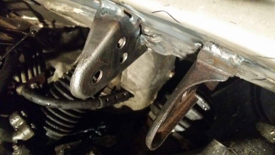
since i deleted my power steering i dont need the bracket for the reservior anymore and since that general area is where the maxima hood strut goes, thats where im going to put mine. i literally used scrap pieces that were in arms reach to make this part, im not even sure its going to actually work out the way i want it so this is mainly just a proof of concept. keeping with the theme of this build, it has all the potential to work and none of it to look good lol
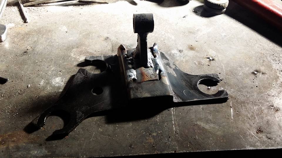
i also just happened to have a bunch of hatch struts laying around from 280s and z31s that i collect when i can for stuff like this because i cant stand hood props. hopefully this crap i slapped together works better than my hood prop otherwise its going in the scrap bin.
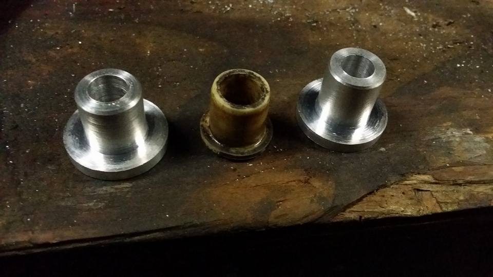
i also noticed there was only one bushing in my shift knuckle thingy thats in the transmission. one of the goals of this build was to totally rebuild the shifter and without that other bushing the shifter has an asston of play so i just turned two new ones out of aluminum with much tighter tolerances so if theres any slop in the shifter its not going to be from these.
after reinstalling and then adding some washers to the front mount this is essentially where the engine will be all said and done, its actually basically level in relation to the crossmember which should hopefully mean its level in relation to the car. plenty of room for the radiator now. i was also looking at where i can put an intercooler in the front but im debating on going unintercooled for a while to save space and for ease of installation.
one thing i noticed a lot of maximas have that stanzas often dont (besides vg30s) is hood struts.
since i deleted my power steering i dont need the bracket for the reservior anymore and since that general area is where the maxima hood strut goes, thats where im going to put mine. i literally used scrap pieces that were in arms reach to make this part, im not even sure its going to actually work out the way i want it so this is mainly just a proof of concept. keeping with the theme of this build, it has all the potential to work and none of it to look good lol
i also just happened to have a bunch of hatch struts laying around from 280s and z31s that i collect when i can for stuff like this because i cant stand hood props. hopefully this crap i slapped together works better than my hood prop otherwise its going in the scrap bin.
i also noticed there was only one bushing in my shift knuckle thingy thats in the transmission. one of the goals of this build was to totally rebuild the shifter and without that other bushing the shifter has an asston of play so i just turned two new ones out of aluminum with much tighter tolerances so if theres any slop in the shifter its not going to be from these.
Last edited by Nate Boslet; 05-18-2018 at 10:00 AM.
 03-08-2017, 12:51 AM
#82
Member
Thread Starter
Join Date: Oct 2016
Posts: 284
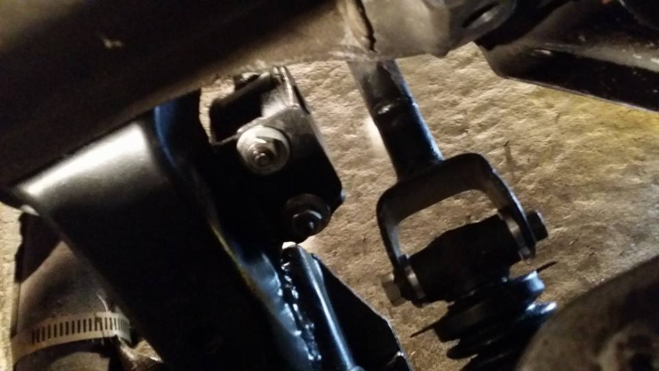
the shift linkages are finished. everything is in and working exactly the way i want. stoked.
heres a video:
https://www.youtube.com/watch?v=ZymW...ature=youtu.be
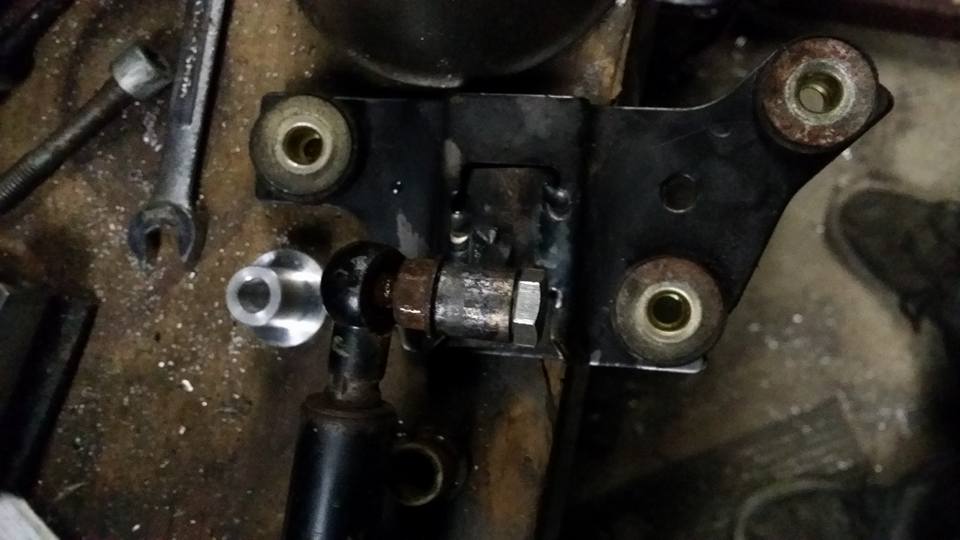
heres the linkages in the car where hopefully they will stay forever.
i had to bend open the one end of the linkages to fit over the new bushings and stuff since i originally took a measurement on the actual knuckle with only one bushing in it so the measurement was about 1/4 inch off.
i think this **** might be from a sentra which is what i got all of my 5 speed swap stuff from when i had the KA in the car. if it wasnt ready for the trash can i might run it to keep the interior looking as stock as possible but i have a better one...
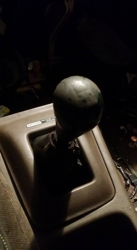
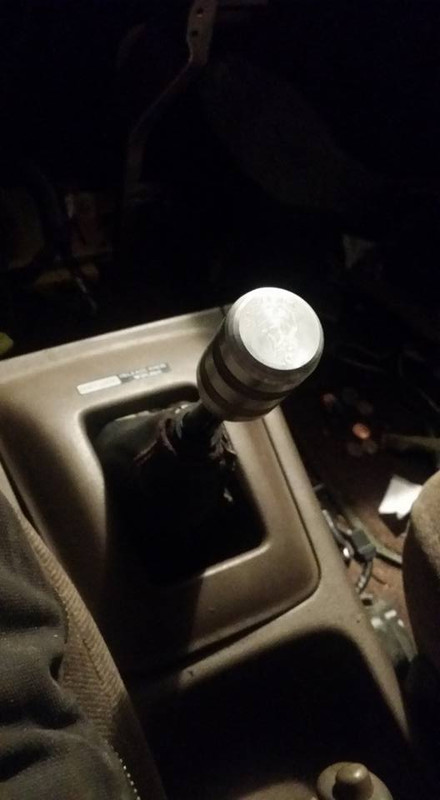
...and it has my logo on it....
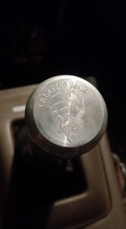
billet aluminum i assume the threads for maxima shift ***** are the same as the sentra and z31 so if anyone is interested in buying one of these ***** off of me hmu on here or on facebook, just search for created sick.
i have decided i am going to prep and paint my engine bay once i pull everything back out to finish gasketting the engine and trans. im going to be painting my valve and timing covers as well so suggestions or examples are welcome. if you think im going to paint this bay with the same half assed indolence that i have assembled this pile of garbage with so far then i just got 2 words for you buddy...... youre right.
P.S. the hood strut thing didnt really work out, im probably going to try to track down some oem stuff instead or get a different strut, the ones i have are too short. im definitely going to get something to work at some point but i realized i should probably focus on other things for now lol
heres a video:
https://www.youtube.com/watch?v=ZymW...ature=youtu.be
heres the linkages in the car where hopefully they will stay forever.
i had to bend open the one end of the linkages to fit over the new bushings and stuff since i originally took a measurement on the actual knuckle with only one bushing in it so the measurement was about 1/4 inch off.
i think this **** might be from a sentra which is what i got all of my 5 speed swap stuff from when i had the KA in the car. if it wasnt ready for the trash can i might run it to keep the interior looking as stock as possible but i have a better one...
...and it has my logo on it....
billet aluminum
i assume the threads for maxima shift ***** are the same as the sentra and z31 so if anyone is interested in buying one of these ***** off of me hmu on here or on facebook, just search for created sick. i have decided i am going to prep and paint my engine bay once i pull everything back out to finish gasketting the engine and trans. im going to be painting my valve and timing covers as well so suggestions or examples are welcome. if you think im going to paint this bay with the same half assed indolence that i have assembled this pile of garbage with so far then i just got 2 words for you buddy...... youre right.
P.S. the hood strut thing didnt really work out, im probably going to try to track down some oem stuff instead or get a different strut, the ones i have are too short. im definitely going to get something to work at some point but i realized i should probably focus on other things for now lol
Last edited by Nate Boslet; 05-18-2018 at 10:01 AM.
03-10-2017, 10:59 AM
#83
Member
Thread Starter
Join Date: Oct 2016
Posts: 284
i realized after fitting up the aluminum alternator bracket that i wouldnt be able to use it because it moves the alternator forward about an inch so i would have to use the z31 cast iron one instead. this bracket is super heavy and the ac bracket part of it kinda stuck out into the radiator area of the bay so i decided to chop it in half.
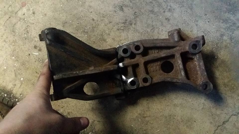
this took me at least an hour and a half of continuous cutting. cast iron sucks and i hope i dont have to work with it ever again after im done with this build lol
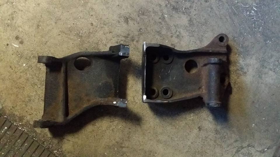
but now that its cut up its much lighter and takes up a lot less room, i may trim it a little further but for now im happy with it.
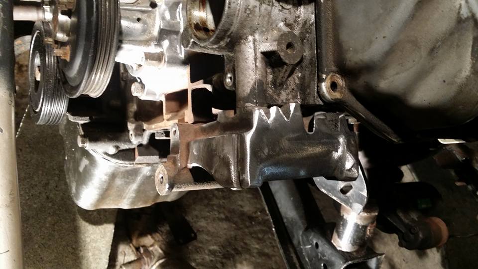
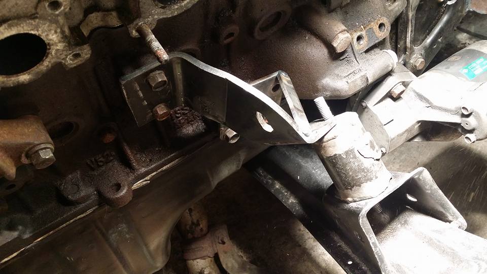
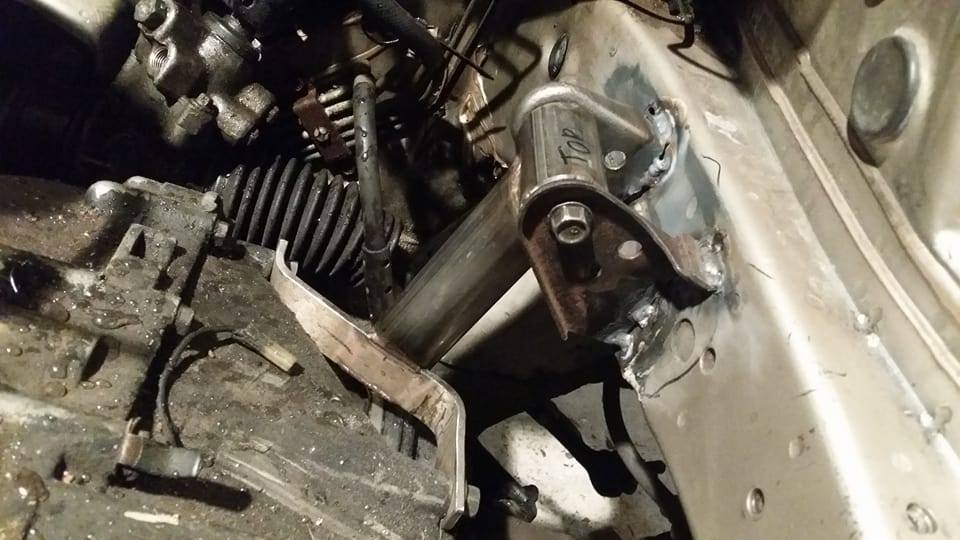
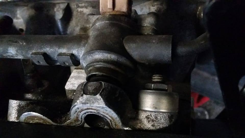
my front mounting bracket needed a little bracing, i used the two bolt holes lower down toward the rear of the block, on the z31 they are for a bracket that bolts to the block and the transmission for bracing i guess. im designing a motor mount/isolator now that will replace the solid mount so i keep the engine noise in the cab to a minimum.
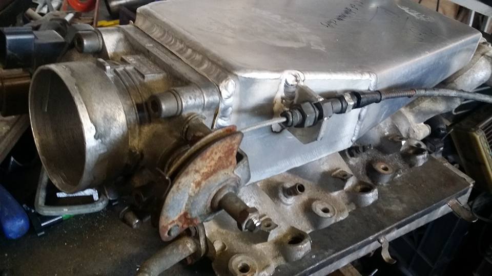
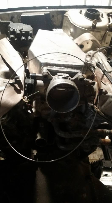
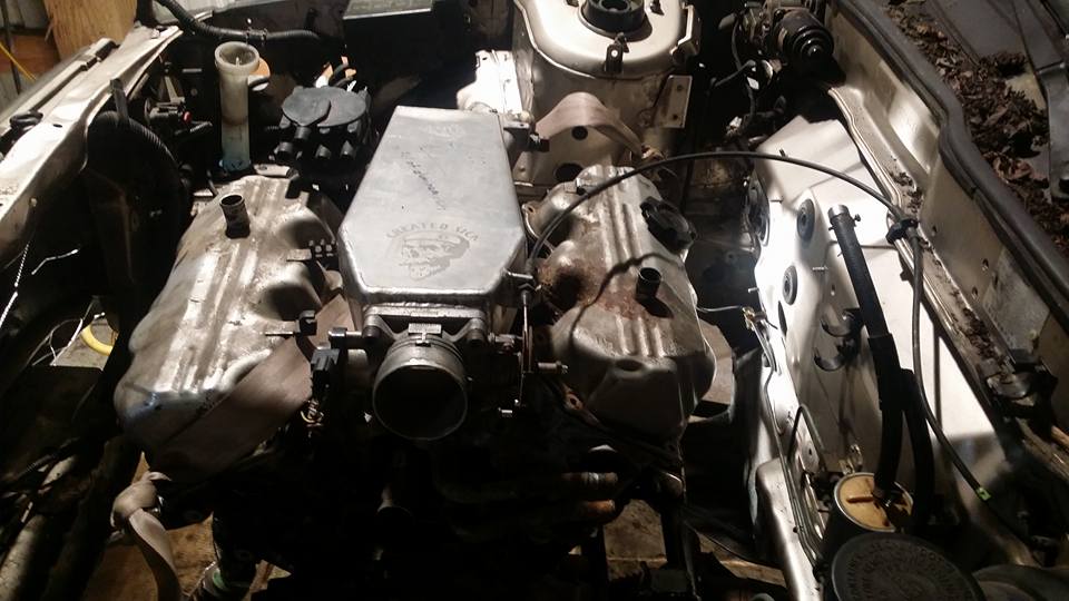
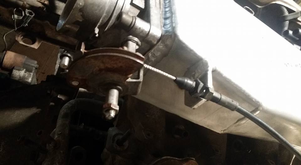
i took the intake home to add the throttle cable bracket.

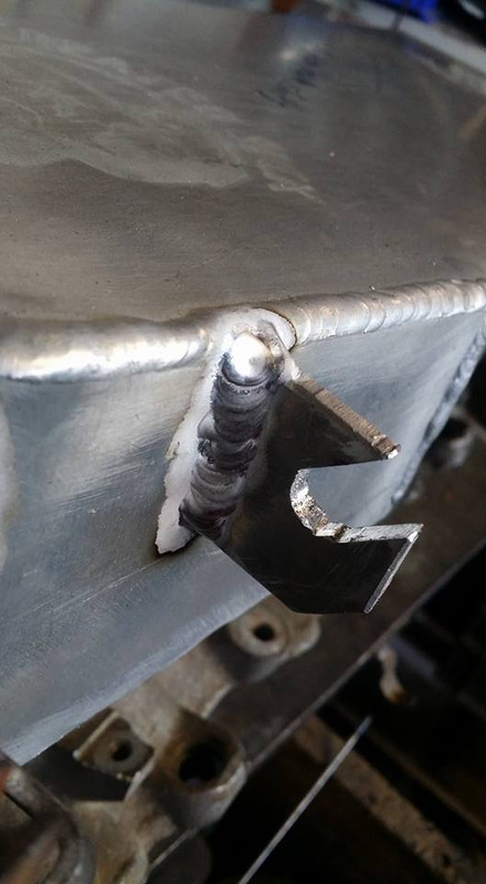
ok idk how many people need to do throttle cables but if you ever do, this little jig is the only way i would ever even consider doing it.
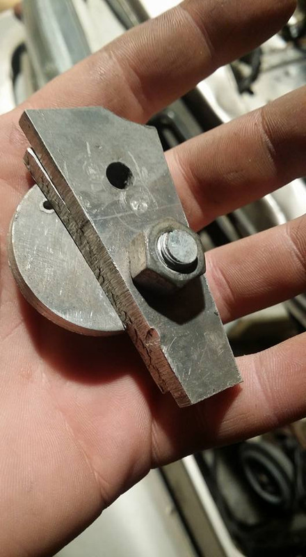
i made it out of scraps obviously. i will probably make a new one with locating pins and a better way to separate the two sides since that can be a pain but for demonstration purposes this will work just fine.
i think the stanzas throttle cable wrapped around the entire engine or something because its literally 10 feet long and i have no idea why, thats fine because too long is better than too short. first thing you want to do is measure where you need to place your barrel, hook up the cable where it will be and pull all the slack out of the cable and then make a mark where the cable lines up with the barrel hole on your throttle.
cut the cable to length. if its your first time doing this i suggest adjusting the throttle nuts so they are in the center of the threaded section of the throttle cable bracket so you have room to adjust if you **** it up.
next you want to fray the end of the cable just a little bit so the frayed points will stick out into the sides of the barrel and provide extra strength, if you dont do this the barrel *WILL* pull right off of the cable. then insert the cable into the jig and clamp the two halves around it.
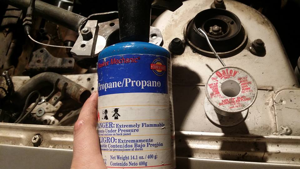
i use a propane torch and silver solder, this stuff is used for plumbing like doing copper pipes and stuff in your house (which is the main reason why i have it and almost used all of the silver solder lol i dont make that many throttle cables) i shouldnt have to say this but i know i do.. BE SAFE. have a fire extinguisher near by and move anything excessively flammable out of your workspace. basically dont be an idiot. this isnt the most dangerous procedure at all but it can become a deadly one if you are stupid enough.
next you want to heat up the jig. JUST the JIG. you dont want to heat the **** out of the cable because it will become brittle. try to aim the torch at the side or bottom of the jig so that no flames are actually touching the cable. next to fraying the cable the next most important thing is to make sure the jig is hot enough, you do not need to melt the aluminum, just get it hot enough to easily melt the solder. you can test this by touching the solder to the top of the jig, if it melts quickly and stays runny, its probably good.
the next most important part is making sure you jam the solder into the bottom of the jig first so that it fills the mold completely without leaving any voids. your main goal here is to leave as solid of a chunk of solder in the mold with as much strands of metal reinforcing the joint as possible.

dont be afraid to waste a bunch of solder, its just solder, jam a whole bunch in there until its running out of the top just to make sure there are no voids. once its full skim the top as best you can without pulling any solder from the mold. you do not want to have to add solder once you have already filled the mold, it cools extremely fast and builds a layer of oxide so if you mess this part up you may as well pull the mold apart, melt everything out of it, clean everything up and start over cause its not gonna work. DO NOT QUENCH. let it air cool and solidify on its own, this is gonna take a while so try to keep an eye on it but maybe find something else to do with yourself while you wait. you want to at least be able to touch the jig before you try to pull it apart.
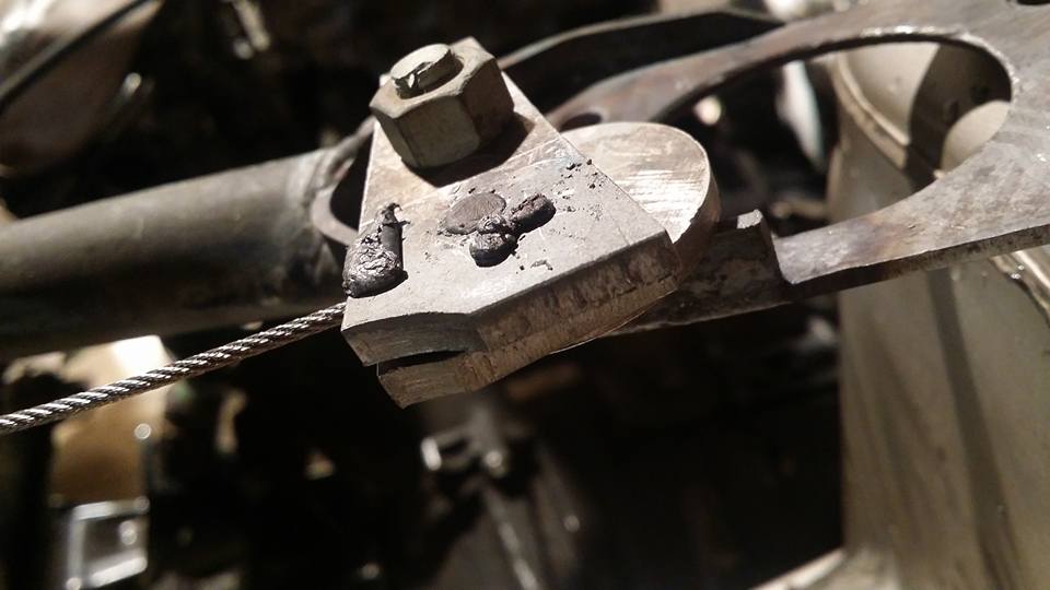
next is the hardest part, pulling the mold apart without destroying the barrel. you essentially plug brazed the two aluminum plates together (if you used some other material this part might be easier but aluminum holds onto heat much better than anything else i had lying around so i personally would just use aluminum.) TAKE YOUR TIME. any careless prying or twisting is gonna snap this thing in half, the amount of force it will see on your car is never going to be anything near what youre going to put it through here so if it lives it should be fine. this part of the process is why i said earlier i want to make a new jig with pins and a better method of separation because when you cant apply force axially to the barrel easily it makes this part really not fun.
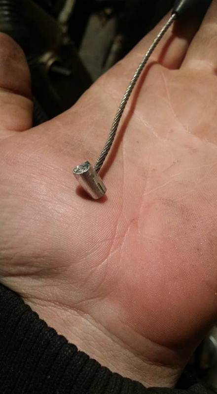
so after its out of the jig, if your jig is anything like mine its slightly oversized to compensate for shirinkage but sometimes the solder doesnt shrink in diameter so you have to do some filing. NBD, you sit there with a file for a little bit and keep filing until the thing fits. once it does fit you can install everything and check to see how well you did.
hopefully you got it right the second time (the first one i made broke in half, i trimmed some strands off and then it was good) i now have a custom throttle cable that isnt 10 feet long and operates pretty much exactly as it would on a stock car, the pedal feels absolutely perfect, the stops are maybe 1/8th inch of pedal from open and closed which is probably tighter than stock... anyway good luck if you ever need to do this.
next im going to be working on my harness and the rear transmission mount, i realized my transmission is sagging and that threw off the shift linkage AGAIN so im hanging that up until the motor is 100% solid. i realized the harness i have is from a 94, ive been having trouble finding an FSM to help me with deleting the stuff i wont need like all the automatic trans stuff and some other things here and there i wont be using. i did find an fsm for a 94 maxima but it only covers the vg30DE not the single cam so if anyone has an fsm and can post the diagrams im looking for that would be awesome and help me out a lot.
this took me at least an hour and a half of continuous cutting. cast iron sucks and i hope i dont have to work with it ever again after im done with this build lol
but now that its cut up its much lighter and takes up a lot less room, i may trim it a little further but for now im happy with it.
my front mounting bracket needed a little bracing, i used the two bolt holes lower down toward the rear of the block, on the z31 they are for a bracket that bolts to the block and the transmission for bracing i guess. im designing a motor mount/isolator now that will replace the solid mount so i keep the engine noise in the cab to a minimum.
i took the intake home to add the throttle cable bracket.
ok idk how many people need to do throttle cables but if you ever do, this little jig is the only way i would ever even consider doing it.
i made it out of scraps obviously. i will probably make a new one with locating pins and a better way to separate the two sides since that can be a pain but for demonstration purposes this will work just fine.
i think the stanzas throttle cable wrapped around the entire engine or something because its literally 10 feet long and i have no idea why, thats fine because too long is better than too short. first thing you want to do is measure where you need to place your barrel, hook up the cable where it will be and pull all the slack out of the cable and then make a mark where the cable lines up with the barrel hole on your throttle.
cut the cable to length. if its your first time doing this i suggest adjusting the throttle nuts so they are in the center of the threaded section of the throttle cable bracket so you have room to adjust if you **** it up.
next you want to fray the end of the cable just a little bit so the frayed points will stick out into the sides of the barrel and provide extra strength, if you dont do this the barrel *WILL* pull right off of the cable. then insert the cable into the jig and clamp the two halves around it.
i use a propane torch and silver solder, this stuff is used for plumbing like doing copper pipes and stuff in your house (which is the main reason why i have it and almost used all of the silver solder lol i dont make that many throttle cables) i shouldnt have to say this but i know i do.. BE SAFE. have a fire extinguisher near by and move anything excessively flammable out of your workspace. basically dont be an idiot. this isnt the most dangerous procedure at all but it can become a deadly one if you are stupid enough.
next you want to heat up the jig. JUST the JIG. you dont want to heat the **** out of the cable because it will become brittle. try to aim the torch at the side or bottom of the jig so that no flames are actually touching the cable. next to fraying the cable the next most important thing is to make sure the jig is hot enough, you do not need to melt the aluminum, just get it hot enough to easily melt the solder. you can test this by touching the solder to the top of the jig, if it melts quickly and stays runny, its probably good.
the next most important part is making sure you jam the solder into the bottom of the jig first so that it fills the mold completely without leaving any voids. your main goal here is to leave as solid of a chunk of solder in the mold with as much strands of metal reinforcing the joint as possible.
dont be afraid to waste a bunch of solder, its just solder, jam a whole bunch in there until its running out of the top just to make sure there are no voids. once its full skim the top as best you can without pulling any solder from the mold. you do not want to have to add solder once you have already filled the mold, it cools extremely fast and builds a layer of oxide so if you mess this part up you may as well pull the mold apart, melt everything out of it, clean everything up and start over cause its not gonna work. DO NOT QUENCH. let it air cool and solidify on its own, this is gonna take a while so try to keep an eye on it but maybe find something else to do with yourself while you wait. you want to at least be able to touch the jig before you try to pull it apart.
next is the hardest part, pulling the mold apart without destroying the barrel. you essentially plug brazed the two aluminum plates together (if you used some other material this part might be easier but aluminum holds onto heat much better than anything else i had lying around so i personally would just use aluminum.) TAKE YOUR TIME. any careless prying or twisting is gonna snap this thing in half, the amount of force it will see on your car is never going to be anything near what youre going to put it through here so if it lives it should be fine. this part of the process is why i said earlier i want to make a new jig with pins and a better method of separation because when you cant apply force axially to the barrel easily it makes this part really not fun.
so after its out of the jig, if your jig is anything like mine its slightly oversized to compensate for shirinkage but sometimes the solder doesnt shrink in diameter so you have to do some filing. NBD, you sit there with a file for a little bit and keep filing until the thing fits. once it does fit you can install everything and check to see how well you did.
hopefully you got it right the second time (the first one i made broke in half, i trimmed some strands off and then it was good) i now have a custom throttle cable that isnt 10 feet long and operates pretty much exactly as it would on a stock car, the pedal feels absolutely perfect, the stops are maybe 1/8th inch of pedal from open and closed which is probably tighter than stock... anyway good luck if you ever need to do this.
next im going to be working on my harness and the rear transmission mount, i realized my transmission is sagging and that threw off the shift linkage AGAIN so im hanging that up until the motor is 100% solid. i realized the harness i have is from a 94, ive been having trouble finding an FSM to help me with deleting the stuff i wont need like all the automatic trans stuff and some other things here and there i wont be using. i did find an fsm for a 94 maxima but it only covers the vg30DE not the single cam so if anyone has an fsm and can post the diagrams im looking for that would be awesome and help me out a lot.
Last edited by Nate Boslet; 05-18-2018 at 10:02 AM.
03-10-2017, 05:17 PM
#84
Senior Member

Join Date: Apr 2007
Location: Albuquerque, NM
Posts: 1,323
03-11-2017, 01:32 PM
#85
Member
Thread Starter
Join Date: Oct 2016
Posts: 284
03-18-2017, 01:49 PM
#86
Member
Thread Starter
Join Date: Oct 2016
Posts: 284
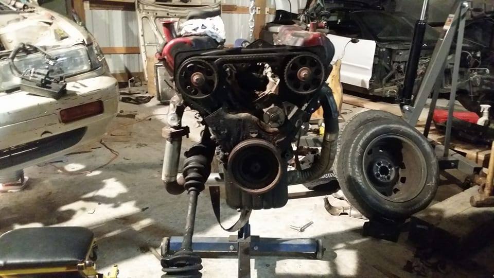
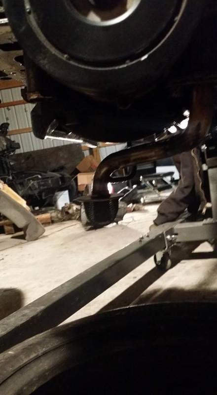
i decided to put the car on the floor to check out the ground clearance and to make sure nothing in the drivetrain is binding.
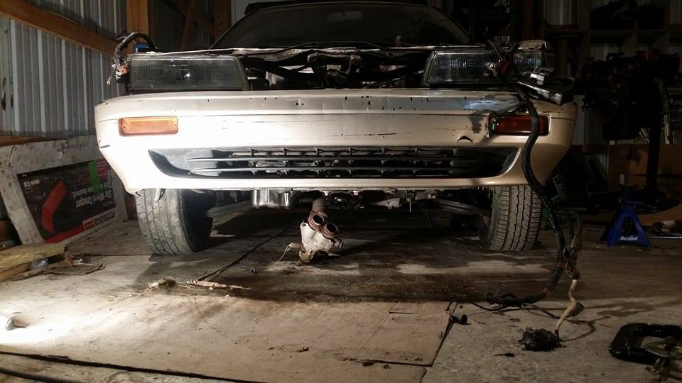
the car rolls around fine and doesnt feel like its having any trouble at all anywhere. the axles spin freely and look like they have plenty of clearance.
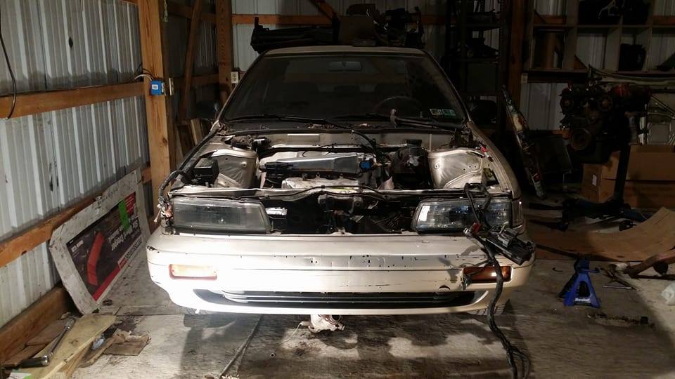
i have the wheel gap of a ****ing pathfinder. im assuming the suspension just needs to settle but ive never seen suspension settle more than an inch so ill probably do coils in the future to address this. im wondering if the VG is that much lighter than the KA that my spring rates are too high now or something.
i tied up the exhaust that im not gonna use just to get an idea of where everything is gonna be at. the oil pan is still a little more vulnerable than i would prefer but like i said i will make a new one or modify this one if i really feel that it will be an issue. without the coils i have like a foot of ground clearance so if i bust an oil pan ill have no one to blame but myself anyway lol
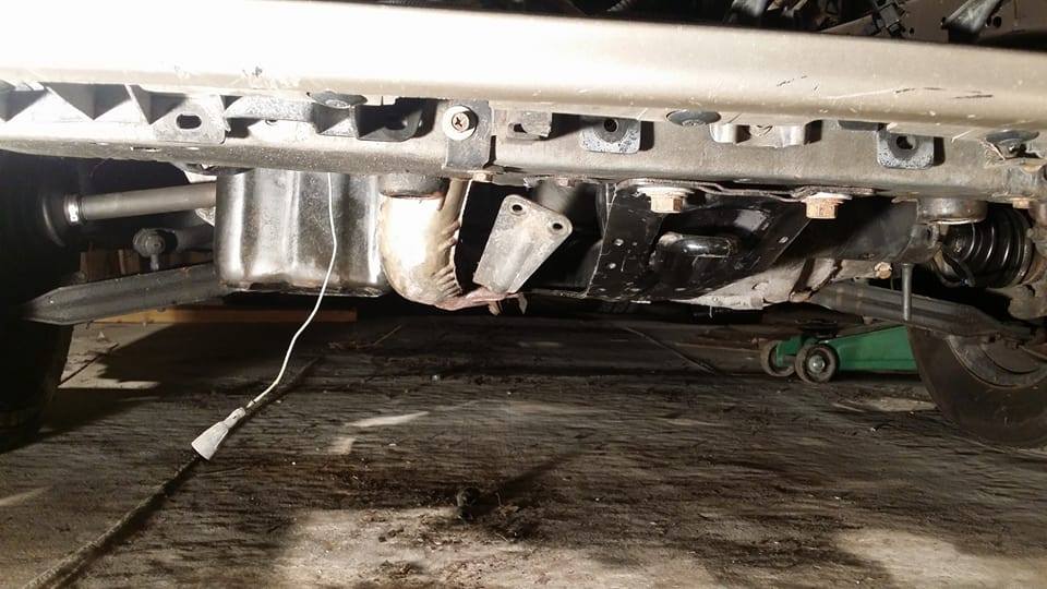
i was looking at potential turbo placements and realized im going to have a really hard time running the exhaust.
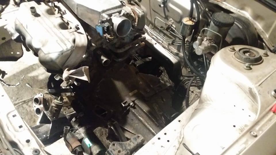
if/when i do go turbo with this car i will have to have the turbo facing the firewall, the intake tubing will have to go directly into the throttle and the exhaust will have to fit very tightly in front of the engine in between the radiator. it would have to be non intercooled and i would probably have to run a MAP setup instead of MAF cause idk where i would put a MAF, i dont want it in front of the turbo because i would want to run a semi large turbo to keep my IAT as low as possible. smaller turbo+more boost= higher IAT larger turbo+lower boost=lower IAT, at least thats what ive read. thinking about just using the HX35 from my z since thats probably going to sit for the next few years anyway.
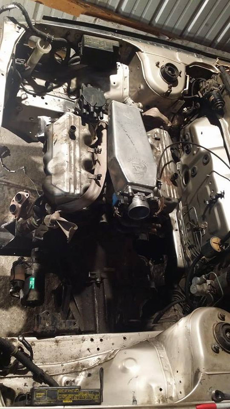
i put the radiator back in and the battery tray and quickly realized that i have basically no room to do anything fancy in here. im basically just going to modify the stock maxima headers and try to run the exhaust NA just to get the car on the road and maybe iron out whatever issues i run into before i go turbo at some point.
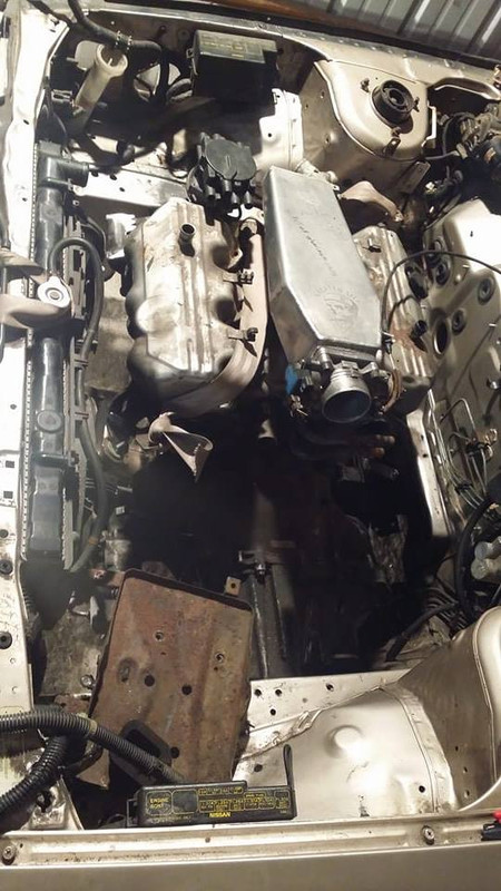
since im going NA at the moment, i have room. things will fit. its tight but i can get everything to work.
i am really spreading my income thin with this project right now, im looking for more work all the time and really not finding much. i still need the rear trans bracket to finish mounting the engine and im not having much luck finding one local so if anyone has one let me know. i really would like to get the car on the road in a month or two i dont really see any reason why i couldnt. i realized that if the car was gonna be turbo that deadline would become more like a year or two with the money i have to work with right now so i think ill live without boost for a while lol
i dont think i pimped my business page before so im gonna right now, if anyone needs anything fabricated, feel free to check out the parts i currently offer or hmu for something custom. fb.me/CreatedSick
the car rolls around fine and doesnt feel like its having any trouble at all anywhere. the axles spin freely and look like they have plenty of clearance.
i have the wheel gap of a ****ing pathfinder. im assuming the suspension just needs to settle but ive never seen suspension settle more than an inch so ill probably do coils in the future to address this. im wondering if the VG is that much lighter than the KA that my spring rates are too high now or something.
i tied up the exhaust that im not gonna use just to get an idea of where everything is gonna be at. the oil pan is still a little more vulnerable than i would prefer but like i said i will make a new one or modify this one if i really feel that it will be an issue. without the coils i have like a foot of ground clearance so if i bust an oil pan ill have no one to blame but myself anyway lol
i was looking at potential turbo placements and realized im going to have a really hard time running the exhaust.
if/when i do go turbo with this car i will have to have the turbo facing the firewall, the intake tubing will have to go directly into the throttle and the exhaust will have to fit very tightly in front of the engine in between the radiator. it would have to be non intercooled and i would probably have to run a MAP setup instead of MAF cause idk where i would put a MAF, i dont want it in front of the turbo because i would want to run a semi large turbo to keep my IAT as low as possible. smaller turbo+more boost= higher IAT larger turbo+lower boost=lower IAT, at least thats what ive read. thinking about just using the HX35 from my z since thats probably going to sit for the next few years anyway.
i put the radiator back in and the battery tray and quickly realized that i have basically no room to do anything fancy in here. im basically just going to modify the stock maxima headers and try to run the exhaust NA just to get the car on the road and maybe iron out whatever issues i run into before i go turbo at some point.
since im going NA at the moment, i have room. things will fit. its tight but i can get everything to work.
i am really spreading my income thin with this project right now, im looking for more work all the time and really not finding much. i still need the rear trans bracket to finish mounting the engine and im not having much luck finding one local so if anyone has one let me know. i really would like to get the car on the road in a month or two i dont really see any reason why i couldnt. i realized that if the car was gonna be turbo that deadline would become more like a year or two with the money i have to work with right now so i think ill live without boost for a while lol
i dont think i pimped my business page before so im gonna right now, if anyone needs anything fabricated, feel free to check out the parts i currently offer or hmu for something custom. fb.me/CreatedSick
Last edited by Nate Boslet; 05-18-2018 at 10:11 AM.
03-26-2017, 10:29 PM
#87
Member
Thread Starter
Join Date: Oct 2016
Posts: 284
MASSIVE TRANS MOUNT DEDICATED UPDATE
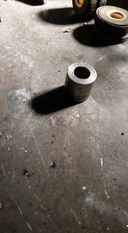
this is what i had to work with as far as mounting to the trans. not much...
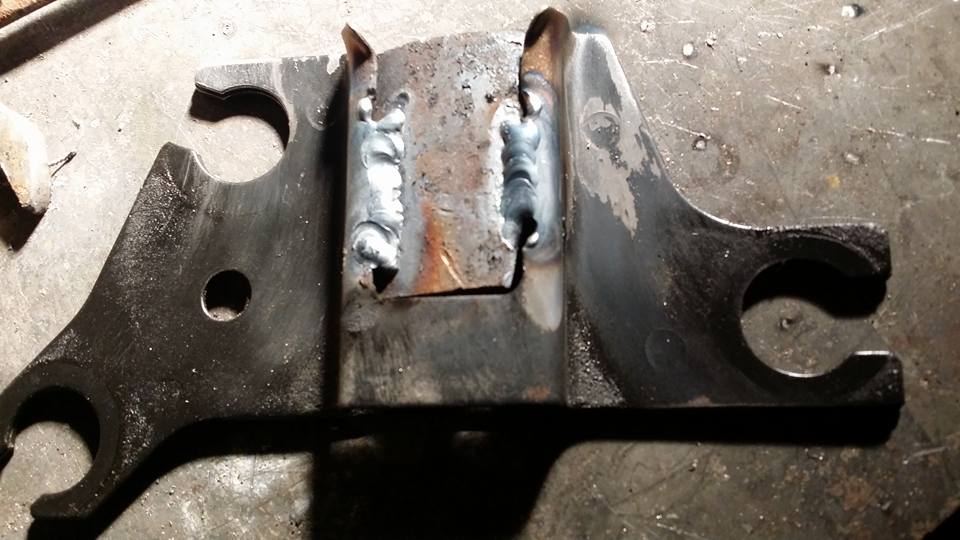
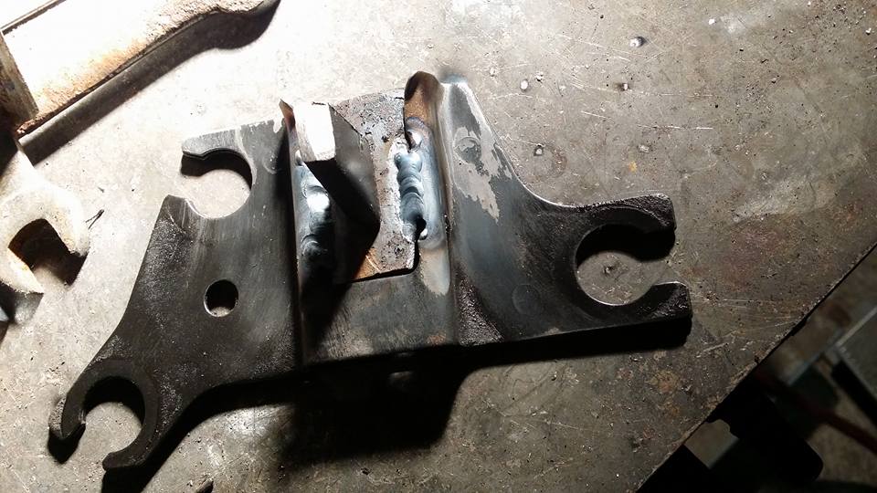
first i made a bracket that would reach at least two bolt holes, i figured if i used reasonably thick material it would be strong enough to withstand the compressive force the transmission will be putting on it under load. i used two bolts to measure the distance between the two holes on one axis and then the distance from them front to back with a straight edge. once i had the measurements i went home and made a simple jig and bent the plate to fit it.
i took this as an opportunity to practice notching, something i will probably be doing a lot more of in the future when i start building roll cages. i didnt use a tube notching machine or any specific tool like that at all, if anyone is interested in the method i used this video explains it really well :
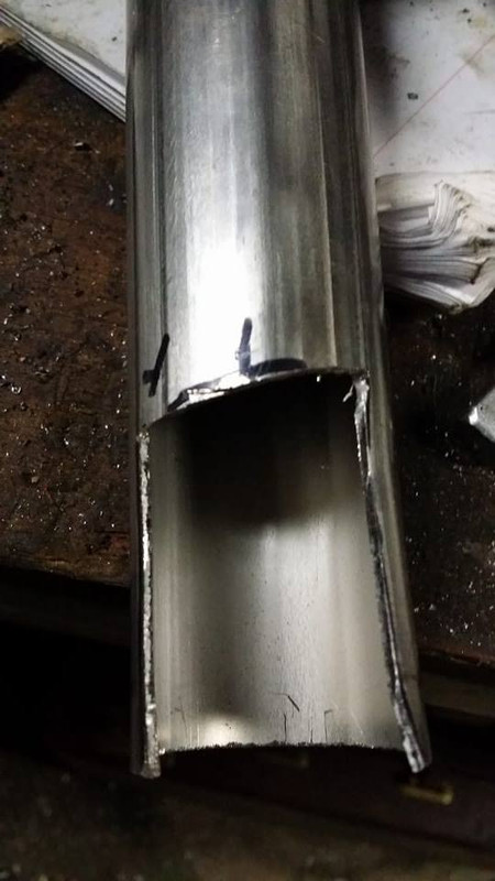
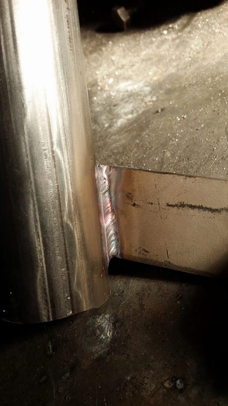
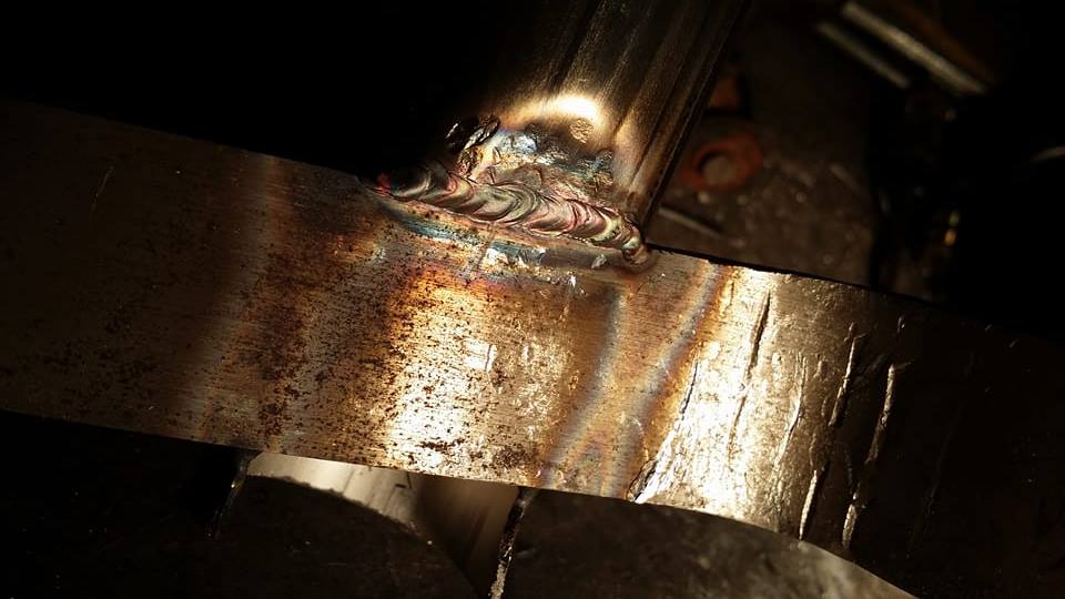
after taking some more measurements and making some marks on the tubing, i notched out a section of the tube that was about the thickness of the plate.
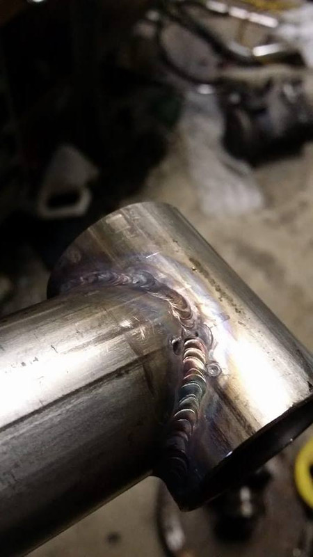
then i welded the tube to the plate. seemed like the logical thing to do.
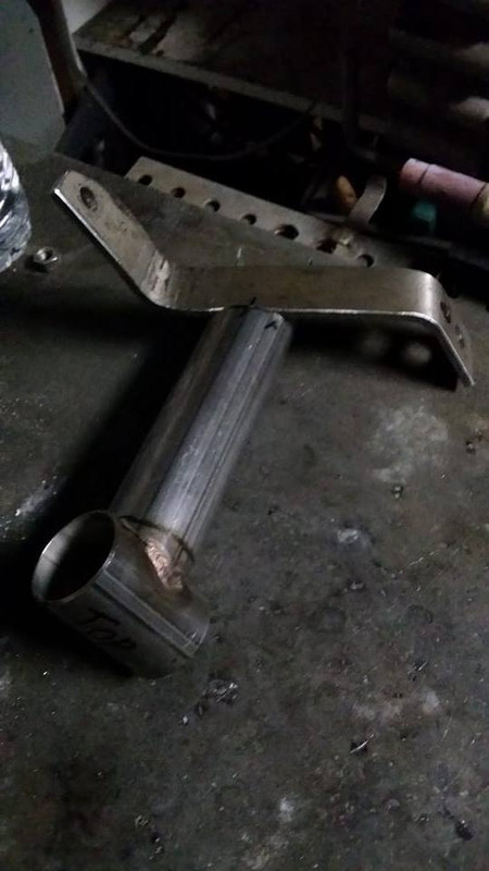

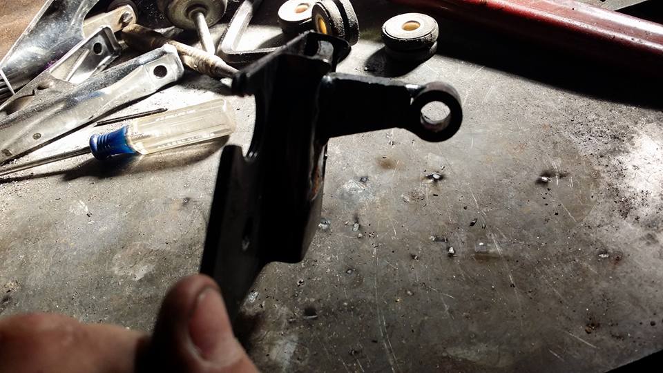
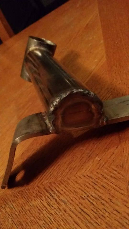
i trimmed off the excess and capped the bottom. here is the (mostly) finished product.

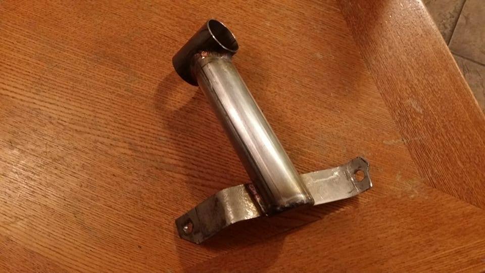
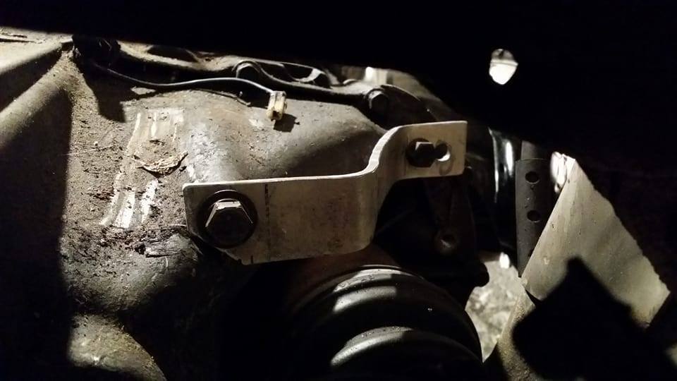
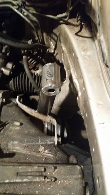
i plan to fill the upper tube with window weld and suspend a pin in it for the bolt to go through so this mount is isolated but that stuff takes a while to cure and i wanted to bang out this mount so i tacked some washers to locate the bolt in the center of the tube then i bolted it up to the trans to see where it lined up with the frame.
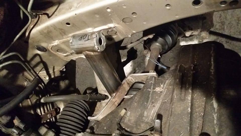
it actually isnt too far off from stock from the looks of it but the mounting bracket pokes out a little further. i took some measurements of the distance from the frame and cut the fins off the stock mount to length.
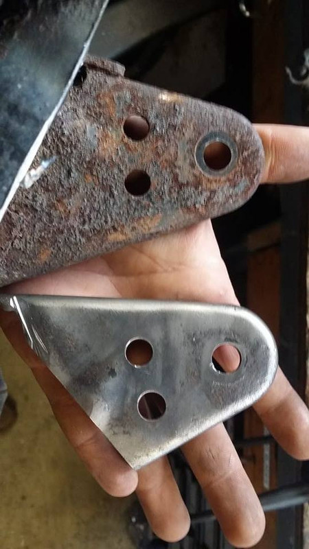
the bracket was rusted to **** but cleaned up surprisingly well. after paint idk if youll be able to tell they were ever rusty.
after prepping the frame (poorly) i tacked the fins in place.
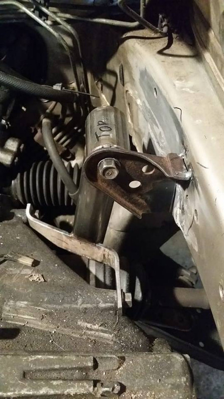
after getting them tacked up i chain welded them and did my best to not catch whatever junk is inside my frame rails on fire.
considering the wall thickness of my frame rail and these brackets i dont see any real reason to fully weld them to the car. a chain weld should hold just fine considering the forces and the fact that they will only be lengthwise means if i brake these off i must have been making way more power than i expected to and also dead hooked (i doubt this car will ever see slicks so im not worried...)
i threw the bolt in, lowered the jack and the engine and transmission are finally mounted. done. i do not plan to move or change anything else if i dont have to. i am going to work with what little space i have and be happy i dont have to ****ing do any of this ever again.
next is the exhaust. the tig welder is still at the garage so hopefully i can bang that out in a day or two, really shouldnt take much with the other motor sitting right there on the stand but we will see how much i need to cut up and weld, could potentially be a whole bunch of that. i have the shift linkage chopped in half bolted to the car so im gonna try to get that tacked up and finished so i know its exactly where i want it and then i can move onto wiring and fuel.
this is what i had to work with as far as mounting to the trans. not much...
first i made a bracket that would reach at least two bolt holes, i figured if i used reasonably thick material it would be strong enough to withstand the compressive force the transmission will be putting on it under load. i used two bolts to measure the distance between the two holes on one axis and then the distance from them front to back with a straight edge. once i had the measurements i went home and made a simple jig and bent the plate to fit it.
i took this as an opportunity to practice notching, something i will probably be doing a lot more of in the future when i start building roll cages. i didnt use a tube notching machine or any specific tool like that at all, if anyone is interested in the method i used this video explains it really well :
after taking some more measurements and making some marks on the tubing, i notched out a section of the tube that was about the thickness of the plate.
then i welded the tube to the plate. seemed like the logical thing to do.
i trimmed off the excess and capped the bottom. here is the (mostly) finished product.
i plan to fill the upper tube with window weld and suspend a pin in it for the bolt to go through so this mount is isolated but that stuff takes a while to cure and i wanted to bang out this mount so i tacked some washers to locate the bolt in the center of the tube then i bolted it up to the trans to see where it lined up with the frame.
it actually isnt too far off from stock from the looks of it but the mounting bracket pokes out a little further. i took some measurements of the distance from the frame and cut the fins off the stock mount to length.
the bracket was rusted to **** but cleaned up surprisingly well. after paint idk if youll be able to tell they were ever rusty.
after prepping the frame (poorly) i tacked the fins in place.
after getting them tacked up i chain welded them and did my best to not catch whatever junk is inside my frame rails on fire.
considering the wall thickness of my frame rail and these brackets i dont see any real reason to fully weld them to the car. a chain weld should hold just fine considering the forces and the fact that they will only be lengthwise means if i brake these off i must have been making way more power than i expected to and also dead hooked (i doubt this car will ever see slicks so im not worried...)
i threw the bolt in, lowered the jack and the engine and transmission are finally mounted. done. i do not plan to move or change anything else if i dont have to. i am going to work with what little space i have and be happy i dont have to ****ing do any of this ever again.
next is the exhaust. the tig welder is still at the garage so hopefully i can bang that out in a day or two, really shouldnt take much with the other motor sitting right there on the stand but we will see how much i need to cut up and weld, could potentially be a whole bunch of that. i have the shift linkage chopped in half bolted to the car so im gonna try to get that tacked up and finished so i know its exactly where i want it and then i can move onto wiring and fuel.
Last edited by Nate Boslet; 05-18-2018 at 10:17 AM.
03-31-2017, 01:26 PM
#88
Member
Thread Starter
Join Date: Oct 2016
Posts: 284
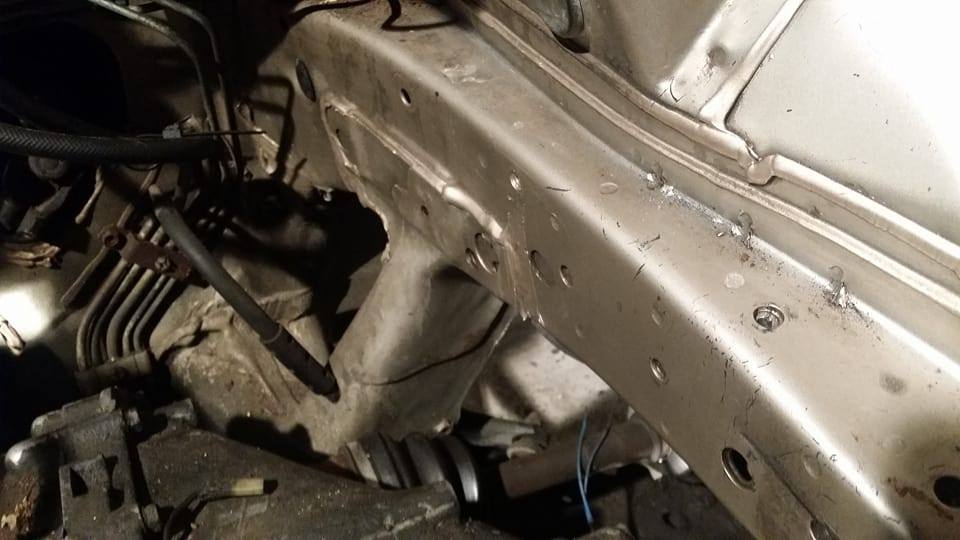
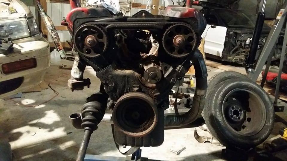
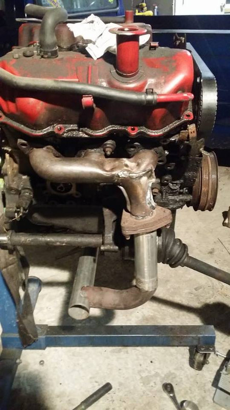
NA headers are essentially done. need to be fully welded up but the layout is done. i managed to make everything with the stock maxima stuff i had and some two inch tubing i had laying around. i didnt put any real effort into making this stuff flow well or look great because i dont want to think twice about throwing it into the trash when i make the turbo stuff.
i started with the front header, i new i would need a flange to connect the headers to the rest of the exhaust behind the engine so i just cut it out of the front header entirely.
you may also notice that the headers are flipped around, i had to do this because my crossmember is where the exhaust should be.
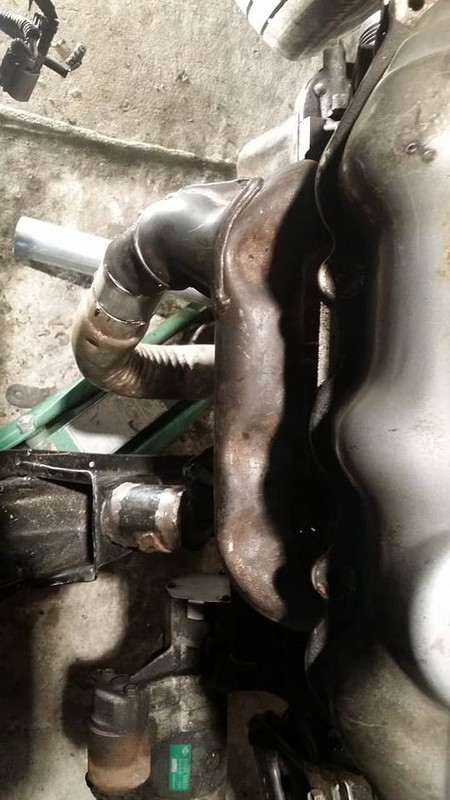
oil pan clearance
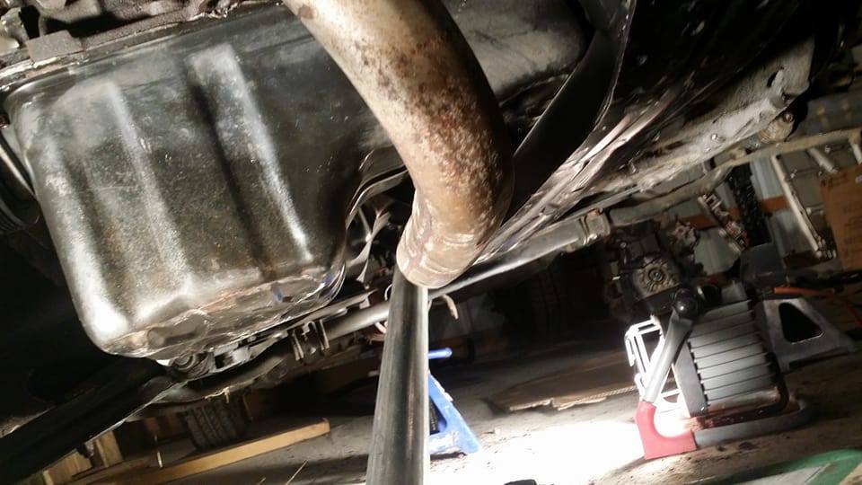
the front headers are extremely close to the radiator fans, i really doubt they will hurt anything since the fans have a heat shield and they arent touching but theres really nothing i can do about it without chopping my tubing and stuff all completely apart and basically pie cutting the tubing so it hugged the engine more but i already did that on my z and i really dont want to put that much effort and time into this exhaust that im basically only making to get the car running.
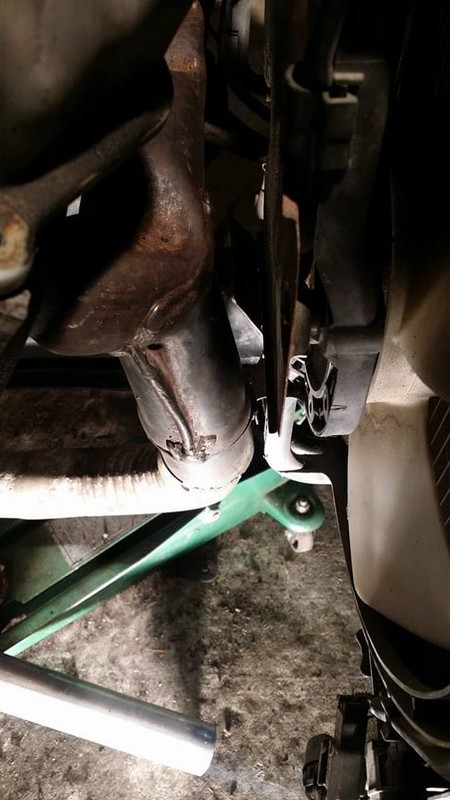
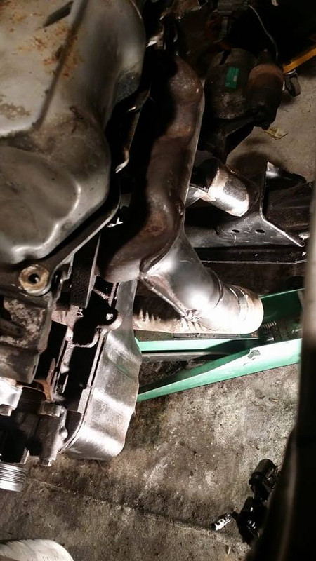
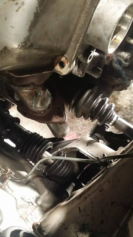
the rear header had to be snaked between the axle and steering rack, no surprise here but theres not much room for anything back there, again, i dont think the heat is going to really destroy anything back there but if i notice it is ill heat wrap the headers and later the turbo downpipe.
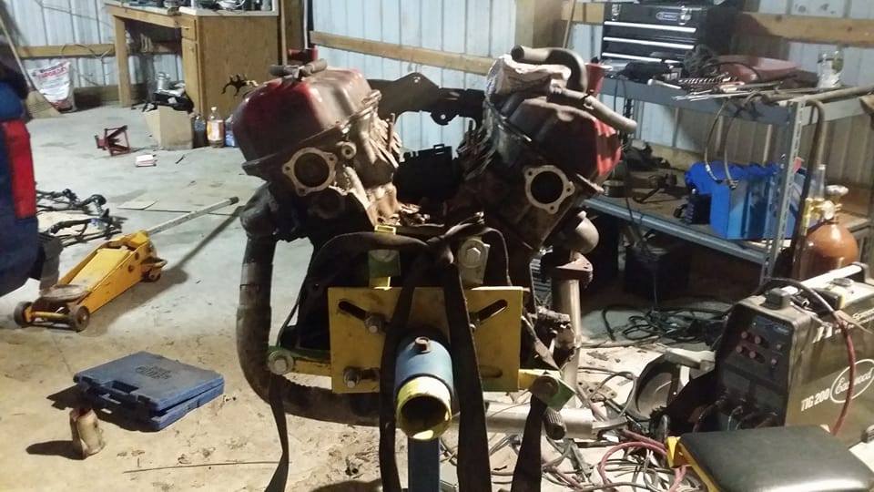
i did basically all of the welding on my spare engine. having this and the spare junk axle helped a lot because i could put the exhaust exactly as far or as close to the axle or steering rack as i wanted. i tried to put it right in between so it hopefully doesnt burn either of them. its nowhere near touching them at all but i have no idea how much this material is going to radiate heat, hopefully not much.
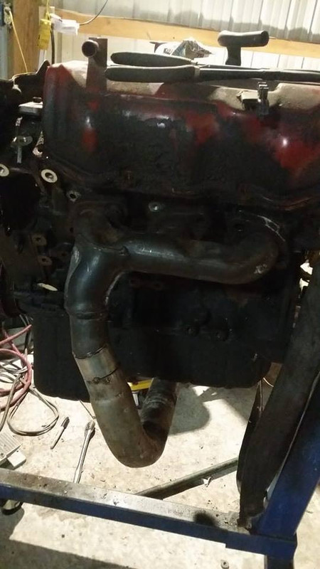
i know what yall are thinkin, and i was kinda worried about it too for a second, without that front flange getting the exhaust on the car is gonna be impossible, how will it fit? well since the front header uses bolts instead of studs, it is actually really easy, probably easier than the stock stuff is. i put the rear header on first, then i just throw the whole front header under the car and kinda jangle it up through the back and then bolt up the front, throw some nuts on the back flange and im done. everything fits up through where it needs to be and the rear flange is right where i want it.
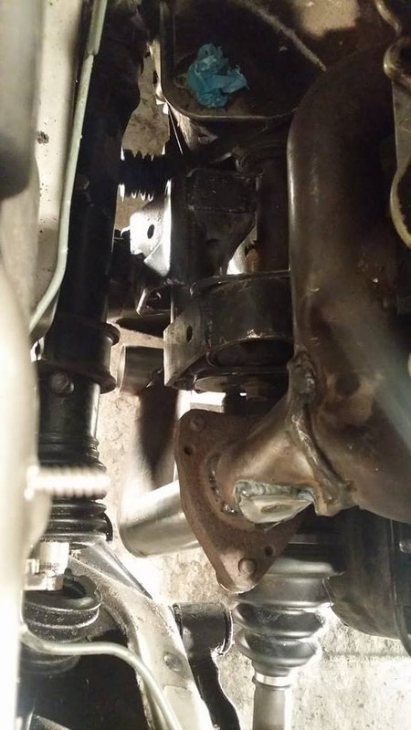
here it is all bolted into the car.
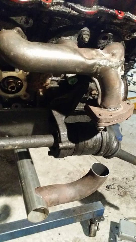
i didnt fully bolt the steering rack into the car, i really just wanted to get an idea of where it would be, when it is actually bolted in it should have about another half inch or so of room so im not really worried about that.
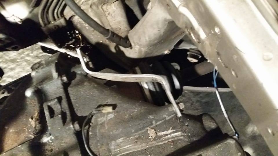
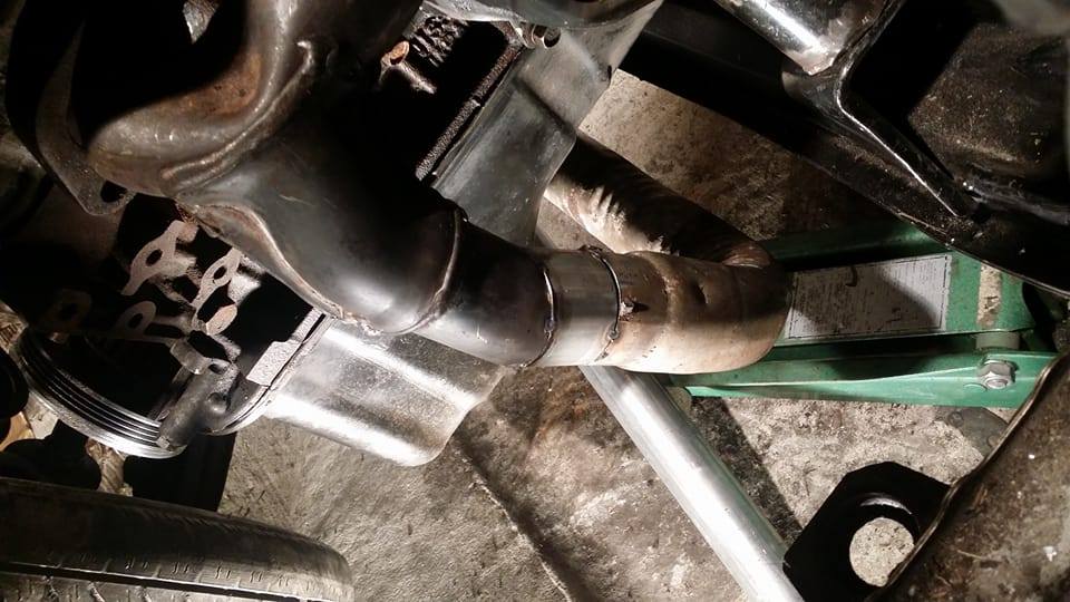
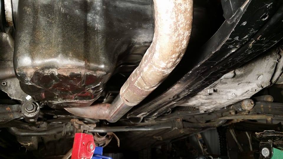
it also looks like this pipe is really close to the subframe but you can see in the pic after this one that its actually like 2 or 3 inches away. really none of the exhaust is anywhere near anything it shouldnt be besides the radiator fans and the axle and steering rack.
another important thing for the exhaust to avoid is the ground, while the exhaust looks like it may be the lowest thing on the car it is still tucked up enough where i dont think it will ever be an issue, even with the coils.
the flange i cut out of the front header is now welded to the end of the tube that will connect the rest of the exhaust to the headers. im going to use the little humped section to get over the sway bar and then the flex pipe behind that so that the rest of the exhaust can swing a little bit. i wont need it further up because the engine is going to have mostly poly mounts so it shouldnt be able to move enough for the flex pipe to really be needed up there, plus there isnt any room for it up front. im gonna probably finish up the exhaust tonight or tomorrow and then ill move on to the harness which is starting to look like it might take a lot less work than i was expecting. we will see.
i started with the front header, i new i would need a flange to connect the headers to the rest of the exhaust behind the engine so i just cut it out of the front header entirely.
you may also notice that the headers are flipped around, i had to do this because my crossmember is where the exhaust should be.
oil pan clearance
the front headers are extremely close to the radiator fans, i really doubt they will hurt anything since the fans have a heat shield and they arent touching but theres really nothing i can do about it without chopping my tubing and stuff all completely apart and basically pie cutting the tubing so it hugged the engine more but i already did that on my z and i really dont want to put that much effort and time into this exhaust that im basically only making to get the car running.
the rear header had to be snaked between the axle and steering rack, no surprise here but theres not much room for anything back there, again, i dont think the heat is going to really destroy anything back there but if i notice it is ill heat wrap the headers and later the turbo downpipe.
i did basically all of the welding on my spare engine. having this and the spare junk axle helped a lot because i could put the exhaust exactly as far or as close to the axle or steering rack as i wanted. i tried to put it right in between so it hopefully doesnt burn either of them. its nowhere near touching them at all but i have no idea how much this material is going to radiate heat, hopefully not much.
i know what yall are thinkin, and i was kinda worried about it too for a second, without that front flange getting the exhaust on the car is gonna be impossible, how will it fit? well since the front header uses bolts instead of studs, it is actually really easy, probably easier than the stock stuff is. i put the rear header on first, then i just throw the whole front header under the car and kinda jangle it up through the back and then bolt up the front, throw some nuts on the back flange and im done. everything fits up through where it needs to be and the rear flange is right where i want it.
here it is all bolted into the car.
i didnt fully bolt the steering rack into the car, i really just wanted to get an idea of where it would be, when it is actually bolted in it should have about another half inch or so of room so im not really worried about that.
it also looks like this pipe is really close to the subframe but you can see in the pic after this one that its actually like 2 or 3 inches away. really none of the exhaust is anywhere near anything it shouldnt be besides the radiator fans and the axle and steering rack.
another important thing for the exhaust to avoid is the ground, while the exhaust looks like it may be the lowest thing on the car it is still tucked up enough where i dont think it will ever be an issue, even with the coils.
the flange i cut out of the front header is now welded to the end of the tube that will connect the rest of the exhaust to the headers. im going to use the little humped section to get over the sway bar and then the flex pipe behind that so that the rest of the exhaust can swing a little bit. i wont need it further up because the engine is going to have mostly poly mounts so it shouldnt be able to move enough for the flex pipe to really be needed up there, plus there isnt any room for it up front. im gonna probably finish up the exhaust tonight or tomorrow and then ill move on to the harness which is starting to look like it might take a lot less work than i was expecting. we will see.
Last edited by Nate Boslet; 05-18-2018 at 10:18 AM.
04-06-2017, 11:36 PM
#89
Member
Thread Starter
Join Date: Oct 2016
Posts: 284
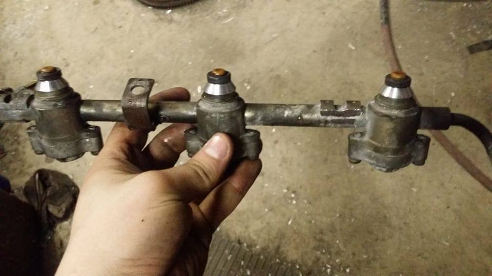
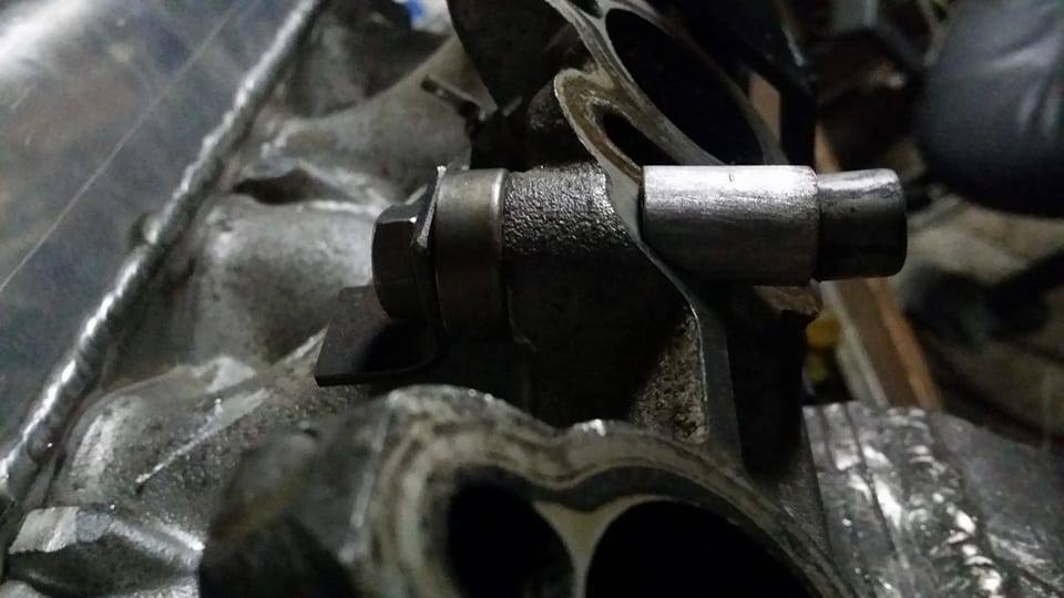
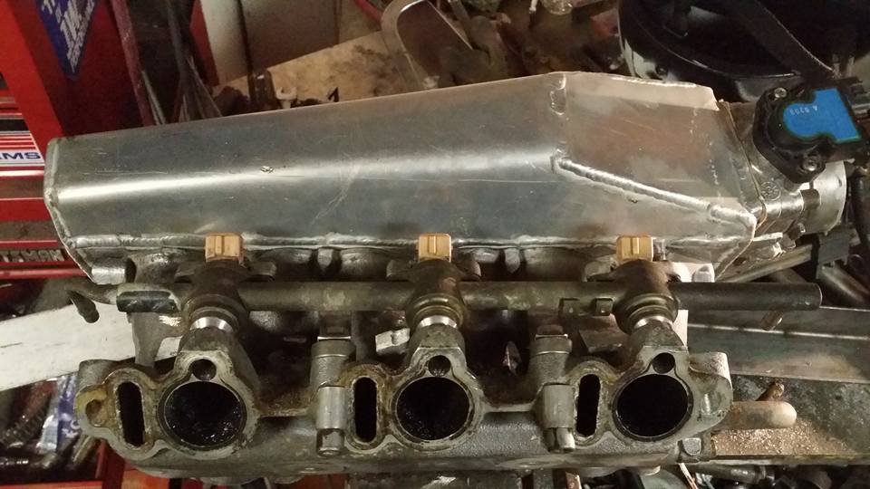
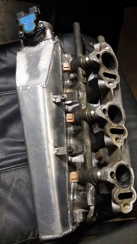
FUEL RAILS. i had to decide pretty much right away whether i was going to run top feed or side feed injectors because of the little tabs that the top feed rails bolt to. i decided it would probably be cheaper and easier to just use the side feed rails i got off of the maxima.
i was able to chop off the outside ones with my sawzall but the middle one needed to be drilled into and then cut two more times at an angle. this wont really be visible on the car so i really didnt care what it looks like.
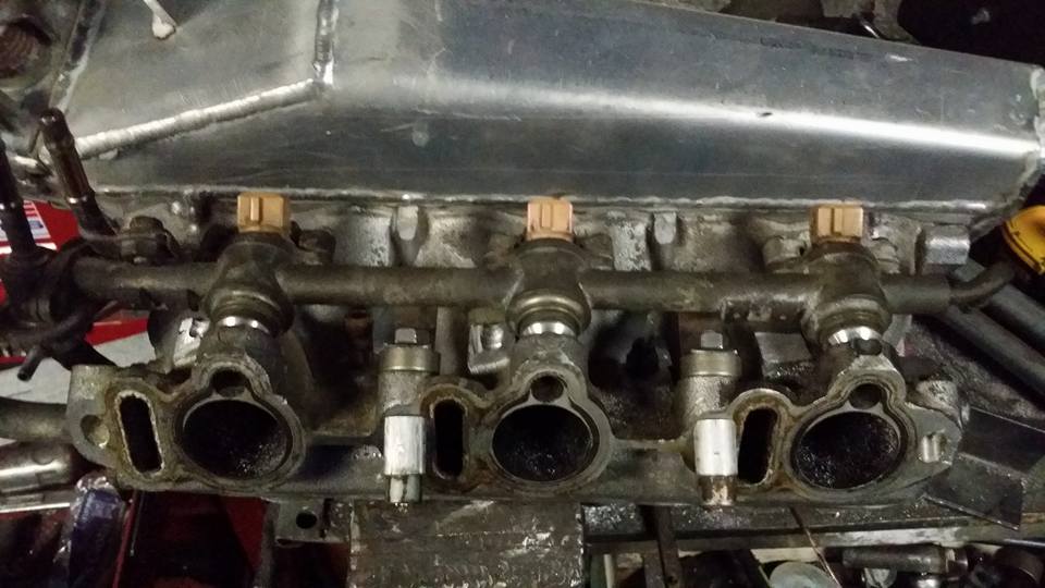
the fuel rails now fit where they will need to go.
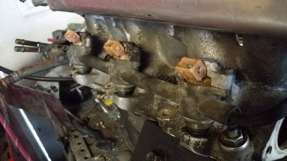
obviously the original mounting tabs had to go. i tried drilling out the spot welds on one of them but it turns out the entire tab is brazed onto the rail AND spot welded so i ripped a hole in one of the rails. i welded it up in a minute or so but the rest of them i just chopped off with the sawzall.
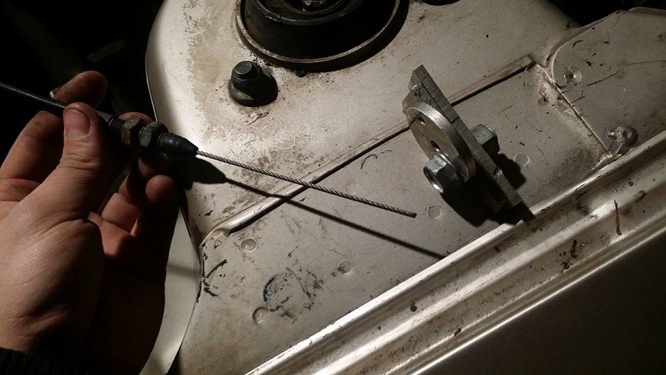
i already knew the studs would be really close but after seeing this i knew the ones on my car would actually hit the rails (these ones are just on a jig i made for locating throttle plates on my intakes) cutting the studs down isnt really a big deal tho.
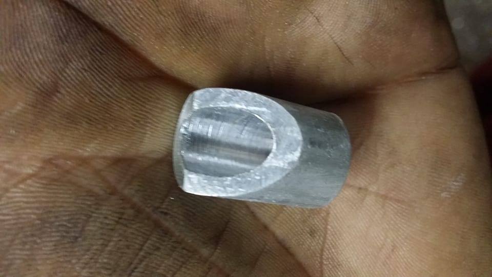
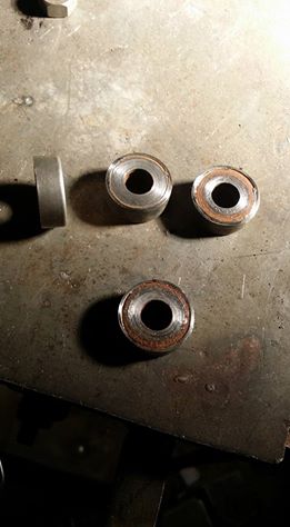
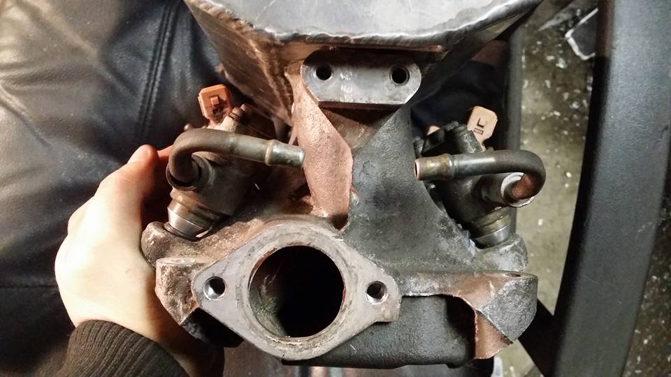
there are several differences between this lower and the maxima lower and the injectors needed to sit a little higher than they would on the maxima. in order to not have to run 2 or 3 injector orings (which would have been a really bad idea) i decided to make up some spacers.
heres one done, 5 more to go.
the cone shape was not for looks, without that extra relief the spacer would have hit the runner. the reason i know this is because the first one i made wasnt cone shaped and it didnt fit lol (pretend the tab isnt there yet, i didnt do everything in the same order im explaining it because my phone was dead for a lot of the work i was doing)
i needed to make an angled adaptor so i could bolt the rails to the lower. i already made the flat tipped drill bit earlier so i could counter sink some other part i was making so i threw that in the chuck and used it like an endmill.
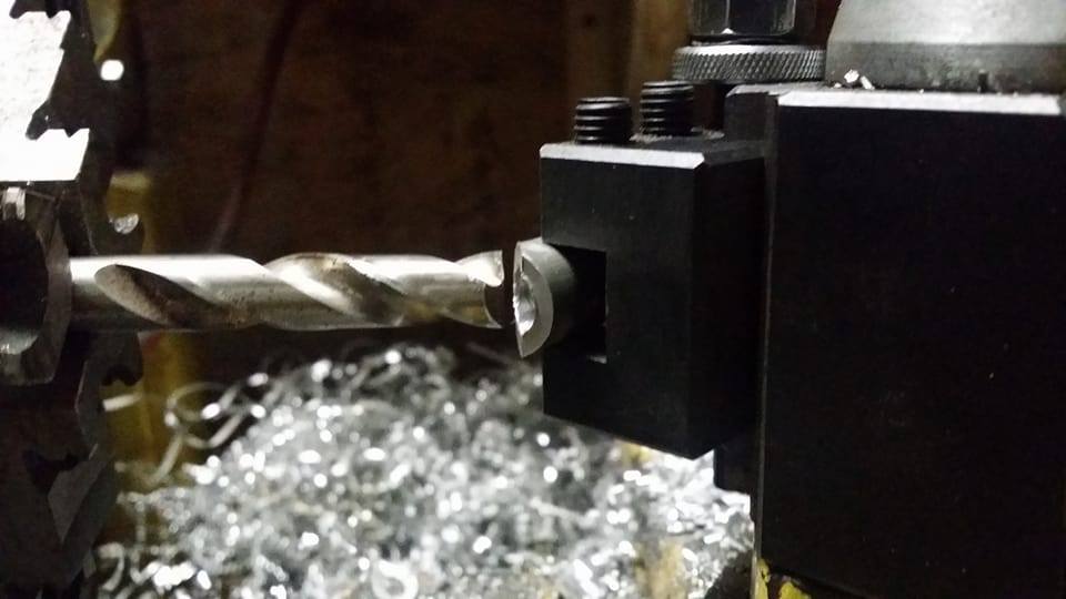
its not the best setup, in fact it kinda sucks and i really wish i had a mill but it got the job done and this part isnt really critical at all.
here it is on the lower. its still not really straight but the main reason for this was to keep my gasket surfaces from getting damaged when i tighten down the rail.
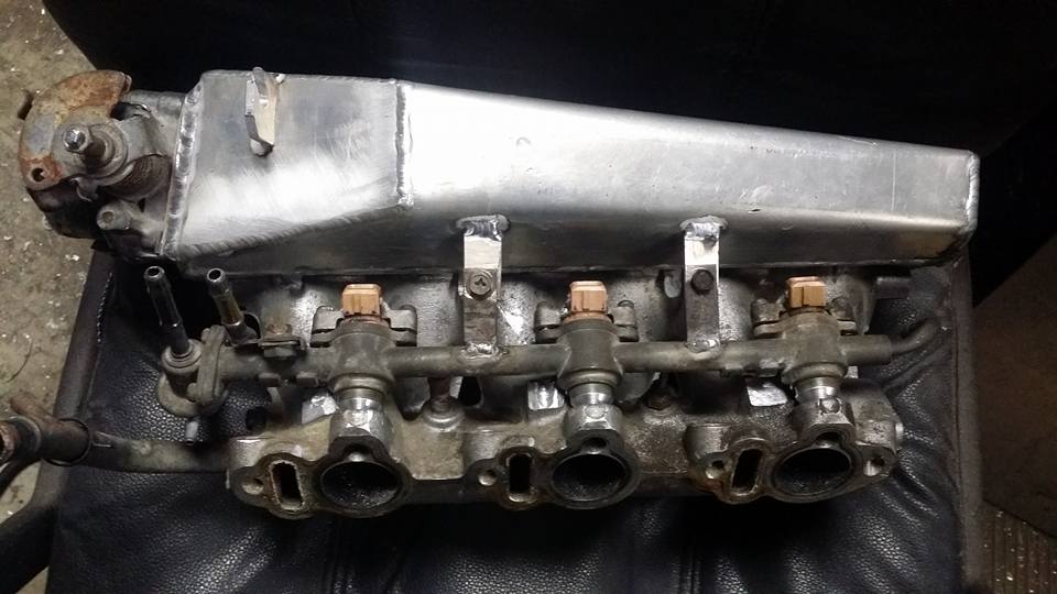
the brackets i made had to fit on top of these spacer things that hold the lower on, in order for them to not hit the little lip i just turned them down in the lathe.
i bolted the brackets to the lower and then clamped the rails down onto the orings to get the compression it would need and then tacked the brackets onto the rail.
i drilled 2 holes in a piece of scrap plate that were exactly 4.250" apart (which is how far apart the holes on the lower are) and used that to locate the other rails brackets with some minor adjustments to get them aligned properly.
heres the other rail done.
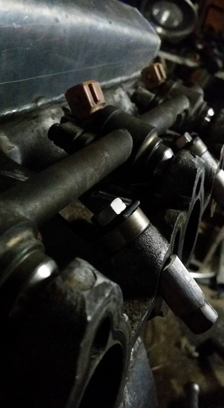
the rear connecting line looks like it will work just fine, i was concerned at first that i would have to bend or cut and reclock these lines when i started on this but thats not going to be necessary.
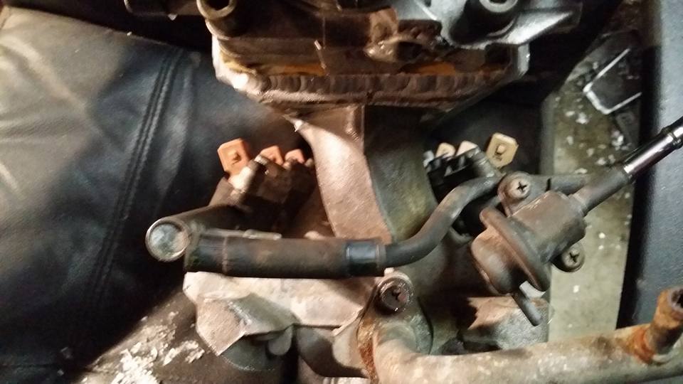
same with the front line.
the next thing ill have to do is probably get some fuel line and new orings. in the mean time while im too broke to buy that stuff ill get working on the coolant stuff and finishing up the wiring harness. hopefully i can source a flywheel for cheap sometime soon cause its getting to be time for me to pull the motor and trans back out for cleaning and final assembly.
i was able to chop off the outside ones with my sawzall but the middle one needed to be drilled into and then cut two more times at an angle. this wont really be visible on the car so i really didnt care what it looks like.
the fuel rails now fit where they will need to go.
obviously the original mounting tabs had to go. i tried drilling out the spot welds on one of them but it turns out the entire tab is brazed onto the rail AND spot welded so i ripped a hole in one of the rails. i welded it up in a minute or so but the rest of them i just chopped off with the sawzall.
i already knew the studs would be really close but after seeing this i knew the ones on my car would actually hit the rails (these ones are just on a jig i made for locating throttle plates on my intakes) cutting the studs down isnt really a big deal tho.
there are several differences between this lower and the maxima lower and the injectors needed to sit a little higher than they would on the maxima. in order to not have to run 2 or 3 injector orings (which would have been a really bad idea) i decided to make up some spacers.
heres one done, 5 more to go.
the cone shape was not for looks, without that extra relief the spacer would have hit the runner. the reason i know this is because the first one i made wasnt cone shaped and it didnt fit lol (pretend the tab isnt there yet, i didnt do everything in the same order im explaining it because my phone was dead for a lot of the work i was doing)
i needed to make an angled adaptor so i could bolt the rails to the lower. i already made the flat tipped drill bit earlier so i could counter sink some other part i was making so i threw that in the chuck and used it like an endmill.
its not the best setup, in fact it kinda sucks and i really wish i had a mill but it got the job done and this part isnt really critical at all.
here it is on the lower. its still not really straight but the main reason for this was to keep my gasket surfaces from getting damaged when i tighten down the rail.
the brackets i made had to fit on top of these spacer things that hold the lower on, in order for them to not hit the little lip i just turned them down in the lathe.
i bolted the brackets to the lower and then clamped the rails down onto the orings to get the compression it would need and then tacked the brackets onto the rail.
i drilled 2 holes in a piece of scrap plate that were exactly 4.250" apart (which is how far apart the holes on the lower are) and used that to locate the other rails brackets with some minor adjustments to get them aligned properly.
heres the other rail done.
the rear connecting line looks like it will work just fine, i was concerned at first that i would have to bend or cut and reclock these lines when i started on this but thats not going to be necessary.
same with the front line.
the next thing ill have to do is probably get some fuel line and new orings. in the mean time while im too broke to buy that stuff ill get working on the coolant stuff and finishing up the wiring harness. hopefully i can source a flywheel for cheap sometime soon cause its getting to be time for me to pull the motor and trans back out for cleaning and final assembly.
Last edited by Nate Boslet; 05-18-2018 at 10:20 AM.
04-15-2017, 06:21 PM
#90
Member
Thread Starter
Join Date: Oct 2016
Posts: 284
after trying to install just one fuel rail onto the car using the system i initially made in the last post i quickly realized this was a MASSIVE pain in the *** and was not going to work out at all and angrily brought everything home so i could try to figure out a different way to get these rails braced.
this is what i came up with.
its not the most elegant solution i know but what it lacks in beauty it makes up for in ease of installation and dissassembly, i can take my rails out and put them back in faster than this car will ever run in the quarter on full boost with nitrous.... in a snowstorm.... also idk why these pictures all came out flipped around, sorry about that but im not taking more and the stupid image hosting site im using wont let me flip them even though there are buttons for it so idk maybe im just an idiot.
font
rear, nothing new here.
ok so now i just have to find some wiring diagram information so i can get the engine harness all finished up, i did the TPS last night and got a few things hooked up where they need to go, i put power to the harness and nothing caught on fire but im not getting power to the ecu or harness but i also know why, the 2 plugs that join the engine harness to the body harness are different, and i dont know what wires are which. if you think you can help or are just interested in following along i started a thread for that specific question: https://maxima.org/forums/3rd-genera...-question.html
Last edited by Nate Boslet; 05-18-2018 at 10:20 AM.
04-19-2017, 08:32 PM
#91
Member
Thread Starter
Join Date: Oct 2016
Posts: 284
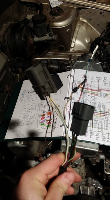
huge thanks to DennisMik for sending me the scans of these two wiring diagrams. legitimately could not have figured this out without those.
this is not all of the diagrams i needed to use, i had to look up a bunch of pinouts and other things (i couldnt find a pinout for the 94 VG30e max but the circuits are all the same or very close so the pins will very likely be doing what they should) i had to print out two copies of both diagrams because i didnt have enough colored markers to make distinguishable highlights and also i used two different methods of highlighting, the first was coloring based off of the colors of the wires and the second was color coding along with the circuits for both cars so that i could just follow them along and be sure which wires needed to be connected together to complete each others circuits.
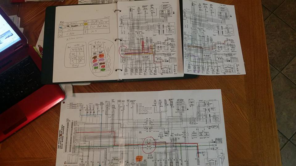
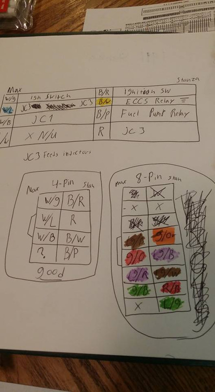
ill probably draw up a more coherent and clear diagram for just in case some other idiot wants to swap a vg30e into their stanza but this is what i ended up with, these are the wires i need to connect in order for the two harnesses to work together. (or at least i hope they are lol) there were only two circuit out of both of these plugs that are completely outside of these plugs so i will have to run wires specially for those but i think most of the important stuff is accounted for.
so next time i go to the garage ill be pulling the motor back out, cleaning everything, doing the remaining gaskets and seals and then final assembly. i have found a brand new flywheel and i already have a basically new clutch and pressure plate. i however dont have a speed sensor for the transmission i will be using. i have one from the stanzas transmission but i dont think its the same or will work so i might be on here looking for a working speed sensor from someone on here. if anyone has one laying around let me know.
this is not all of the diagrams i needed to use, i had to look up a bunch of pinouts and other things (i couldnt find a pinout for the 94 VG30e max but the circuits are all the same or very close so the pins will very likely be doing what they should) i had to print out two copies of both diagrams because i didnt have enough colored markers to make distinguishable highlights and also i used two different methods of highlighting, the first was coloring based off of the colors of the wires and the second was color coding along with the circuits for both cars so that i could just follow them along and be sure which wires needed to be connected together to complete each others circuits.
ill probably draw up a more coherent and clear diagram for just in case some other idiot wants to swap a vg30e into their stanza but this is what i ended up with, these are the wires i need to connect in order for the two harnesses to work together. (or at least i hope they are lol) there were only two circuit out of both of these plugs that are completely outside of these plugs so i will have to run wires specially for those but i think most of the important stuff is accounted for.
so next time i go to the garage ill be pulling the motor back out, cleaning everything, doing the remaining gaskets and seals and then final assembly. i have found a brand new flywheel and i already have a basically new clutch and pressure plate. i however dont have a speed sensor for the transmission i will be using. i have one from the stanzas transmission but i dont think its the same or will work so i might be on here looking for a working speed sensor from someone on here. if anyone has one laying around let me know.
Last edited by Nate Boslet; 05-18-2018 at 10:21 AM.
04-30-2017, 09:50 PM
#92
Member
Thread Starter
Join Date: Oct 2016
Posts: 284
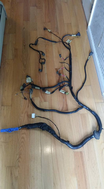
idk if anyone will really be able to tell from the pics but the harness has lost about 5 pounds of extra stuff i wont need.
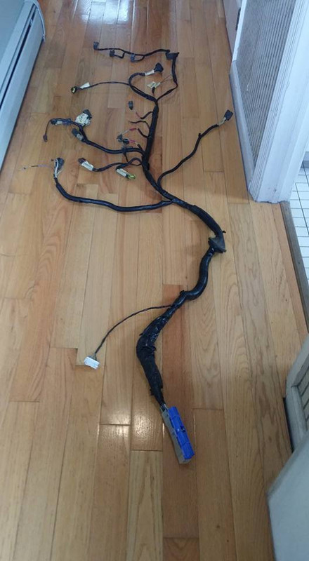
theres even still a thing or two on there that i dont expect to use but i wasnt sure what they were all for and i was mostly focused on the absolutely critical parts of the harness.
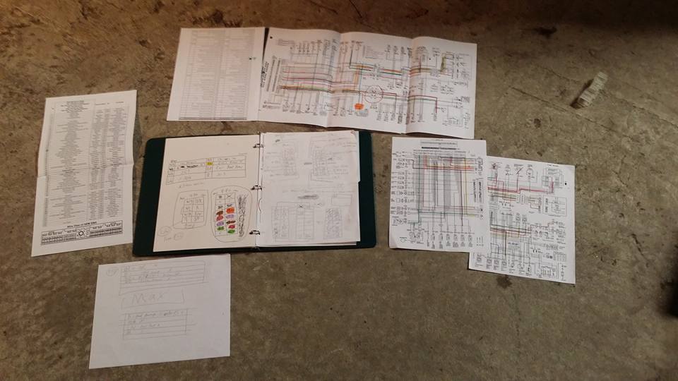
here is a better view of all of the diagrams i used, i made copies of the full engine diagrams so i could color code each wire with my limited amount of colored markers but this is all of the pages i needed besides the two FSM's for each car.
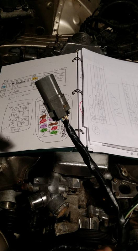
this is the plug where a lot of the more important connections are made, i didnt take pictures of the other plug that i repinned but theres not really much else to see, this is it lol
i already did my homework at home so i knew where all these wires had to connect, i just went through taking out the pins from one plug and putting them into the corresponding hole of the other. piece of cake.
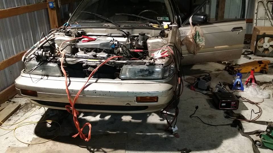
this is how the car is sitting right now. yes those are jumper cables lol i didnt have any alligator jumpers on me, they are just for the grounds and the inhibitor switch that i wasnt sure needed power or not (it did so ill have to run a switched positive for that now)
after installing all the wires and plugs and putting power to everything with my 50amp battery charger i have confirmed that i have power at the harness and ECU. something is wrong tho, the injectors and coil dont fire when the distributor is turned and the fuel pump doesnt come on. the CAS is getting power to its harness and i dont think i changed any of the wires in that part of the harness at all so i dont think its that. im wondering if there is an anti theft or maybe the start or neutral circuit could be making the ECU prevent these things from working. im not sure but i am pretty sure my wiring is all correct. also the starter doesnt turn over, theres no flywheel in the car right now so the motor obviously wont turn over but as far as i can tell my starter circuit is correct. i think there is an anti theft thing that does all this in the Z31 as well which is why i think that may be the issue. ill have to look more into it but once i figure that out and finish up the little things here and there the harness and wiring is basically done.
theres even still a thing or two on there that i dont expect to use but i wasnt sure what they were all for and i was mostly focused on the absolutely critical parts of the harness.
here is a better view of all of the diagrams i used, i made copies of the full engine diagrams so i could color code each wire with my limited amount of colored markers but this is all of the pages i needed besides the two FSM's for each car.
this is the plug where a lot of the more important connections are made, i didnt take pictures of the other plug that i repinned but theres not really much else to see, this is it lol
i already did my homework at home so i knew where all these wires had to connect, i just went through taking out the pins from one plug and putting them into the corresponding hole of the other. piece of cake.
this is how the car is sitting right now. yes those are jumper cables lol i didnt have any alligator jumpers on me, they are just for the grounds and the inhibitor switch that i wasnt sure needed power or not (it did so ill have to run a switched positive for that now)
after installing all the wires and plugs and putting power to everything with my 50amp battery charger i have confirmed that i have power at the harness and ECU. something is wrong tho, the injectors and coil dont fire when the distributor is turned and the fuel pump doesnt come on. the CAS is getting power to its harness and i dont think i changed any of the wires in that part of the harness at all so i dont think its that. im wondering if there is an anti theft or maybe the start or neutral circuit could be making the ECU prevent these things from working. im not sure but i am pretty sure my wiring is all correct. also the starter doesnt turn over, theres no flywheel in the car right now so the motor obviously wont turn over but as far as i can tell my starter circuit is correct. i think there is an anti theft thing that does all this in the Z31 as well which is why i think that may be the issue. ill have to look more into it but once i figure that out and finish up the little things here and there the harness and wiring is basically done.
Last edited by Nate Boslet; 05-18-2018 at 10:21 AM.
05-01-2017, 01:35 PM
#93
Senior Member
Join Date: Apr 2007
Location: Albuquerque, NM
Posts: 1,323
if you ran the ecu with the body harness try unlocking the drivers door with the key, I think the fuel pump relay and such is turned off in the body harness via anti theft other then that you might not have something grounded, like engine to chassis
05-01-2017, 03:02 PM
#94
Member
Thread Starter
Join Date: Oct 2016
Posts: 284
i thought that might be the issue but i hadnt thought about unlocking the car while i was there, ill have to try that tonight. something i forgot to add is the blower motor relay kept clicking on and off but i assumed it was because none of the dash stuff is together or plugged in but according to this link the blower circuit is involved with the anti theft system for some reason.
http://www.commandocaralarms.com/wir...anza/1666.html
im not sure if this information is accurate or relevant but its basically all i could find in regards to the stanzas antitheft system.
are there diagrams for the security system or is it maybe possible to just bypass this circuit entirely? i would rather leave it in just so i dont have to do anything extra but im not really sure where to start since im not sure that circuit is accounted for in the diagrams i have. im gonna look through my pinouts for the ECU and my diagrams for any clues but other than locking and unlocking the doors tonight i dont really have any plans lol i know i havent unlocked the doors while the car had power to it anytime recently so hopefully thats all it is.
05-01-2017, 11:59 PM
#95

i thought that might be the issue but i hadnt thought about unlocking the car while i was there, ill have to try that tonight. something i forgot to add is the blower motor relay kept clicking on and off but i assumed it was because none of the dash stuff is together or plugged in
but according to this link the blower circuit is involved with the anti theft system for some reason.
http://www.commandocaralarms.com/wir...anza/1666.html
im not sure if this information is accurate or relevant but its basically all i could find in regards to the stanzas antitheft system.
http://www.commandocaralarms.com/wir...anza/1666.html
im not sure if this information is accurate or relevant but its basically all i could find in regards to the stanzas antitheft system.
I don't know the Stanza security system, but if it is like the 94 Maxima, all it will do is disable the starter if the alarm is set off.
05-02-2017, 12:07 PM
#96
Member
Thread Starter
Join Date: Oct 2016
Posts: 284
The way I read the stanza wiring diagram, 12 volts goes from a pair of fuses directly to the blower motor. The fan switch in the heater control turns the fan on by connecting it to ground. The switch gets the ground from the blower motor relay. The blower motor relay is energized by the ignition switch being turned to the ON position. Maybe the ground side of the relay's energizing coil is loose. But I don't know where that ground point might be.
The blower motor is definitely is not part of the security system. That chart is a guide for hooking up an aftermarket alarm system and is using the blower motor wire as a source of power for the alarm.
I don't know the Stanza security system, but if it is like the 94 Maxima, all it will do is disable the starter if the alarm is set off.
then my issue must be in my wiring? im going to go back through and retrace my harness. i think i might have missed some more complex areas of the harness that arent being connected together. looking through my diagrams and pages it looks like the circuits i connected together are correct but there are parts of the circuits that are different between the maxima and stanza that i might need to rectify. im going to print out some more copies and fully trace through the whole circuits like i did with the bigger plugs so i know exactly where all the wires are going and get a better idea of where my issues are.
05-02-2017, 09:15 PM
#97
Member
Thread Starter
Join Date: Oct 2016
Posts: 284
OK i just went through my notes and saw what i believe all of my current problems are (at least with the injector and ignition circuits) and they are all pretty easy solutions, i did these circuits first and i dont think i fully started to grasp the diagrams until i was into the second or third plug but i only messed up 2 wires out of the 4. fortunately i can do all of the changes with the harness still on the car so ill probably go do that tomorrow night and make an update then.
05-03-2017, 09:56 AM
#99
Member
Thread Starter
Join Date: Oct 2016
Posts: 284
i may have said this already but im trying to learn as much as i can on my own cars so when i get a job for something like this i have some experience and am more equipped to address these kinds of things quickly and effectively instead of mess up someones car. id rather get mad at myself for a mistake than have someone else be pissed at me lol this is only my 4th motor swap ive been involved in and its the 1st ive ever tried to use a stock harness with, the rest i either wasnt involved in the wiring or i made a completely new harness for a standalone which is considerably easier in my opinion.
Last edited by Nate Boslet; 05-03-2017 at 09:59 AM.
05-03-2017, 09:23 PM
#100
Member
Thread Starter
Join Date: Oct 2016
Posts: 284
I HAVE FUEL AND SPARK!!!!!
that distributor is bad which is why it stopped working part way through, i already knew that one was bad i was just checking which ones worked while it was convenient, i have 2 other ones that work.
the ECU does not turn on or off by the ignition tho, apparently the wire i ran it to is not switched so ill have to fix that and im sure there are some other things in the harness i will need to fix but as far as i can tell if i put everything together and tried; the car would start. i think i need to clean my starter terminals too because only the solenoid is actuating, it doesnt spin right now so ill bring that home this week.
05-03-2017, 09:45 PM
#101
Member
Thread Starter
Join Date: Oct 2016
Posts: 284
i forgot to make an update before, partly because it wasnt really a big deal, its still not a big deal but its a solution to a problem i had so maybe it will be a solution to someone elses problem too.
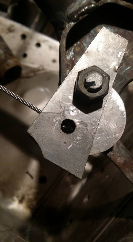
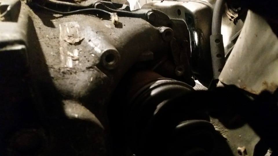
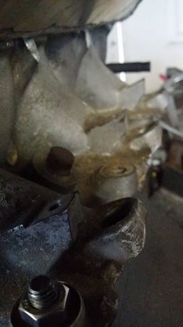
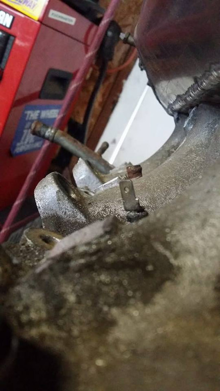
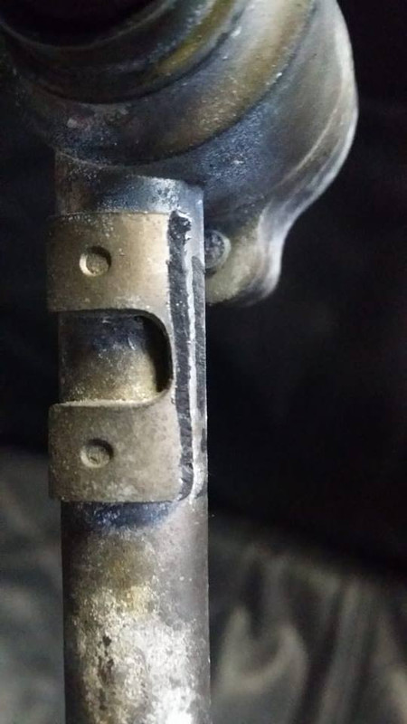
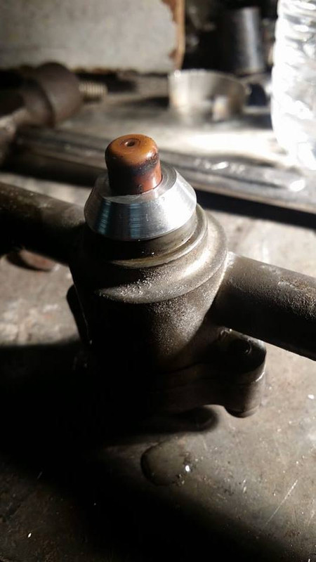
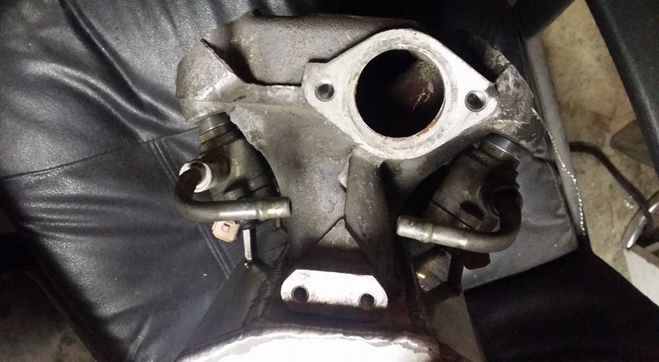
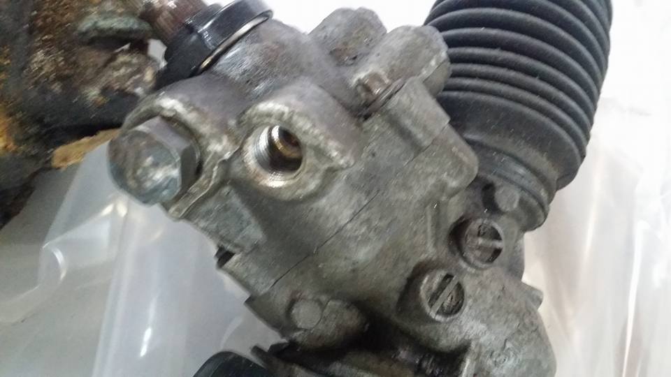
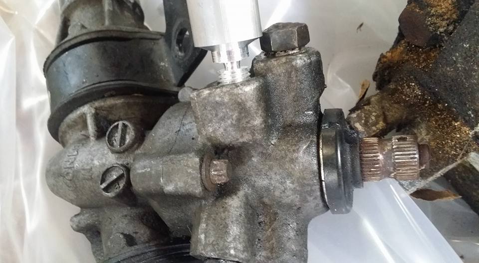
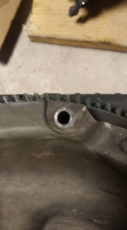
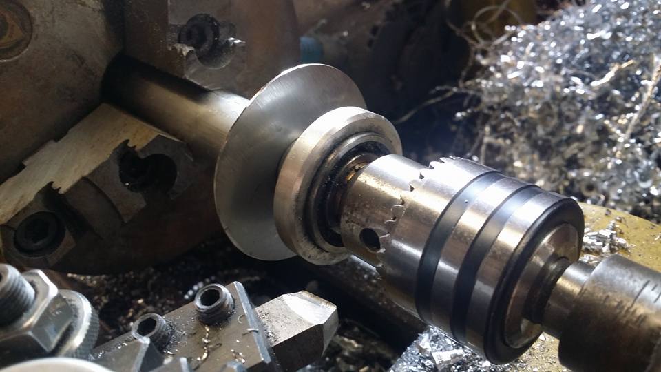
my problem was this threaded hole in my steering rack. idk or remember what happened to the fitting that was here but this hole is 1/2 inch in diameter and appears to be tapered NPT threads. since i didnt have a plug that size i had to make one, since im in the unique position of never needing to unplug this hole ever again i decided it would be much easier to make a plug without a head or socket at all so the plug just goes in and stays in forever, i also didnt want to weld this because of the sensitive components near it like seals and stuff plus its extremely dirty, oil soaked aluminum. so heres what i came up with.
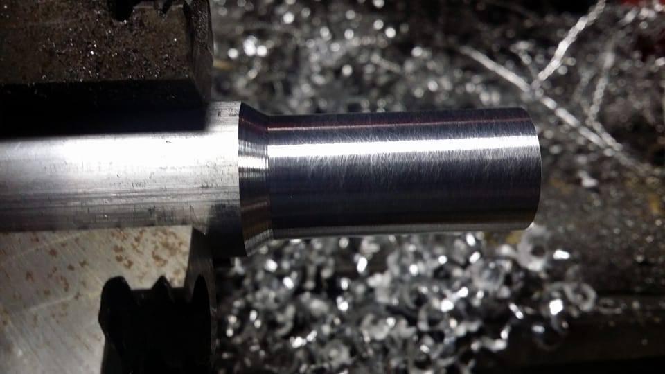
first i needed to thread some aluminum stock so that it fits into the hole, i used a thread gauge to check the pitch and turned the threads on my lathe then i used my parting tool to thin out the section just behind the plug.
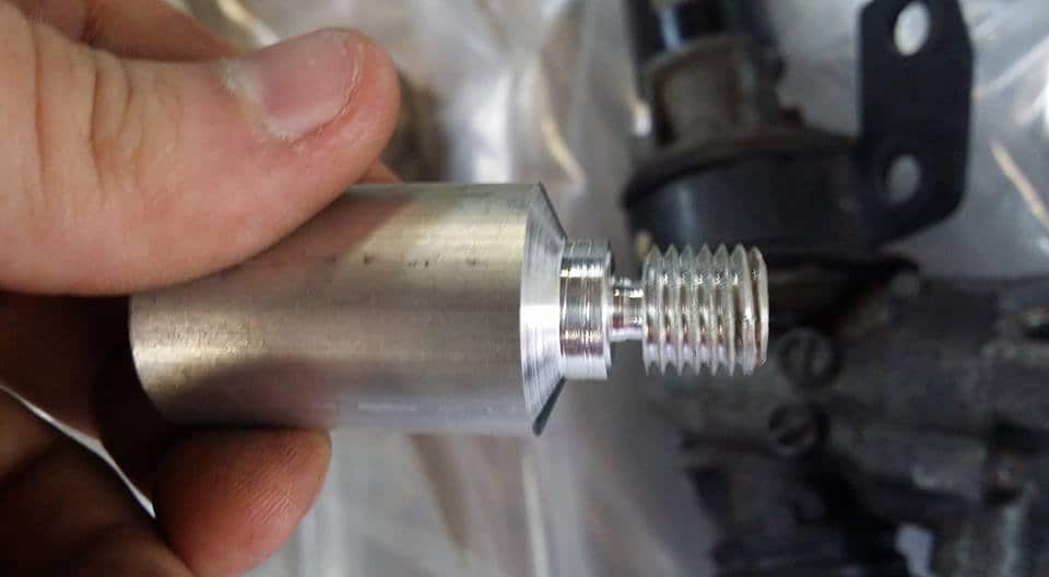
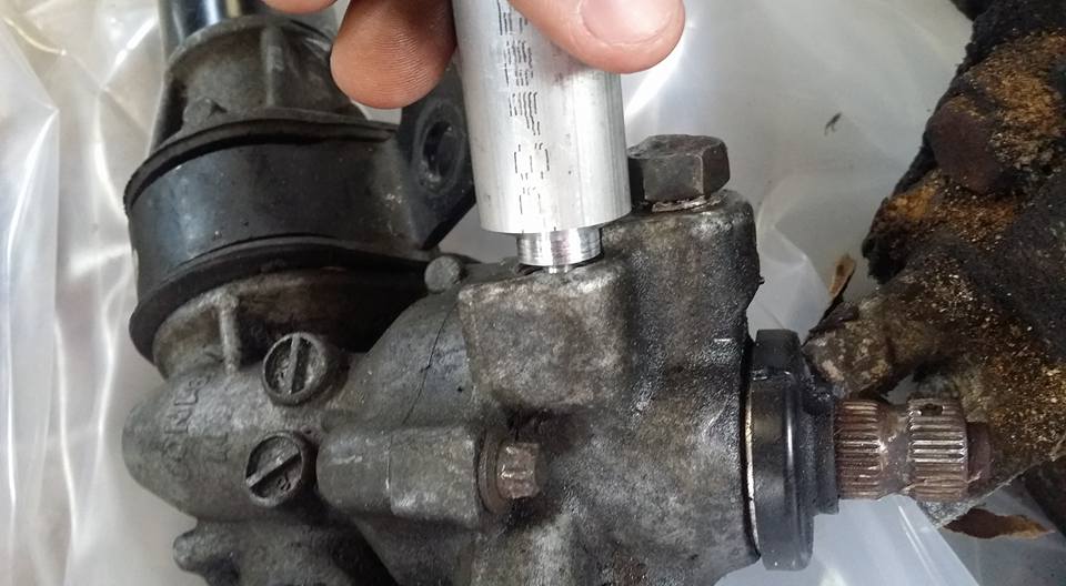
i checked the fit.
it was actually loose as hell because of the taper but it got tighter and tighter as it was threaded in.
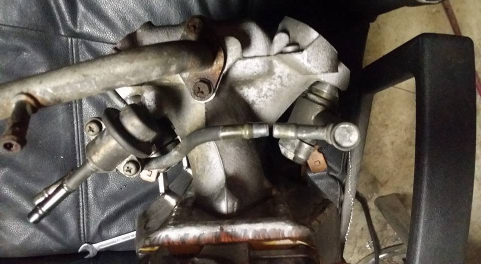
then i needed a way to impart a great deal of torque onto the plug so i drilled a cross hole in the body.
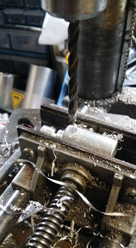
i took a long rod and put it through the cross hole and spun the plug to the bottom and then twisted until the smaller section of the part broke, leaving the plug permanently embedded in the hole. no sealer or tools needed.
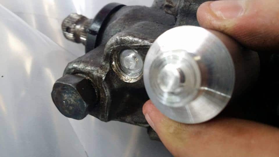
idk if i would recommend doing this on something that is going to see a great deal of pressure but for this particular application it will work just fine. the rack will never see fluid pressure again and the plug is above any conceivable fluid level ill ever fill it to.
my problem was this threaded hole in my steering rack. idk or remember what happened to the fitting that was here but this hole is 1/2 inch in diameter and appears to be tapered NPT threads. since i didnt have a plug that size i had to make one, since im in the unique position of never needing to unplug this hole ever again i decided it would be much easier to make a plug without a head or socket at all so the plug just goes in and stays in forever, i also didnt want to weld this because of the sensitive components near it like seals and stuff plus its extremely dirty, oil soaked aluminum. so heres what i came up with.
first i needed to thread some aluminum stock so that it fits into the hole, i used a thread gauge to check the pitch and turned the threads on my lathe then i used my parting tool to thin out the section just behind the plug.
i checked the fit.
it was actually loose as hell because of the taper but it got tighter and tighter as it was threaded in.
then i needed a way to impart a great deal of torque onto the plug so i drilled a cross hole in the body.
i took a long rod and put it through the cross hole and spun the plug to the bottom and then twisted until the smaller section of the part broke, leaving the plug permanently embedded in the hole. no sealer or tools needed.
idk if i would recommend doing this on something that is going to see a great deal of pressure but for this particular application it will work just fine. the rack will never see fluid pressure again and the plug is above any conceivable fluid level ill ever fill it to.
Last edited by Nate Boslet; 05-18-2018 at 10:22 AM.
05-08-2017, 08:33 AM
#102
Member
Thread Starter
Join Date: Oct 2016
Posts: 284
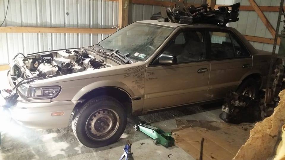
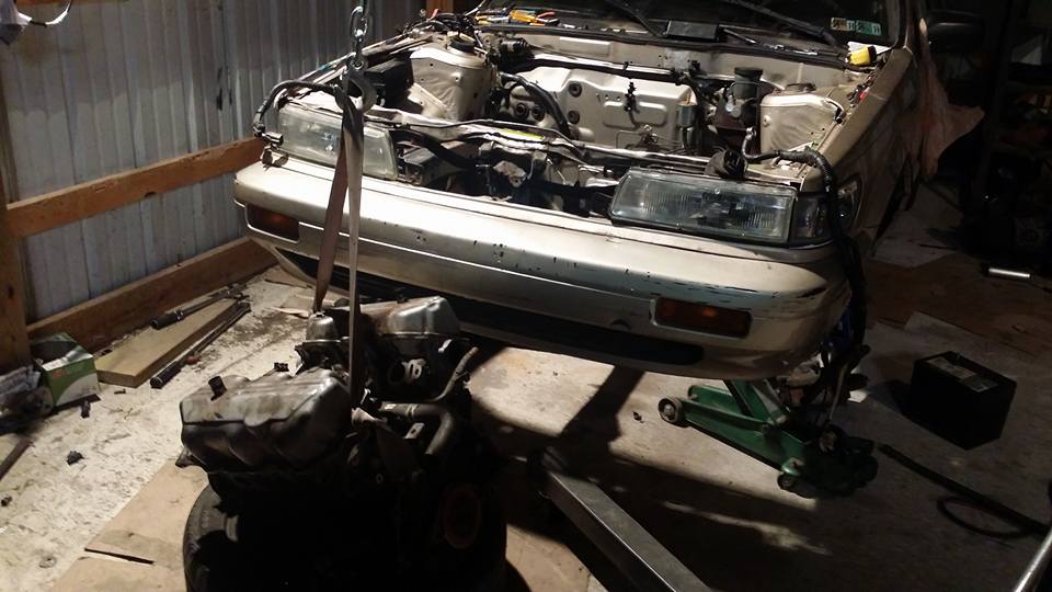
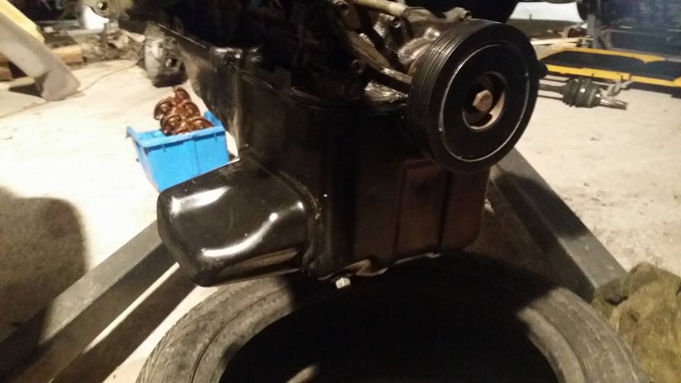
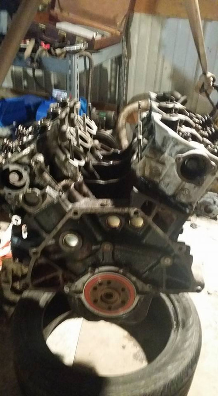
last night i went over to drop some stuff off and decided to start pulling the drivetrain out so i can get the rest of the gaskets and cams and stuff on the motor and trans. i initially planned on waiting till the harness was done but i have all of the major motor stuff worked out so i can do the rest while everything is apart anyway.
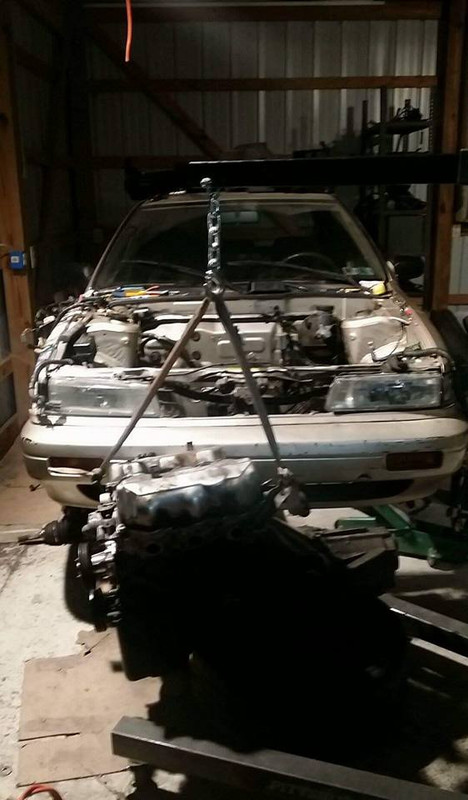
i went from having basically everything in the car it would need to drive to this in an hour, theres so little left and the mounts are so much easier to take out now lol
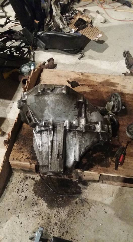
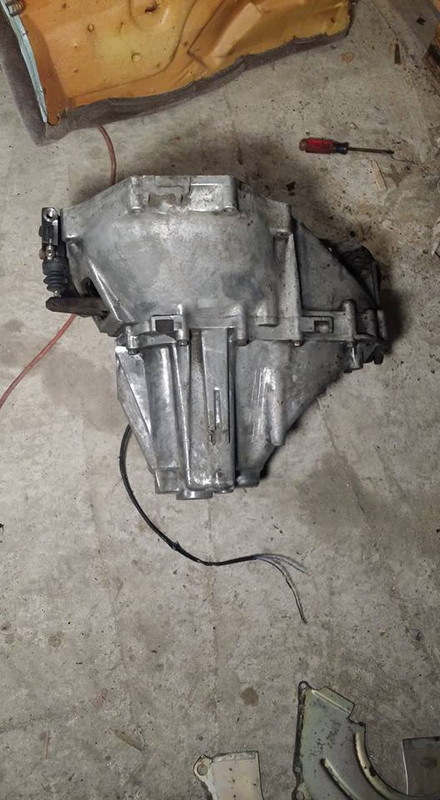
the trans looks like it hasnt been clean in over 30 years....
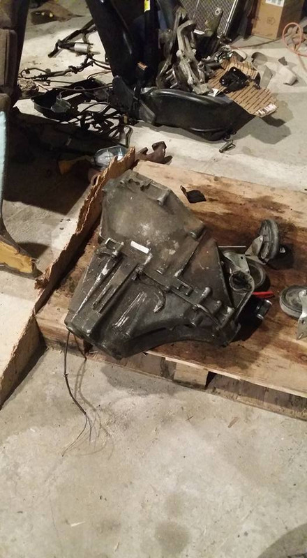
this is it after a good once over, im gonna come back with power tools lol
i ordered my flywheel the other day and i basically just need some more fuel stuff and i should be driving before the month is over. i pulled a speed sensor from my sentra trans and the auto from the other maxima but im not sure either are going to work, if anyone knows if one of these will or wont and where i can get a speed sensor for less than 200 bleeding dollars let me know please lol
i went from having basically everything in the car it would need to drive to this in an hour, theres so little left and the mounts are so much easier to take out now lol
the trans looks like it hasnt been clean in over 30 years....
this is it after a good once over, im gonna come back with power tools lol
i ordered my flywheel the other day and i basically just need some more fuel stuff and i should be driving before the month is over. i pulled a speed sensor from my sentra trans and the auto from the other maxima but im not sure either are going to work, if anyone knows if one of these will or wont and where i can get a speed sensor for less than 200 bleeding dollars let me know please lol
Last edited by Nate Boslet; 05-18-2018 at 10:23 AM.
 05-09-2017, 11:31 PM
#104
Member
Thread Starter
Join Date: Oct 2016
Posts: 284
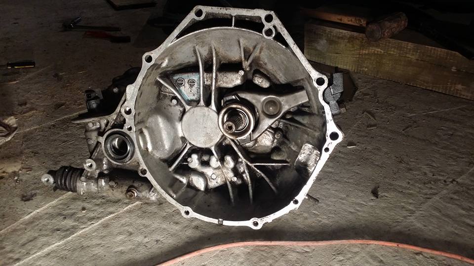
trans is ready to go, i finished up cleaning all the junk off of it and i replaced the axle seals, throwout bearing and slave cylinder.
i couldnt really get the inside as clean as the outside is but im sure it will work just as well and no one will be able to see in there anyway so im ok with that...
im probably gonna get a bunch of **** for this but i did my oil pickup tube while the engine was on my hoist lol i couldnt justify taking my other engine off of my stand just to bring it to the garage to flip this motor over once and then bring it back.
after that was tightened up i put the oil pan gasket and oil pan on (which had a bunch of grey rtv on it that took me like half an hour to clean off) this was significantly more difficult to do while the engine was like this but still only took about 10 minutes and like 3 or 4 swear words to get done.
next went in the maxima cams with some grease.
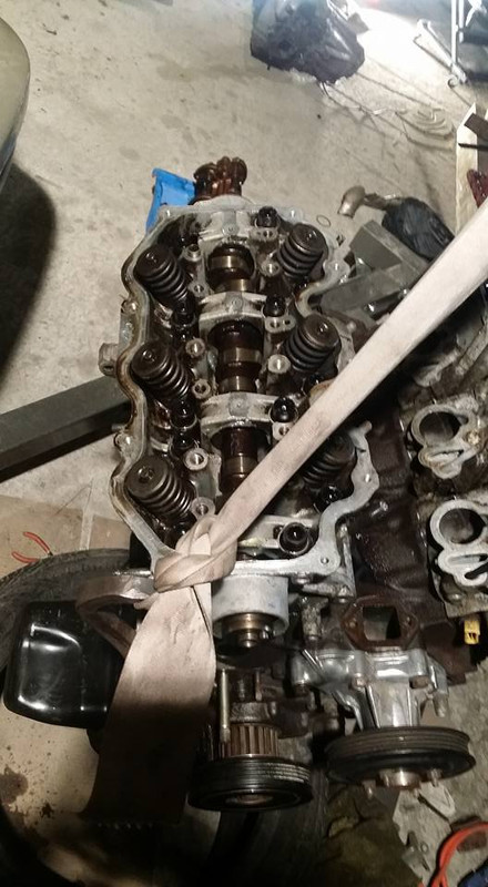
with that i called it a night.
i couldnt really get the inside as clean as the outside is but im sure it will work just as well and no one will be able to see in there anyway so im ok with that...
im probably gonna get a bunch of **** for this but i did my oil pickup tube while the engine was on my hoist lol i couldnt justify taking my other engine off of my stand just to bring it to the garage to flip this motor over once and then bring it back.
after that was tightened up i put the oil pan gasket and oil pan on (which had a bunch of grey rtv on it that took me like half an hour to clean off) this was significantly more difficult to do while the engine was like this but still only took about 10 minutes and like 3 or 4 swear words to get done.
next went in the maxima cams with some grease.
with that i called it a night.
Last edited by Nate Boslet; 05-18-2018 at 10:23 AM.
05-10-2017, 03:12 PM
#105
Member
Thread Starter
Join Date: Oct 2016
Posts: 284
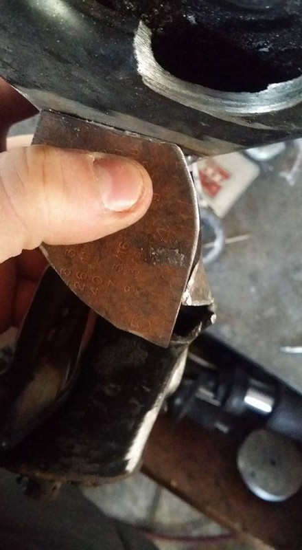
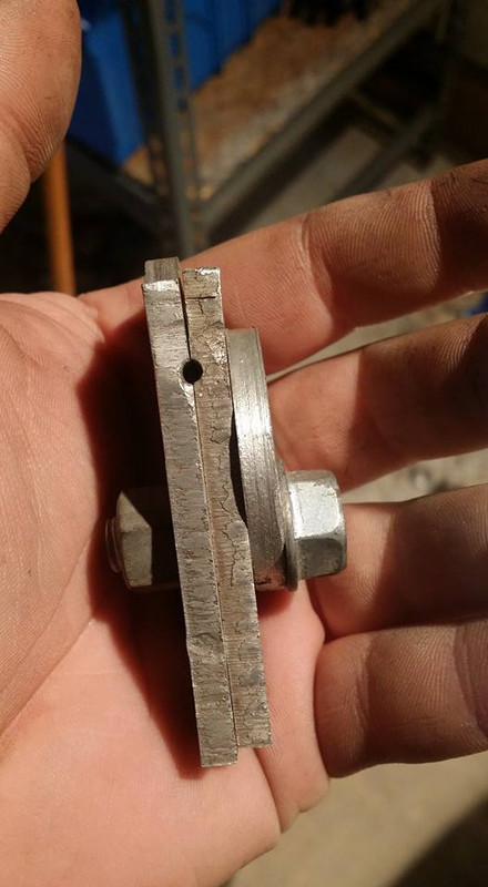
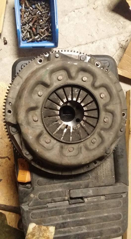
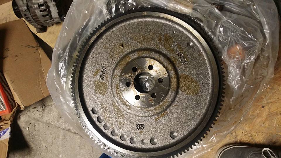
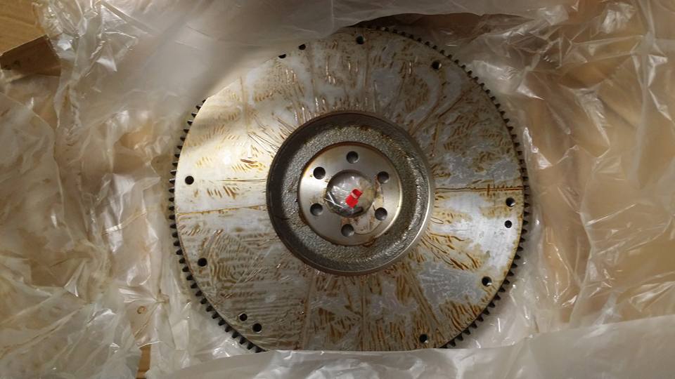
it looks like the z31 pressure plate doesnt fit on my maxima flywheel. its too wide by like maybe a millimeter or so... my other z31 pressure plate doesnt fit either so i dont think its the pressure plate being flexed or anything so either the flywheel is off or the pressure plate from the maxima is a really really slightly different size.
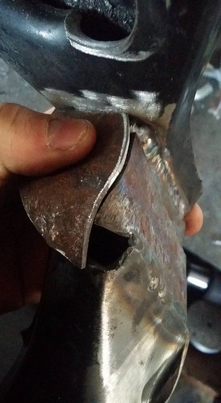
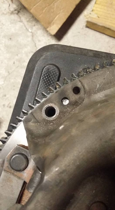
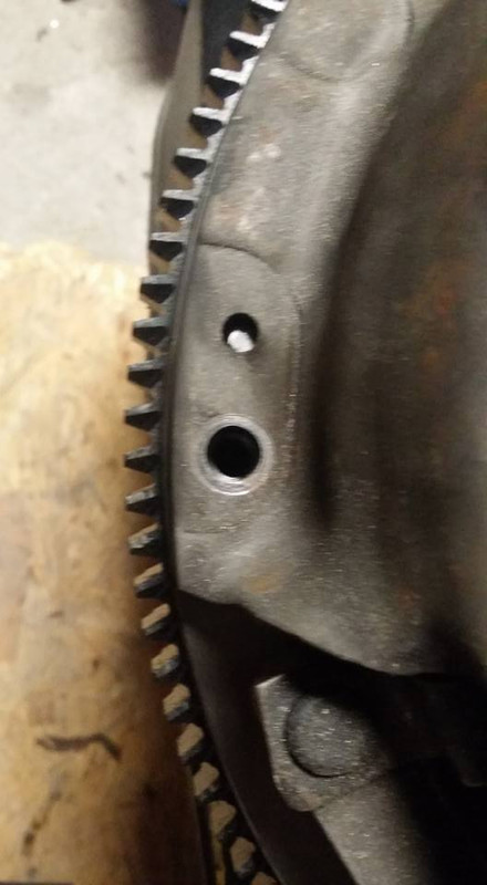
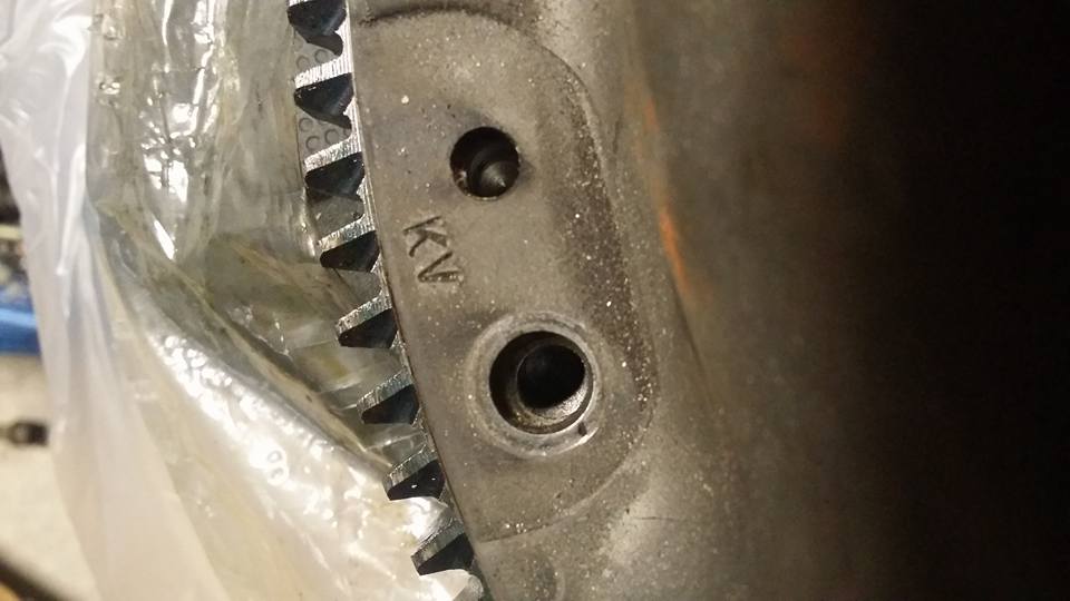
these pics are with the dowel pins in the flywheel, it looks like everything lines up right but the pressure plate wont slip down onto them, when one pin is lined up two others arent, they arent even close. btw my pressure plates all fit the way they are supposed to on my z31 flywheels.
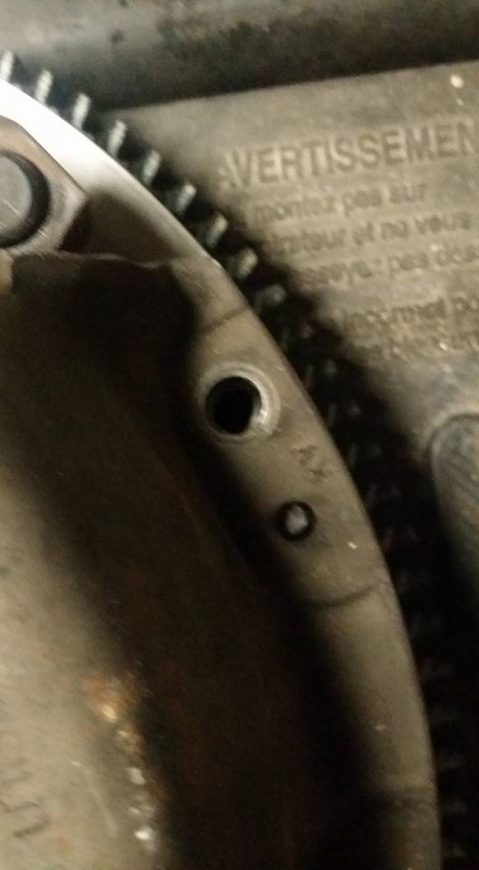
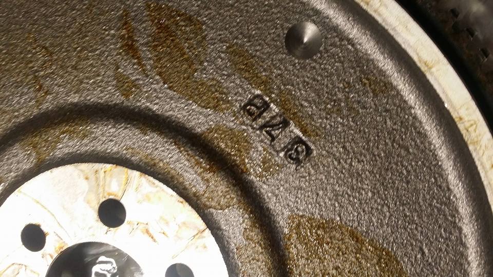
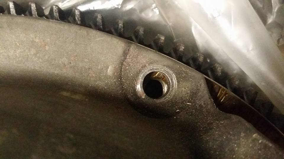
im not sure if any of these markings are significant or not but 37P and 85 are cast into the back of the flywheel.
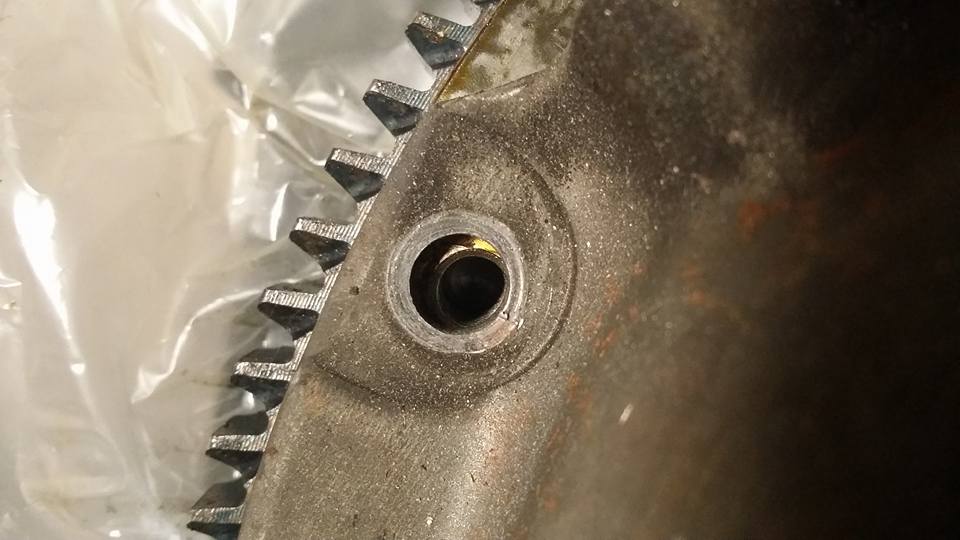
here is a better look at how the bolt holes line up when there is a bolt in two of the holes, the holes on every 3rd of the pressure plate fit exactly as you would expect, its as if the pressure plate has been flattened a little tiny bit and its just slightly too wide now but if it was pushed closer it would fit perfectly..... im also confused because i dont see any reason why nissan would make such a small difference between these two things instead of just make them the same for both models of car.
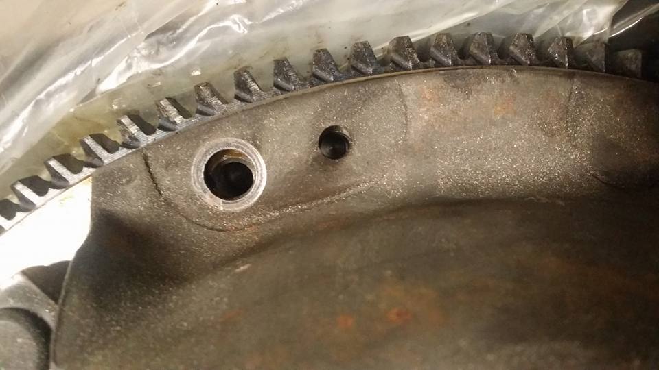
if anyone has had this issue before or has any suggestions on what to do let me know. i am only hesitant to get another pressure plate because im not sure if ill end up with the same issue....
these pics are with the dowel pins in the flywheel, it looks like everything lines up right but the pressure plate wont slip down onto them, when one pin is lined up two others arent, they arent even close. btw my pressure plates all fit the way they are supposed to on my z31 flywheels.
im not sure if any of these markings are significant or not but 37P and 85 are cast into the back of the flywheel.
here is a better look at how the bolt holes line up when there is a bolt in two of the holes, the holes on every 3rd of the pressure plate fit exactly as you would expect, its as if the pressure plate has been flattened a little tiny bit and its just slightly too wide now but if it was pushed closer it would fit perfectly..... im also confused because i dont see any reason why nissan would make such a small difference between these two things instead of just make them the same for both models of car.
if anyone has had this issue before or has any suggestions on what to do let me know. i am only hesitant to get another pressure plate because im not sure if ill end up with the same issue....
Last edited by Nate Boslet; 05-18-2018 at 10:24 AM.
05-18-2017, 11:10 PM
#106
Member
Thread Starter
Join Date: Oct 2016
Posts: 284
while im still working on buying the rest of the parts i need i decided to check out the thermostat that i pulled off that maxima a while back. when i cracked open the housing the tstat looked really old and dirty, the seals on it were all cracked and torn and crusty. ive had thermostats fail in a few of my cars and its blown a headgasket in one of them so i knew i didnt want to just buy some noname part and take that chance, ive taken thermostats out completely but i know that usually just makes the car take a really long time to warm up (particularly if its cold) and then if its really hot outside ive heard that the car will overheat because the coolant doesnt stay in the radiator long enough to actually be cooled down, i drove the stanza while the KA was in it for years with no thermostat and never had any issues even on long trips but the VG apparently runs a lot hotter and i plan on pushing it pretty hard so i want to make sure its running as good as possible, gets up to a reasonable operating temp as fast as possible and stays there as solidly as possible.. so in my research i found that there are a lot of people (mostly people with racecars) that use restrictor plates instead of a thermostat, they are super cheap but this is something i want to install like tomorrow night so i just decided i would make one.
first thing i had to do was cut out a circle in some sheet metal. i used a hole saw to do that. i drilled the middle hole out a little bigger to get it to fit on a mandrel and then i sandwiched it between a live center on my lathe.
i tried to get it as straight and flat as possible many times but every time i would get it close i would try to bend it a little more and **** it all up so i just got it pretty close and turned it. its actually only about .005" out of round, not that it needs to be that accurate at all lol
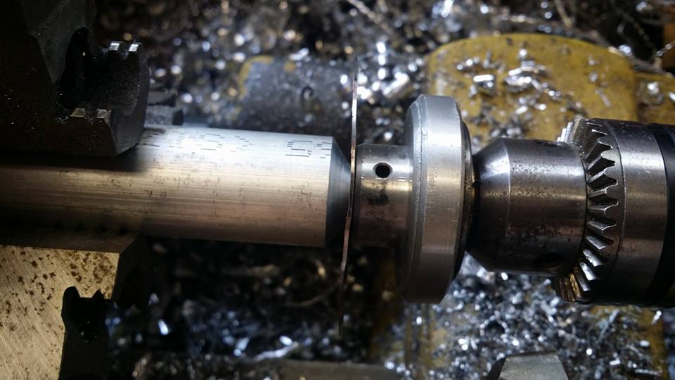
now for the important and very technical part of this extremely simple part, the center hole needs to be a specific size in order to dial in your temps to where you want them. i drilled it slightly smaller than i expect to need it to be so i can just take this out and drill the hole out bigger if i need to lower my temps but im not expecting any significant issues.
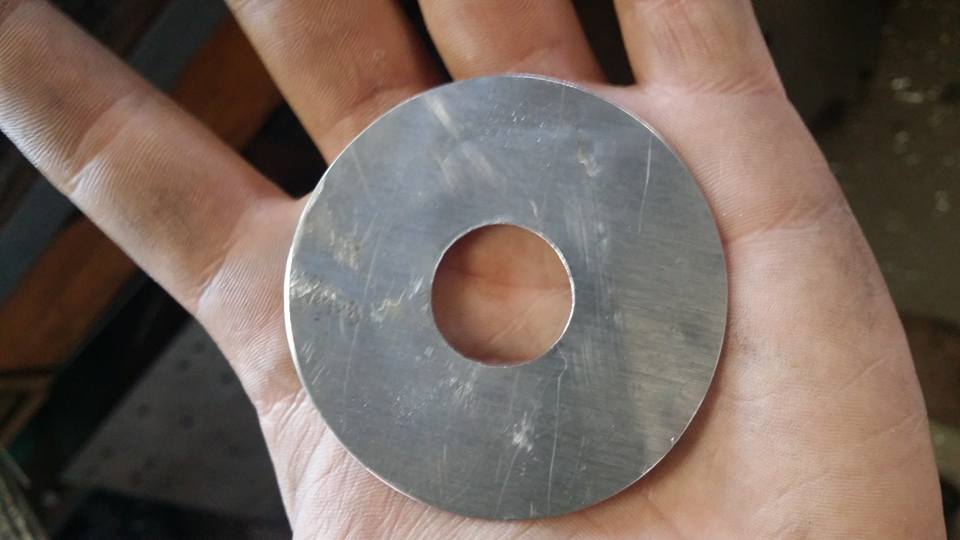
this is the front side of the thermostat housing, you can see the groove the thermostat is supposed to fit inside of, i just measured the diameter of the thermostat that i had and replicated that on the disc. if anyone is interested its 2.520" but i made the disc about .0010" under because it was a little too tight before that.
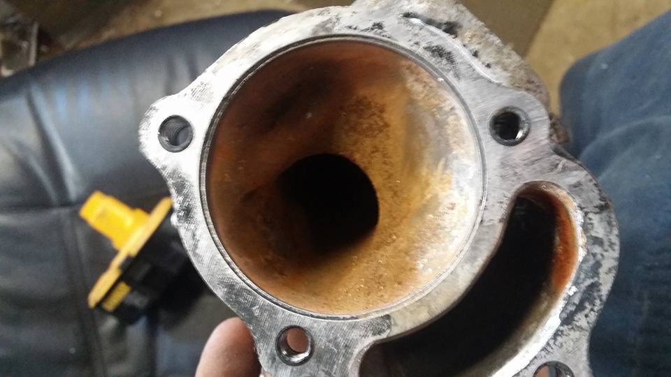
again, the disc isnt flat really so it might not look like it fits very well but its basically exactly the correct size, if i push it down its easier to see. i didnt notice that the sheet i cut it out of was beat up but when its clamped and glued in there with gasket maker its not gonna make a difference.
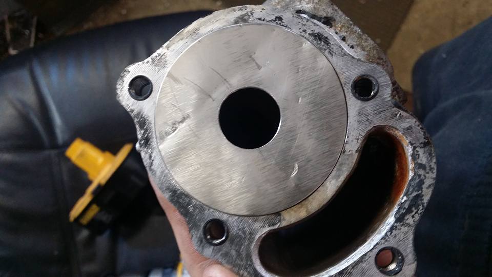
this is the side the thermostat is suppose to like fully fit inside of. there is also a groove on this side for the thermostat to be captive to.
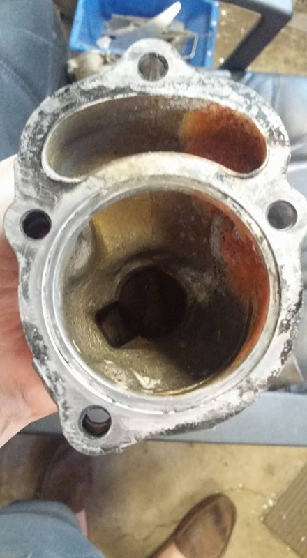
heres the disc in this side.
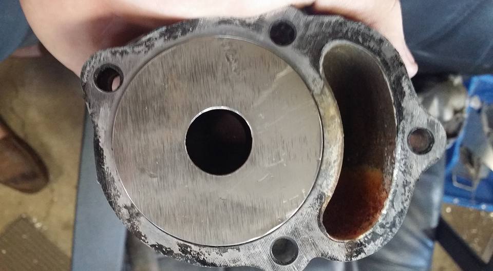
this is kind of a bull**** update, i just basically didnt have anything to do today but i found a basket of goodies in my shed while i was doing this and have a whole bunch to do tomorrow so ill have a much bigger update tomorrow night probably.
first thing i had to do was cut out a circle in some sheet metal. i used a hole saw to do that. i drilled the middle hole out a little bigger to get it to fit on a mandrel and then i sandwiched it between a live center on my lathe.
i tried to get it as straight and flat as possible many times but every time i would get it close i would try to bend it a little more and **** it all up so i just got it pretty close and turned it. its actually only about .005" out of round, not that it needs to be that accurate at all lol
now for the important and very technical part of this extremely simple part, the center hole needs to be a specific size in order to dial in your temps to where you want them. i drilled it slightly smaller than i expect to need it to be so i can just take this out and drill the hole out bigger if i need to lower my temps but im not expecting any significant issues.
this is the front side of the thermostat housing, you can see the groove the thermostat is supposed to fit inside of, i just measured the diameter of the thermostat that i had and replicated that on the disc. if anyone is interested its 2.520" but i made the disc about .0010" under because it was a little too tight before that.
again, the disc isnt flat really so it might not look like it fits very well but its basically exactly the correct size, if i push it down its easier to see. i didnt notice that the sheet i cut it out of was beat up but when its clamped and glued in there with gasket maker its not gonna make a difference.
this is the side the thermostat is suppose to like fully fit inside of. there is also a groove on this side for the thermostat to be captive to.
heres the disc in this side.
this is kind of a bull**** update, i just basically didnt have anything to do today but i found a basket of goodies in my shed while i was doing this and have a whole bunch to do tomorrow so ill have a much bigger update tomorrow night probably.
Last edited by Nate Boslet; 05-18-2018 at 10:24 AM.
 05-20-2017, 11:02 AM
#108
Member
Thread Starter
Join Date: Oct 2016
Posts: 284
so the other day while i was making my thermostat delete thingy i found a whole milk crate full of paint. i was already planning on cleaning everything up and painting a lot of my stuff but i am still waiting to get paid from my job and am too strapped to be spending money on paint so finding some made it possible to do it now lol idk how i missed this stuff for so long it was directly above my work table for probably 3 years lol
anyway i started at home cleaning up the battery tray which had the most rust out of everything.
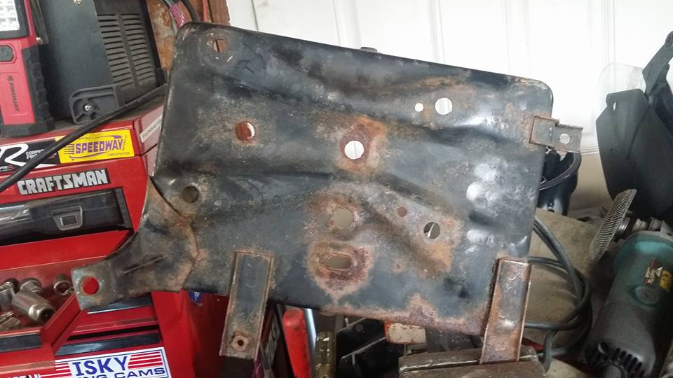
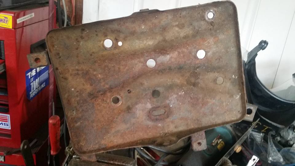
i decided i didnt want to use the tabs hanging off the battery tray, im not really sure what they are for but i know on the stanza there was a fuse box that had to go where they are and i probably deleted whatever went there and am moving the fuse box either under the battery tray or behind it.
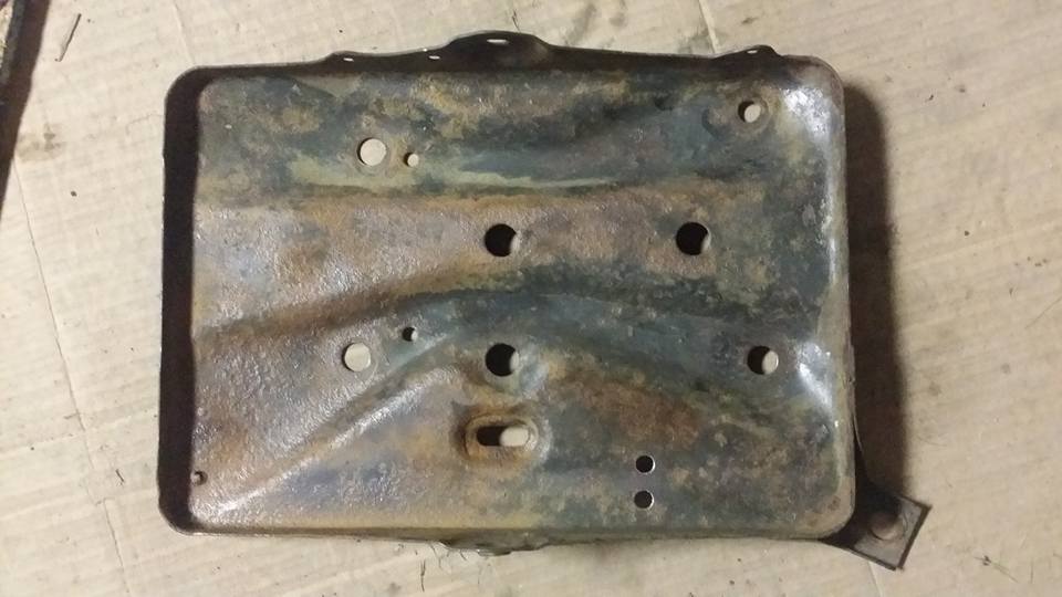
here it is after a real thick coat of paint. idk if i would have picked this color but i actually like it a lot. plus its apparently some kind of industrial performance paint so im pretty stoked about that too.
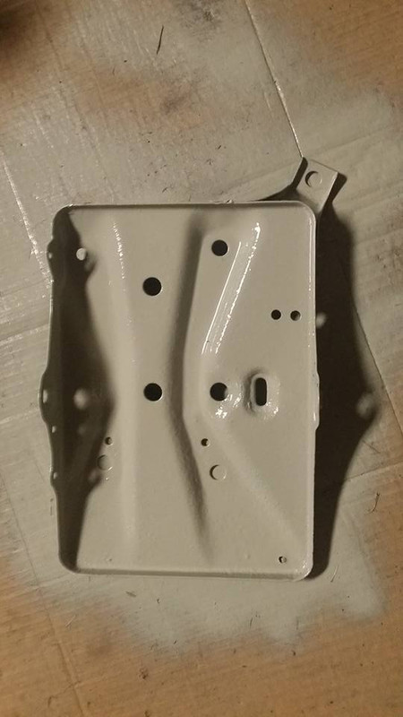
this process was basically just repeated for all the other parts, i cleaned all the oil, dirt, and rust off of everything else and threw at least 2 coats on, this paint went on super thick so all the dirt and junk that was floating around in my shop was covered up by it pretty well.
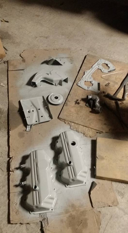
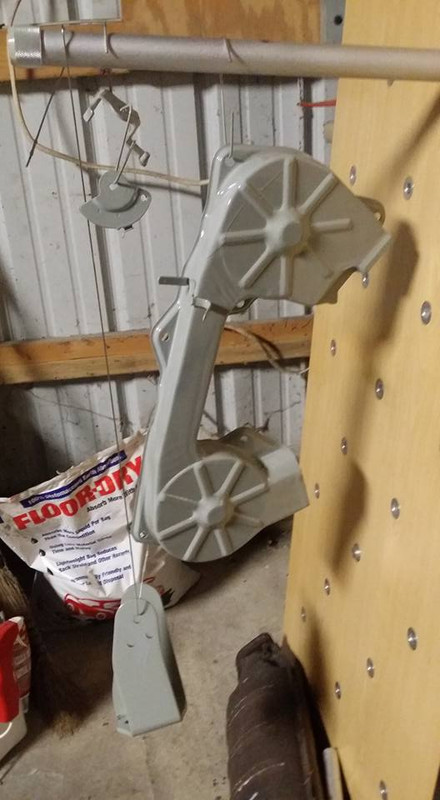
i also used some gasket maker to install the thermostat delete plate and the lower coolant pipe.
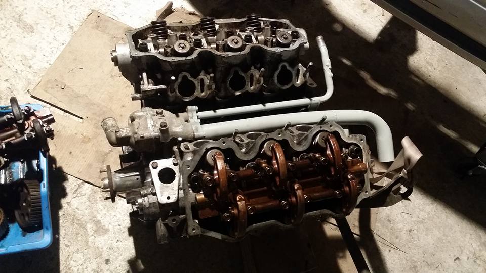
i plan on doing the entire engine bay, im not sure what color yet but i wanted to cover the bare metal spots before i go ahead and spray everything.
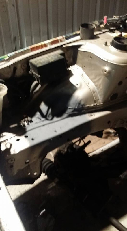
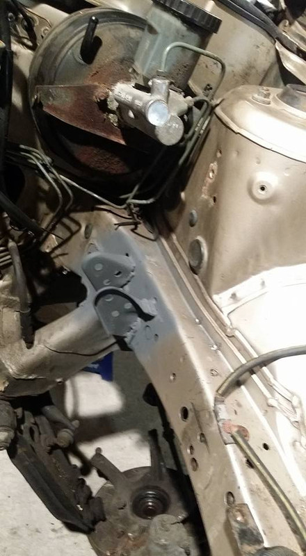
i have a few more things to paint tonight, i wanna try to do the bay but idk if i have a color i want to do it in. (i have flat red, not sure about that though lol) besides that its gonna be a few days until i can order the rest of my parts anyway so painting is about all im gonna be doing for a bit.
anyway i started at home cleaning up the battery tray which had the most rust out of everything.
i decided i didnt want to use the tabs hanging off the battery tray, im not really sure what they are for but i know on the stanza there was a fuse box that had to go where they are and i probably deleted whatever went there and am moving the fuse box either under the battery tray or behind it.
here it is after a real thick coat of paint. idk if i would have picked this color but i actually like it a lot. plus its apparently some kind of industrial performance paint so im pretty stoked about that too.
this process was basically just repeated for all the other parts, i cleaned all the oil, dirt, and rust off of everything else and threw at least 2 coats on, this paint went on super thick so all the dirt and junk that was floating around in my shop was covered up by it pretty well.
i also used some gasket maker to install the thermostat delete plate and the lower coolant pipe.
i plan on doing the entire engine bay, im not sure what color yet but i wanted to cover the bare metal spots before i go ahead and spray everything.
i have a few more things to paint tonight, i wanna try to do the bay but idk if i have a color i want to do it in. (i have flat red, not sure about that though lol) besides that its gonna be a few days until i can order the rest of my parts anyway so painting is about all im gonna be doing for a bit.
Last edited by Nate Boslet; 05-18-2018 at 10:25 AM.
05-22-2017, 02:06 PM
#109
Member
Thread Starter
Join Date: Oct 2016
Posts: 284
here are some of the painted parts on the motor. i took these pics the other day and forgot to post them, i have a lot more stuff i am going to take pictures of tonight so im just making this post to catch up. not much to say besides for free, 15 year old paint it looks pretty good lol
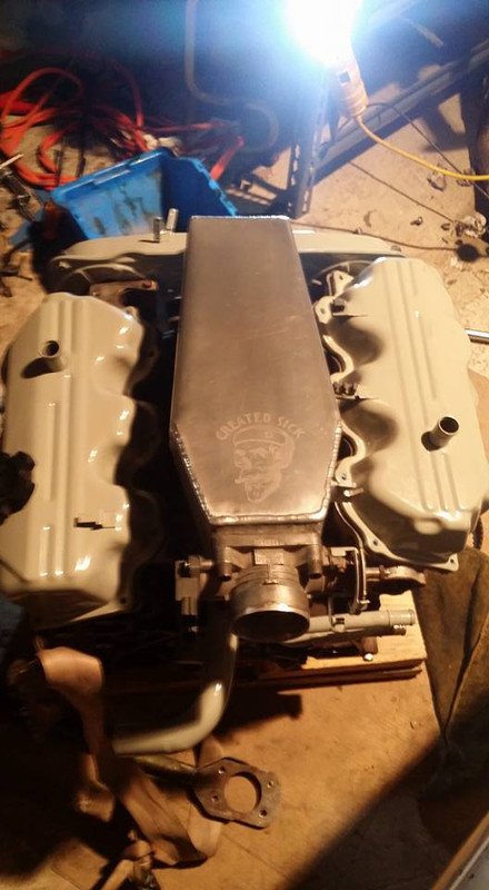
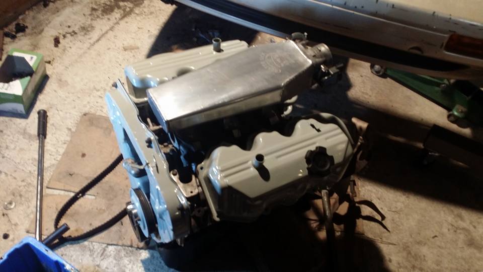
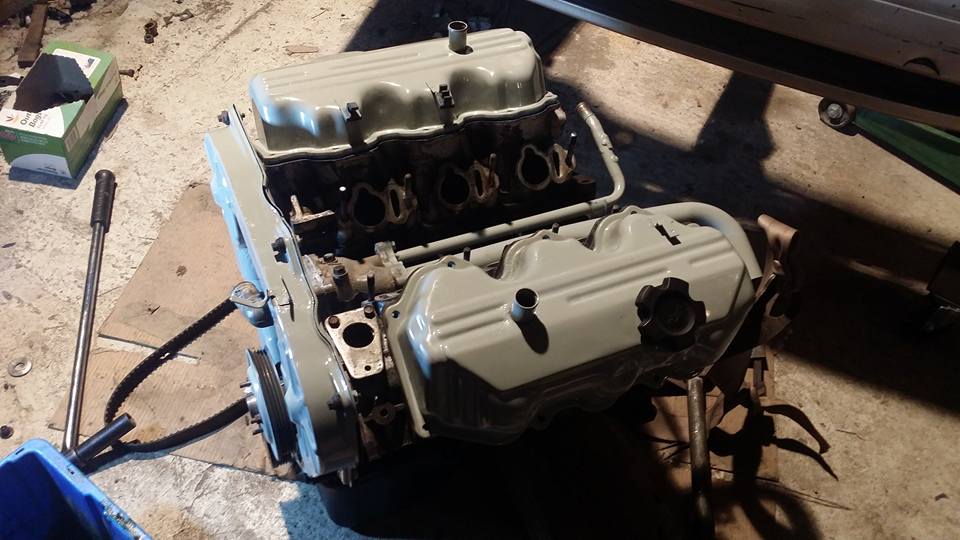
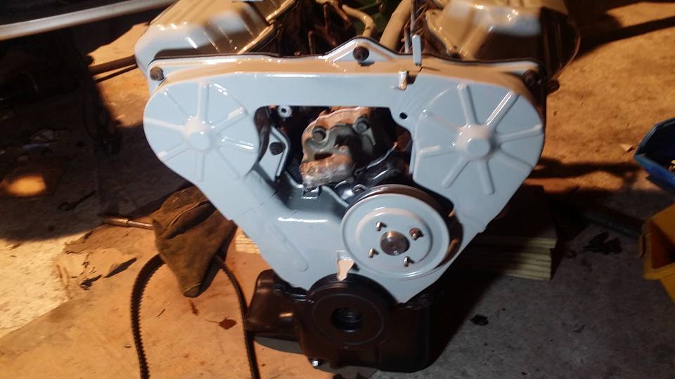

the motor should be basically done tonight besides fuel. im gonna try to order the pressure plate and stuff tonight also so i can see if this thing will start. in the mean time i am gonna be prepping the engine bay for paint. im pretty stoked to see how all this stuff looks back together, ive never painted so many different little things in my life lol
the motor should be basically done tonight besides fuel. im gonna try to order the pressure plate and stuff tonight also so i can see if this thing will start. in the mean time i am gonna be prepping the engine bay for paint. im pretty stoked to see how all this stuff looks back together, ive never painted so many different little things in my life lol
Last edited by Nate Boslet; 05-18-2018 at 10:26 AM.
05-23-2017, 07:01 AM
#110

About your pressure plate - honestly, if it were me, I would just enlarge the bolt holes on the pressure plate slightly with a drill and call it done. With the holes opened up just very slightly it certainly seems it would allow the bolts to thread into the flywheel.
05-23-2017, 10:21 AM
#111
Member
Thread Starter
Join Date: Oct 2016
Posts: 284
im worried that will introduce play into the pressure plate, the dowel pins dont line up either so i would have to drill those bigger as well if there is any movement in there a failure would be inevitable. a new pressure plate is only like 45 bucks on rockauto so i think im just gonna go that way.
05-23-2017, 10:59 AM
#112
Member
Thread Starter
Join Date: Oct 2016
Posts: 284
here is the timing belt done, the marks dont line up because i turned the motor over a few times to make sure it was working.
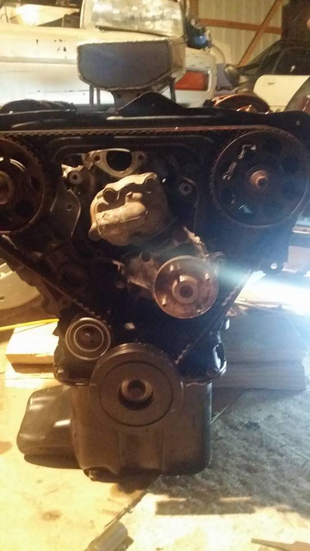
motor mount brackets
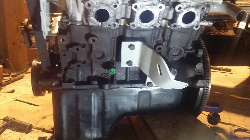
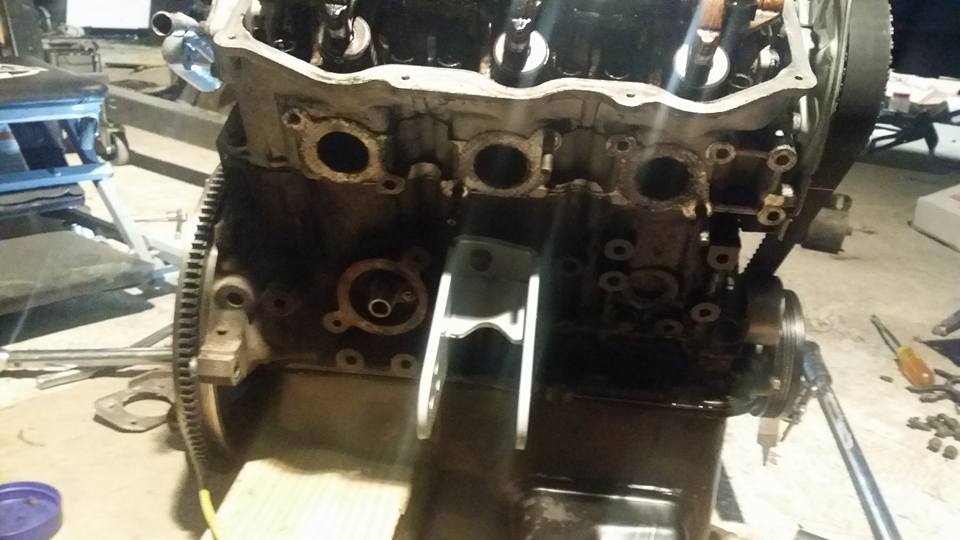
brake booster
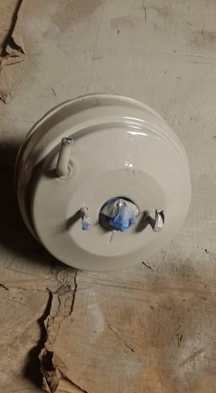
transmission mount bracket
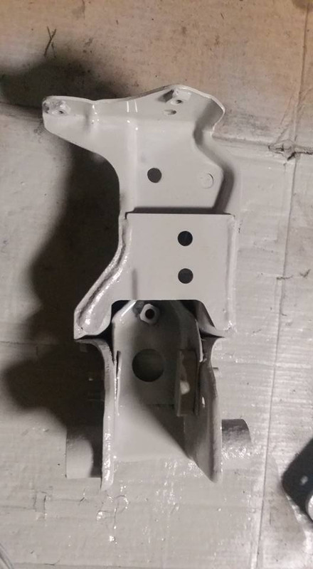
transmission mount
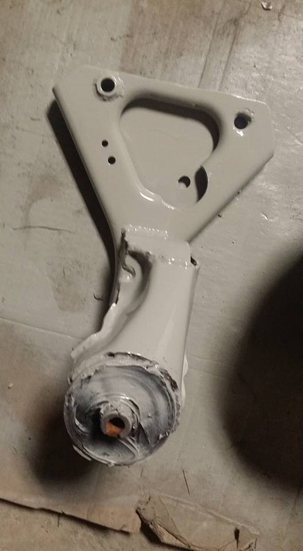
alternator bracket
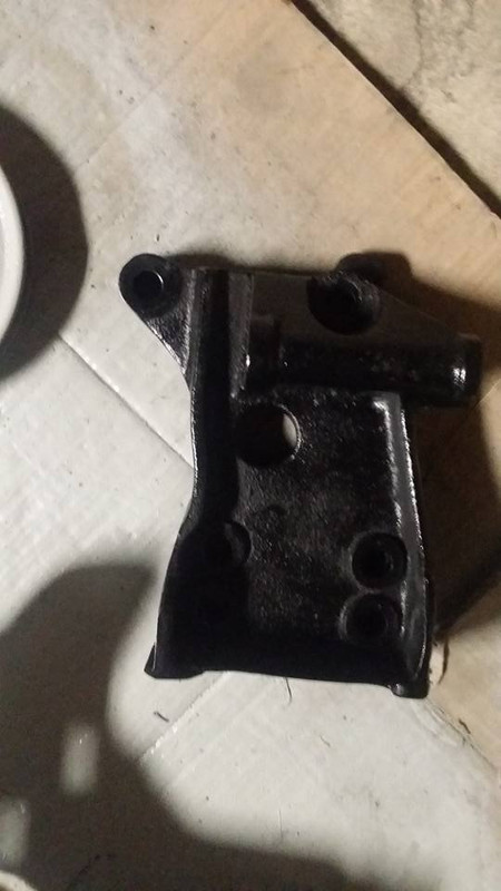
bay prep
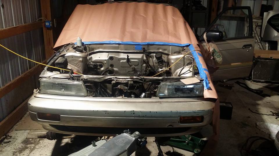
windshield wiper motor
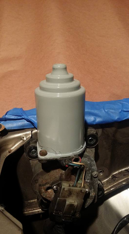
this is the potential engine bay color, its flat red. im not 100% sure on it yet but idk ill have to get a second or third opinion before im really confident about it lol
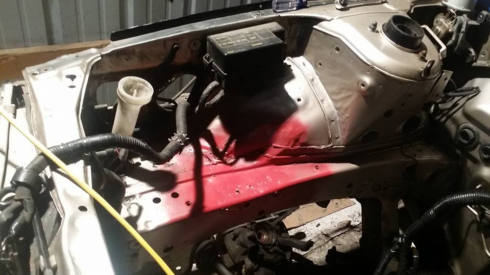
motor mount brackets
brake booster
transmission mount bracket
transmission mount
alternator bracket
bay prep
windshield wiper motor
this is the potential engine bay color, its flat red. im not 100% sure on it yet but idk ill have to get a second or third opinion before im really confident about it lol
Last edited by Nate Boslet; 05-18-2018 at 10:26 AM.
05-28-2017, 04:21 PM
#113
Member
Thread Starter
Join Date: Oct 2016
Posts: 284
initially i had just planned on spraying the whole bay one color and while i think that would have been fine and looked good an artist friend of mine wanted to do a new project, going along with the theme of this car i said she can do basically whatever she wants in the engine bay because i dont care lol
but before we could paint, of course we had to prep. here is the bay after 3 passes with degreaser and 2 passes of paint thinner, there were a few spots where there was like tree sap or something that had to be scraped off with a razor blade but it wasnt too bad since i already got most of the huge piles of dirt out of it.
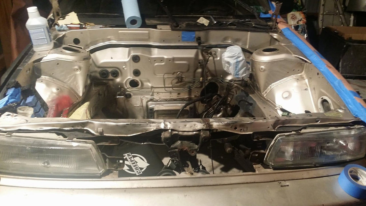
after we had finished cleaning we started sanding everything and then i decided i wanted to bondo over this section of the frame rail that was really beaten up. its not perfect or anything but it looks a lot better than it did before, i didnt do some of the other places because it would have taken way too much bondo to fill in so i just left them and ill probably just cover them up with my coil or a coolant reservior later.
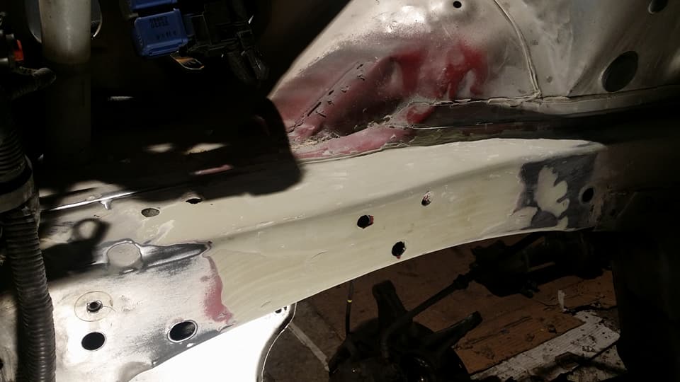
here is the bay after the first coat. you probably cant tell from the picture but this was all done by hand (she wanted to do it this way to cut down on prep and to keep more control) it looks great in person, i actually like the subtle brush strokes but she says they will probably fill in after the other coats are on.
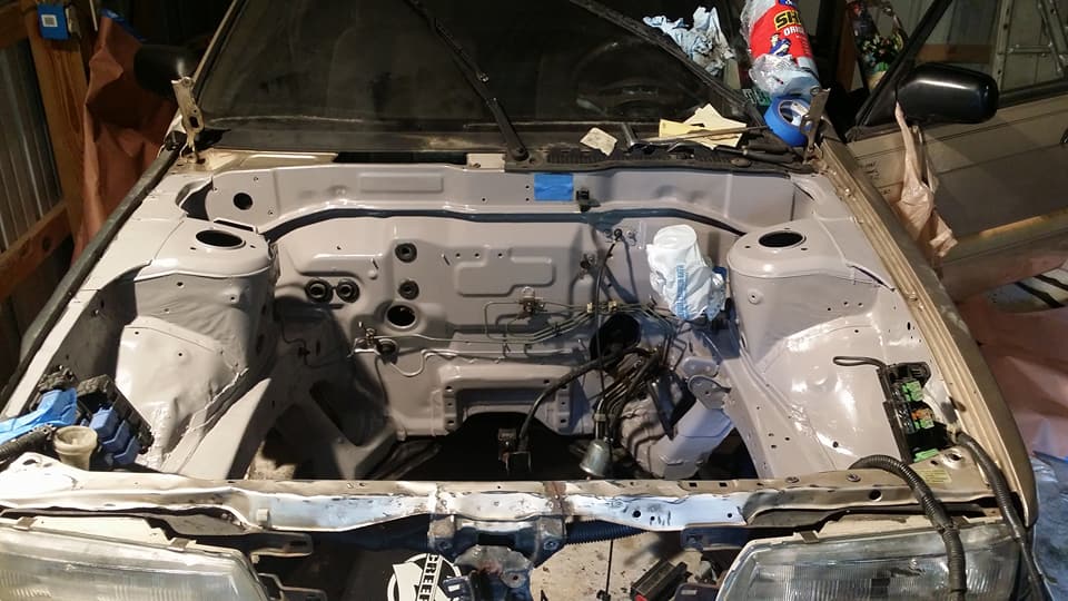
probably should have gotten better lighting here but the bondo came out alright.
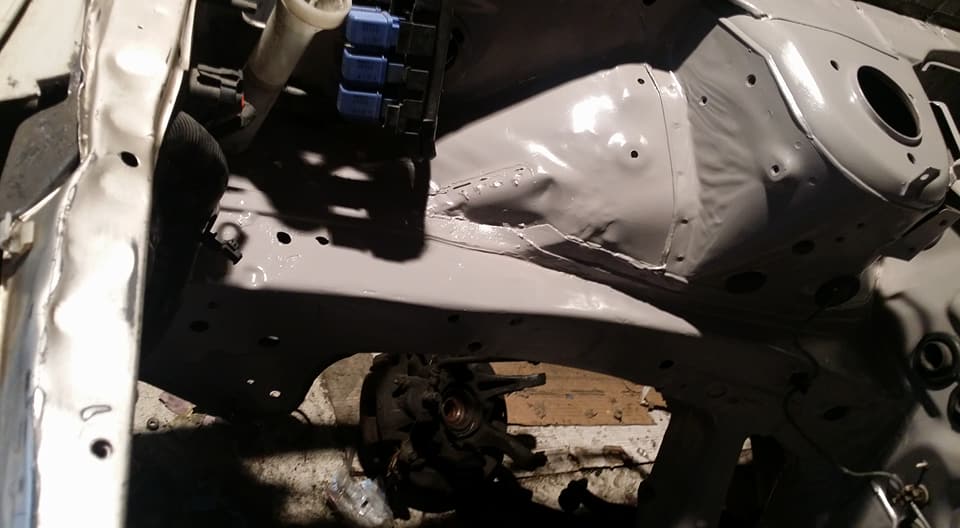
the upper core support in the front is also going to be painted it just is gonna get painted last because shes like fully inside of the engine bay when shes painting.
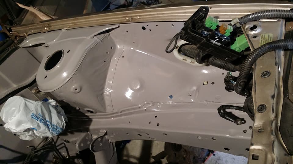
i was supposed to get my pressure plate yesterday but i guess ill be getting it tomorrow now so ill throw that stuff back together and continue prepping the engine to go back into the car, i still need a few more little things and fluids but other than that once the paint is done i should be able to see if it will run! the paint should be done next weekend so maybe another week or so after that.
but before we could paint, of course we had to prep. here is the bay after 3 passes with degreaser and 2 passes of paint thinner, there were a few spots where there was like tree sap or something that had to be scraped off with a razor blade but it wasnt too bad since i already got most of the huge piles of dirt out of it.
after we had finished cleaning we started sanding everything and then i decided i wanted to bondo over this section of the frame rail that was really beaten up. its not perfect or anything but it looks a lot better than it did before, i didnt do some of the other places because it would have taken way too much bondo to fill in so i just left them and ill probably just cover them up with my coil or a coolant reservior later.
here is the bay after the first coat. you probably cant tell from the picture but this was all done by hand (she wanted to do it this way to cut down on prep and to keep more control) it looks great in person, i actually like the subtle brush strokes but she says they will probably fill in after the other coats are on.
probably should have gotten better lighting here but the bondo came out alright.
the upper core support in the front is also going to be painted it just is gonna get painted last because shes like fully inside of the engine bay when shes painting.
i was supposed to get my pressure plate yesterday but i guess ill be getting it tomorrow now so ill throw that stuff back together and continue prepping the engine to go back into the car, i still need a few more little things and fluids but other than that once the paint is done i should be able to see if it will run! the paint should be done next weekend so maybe another week or so after that.
Last edited by Nate Boslet; 05-18-2018 at 10:27 AM.
06-01-2017, 12:36 PM
#114
Member
Thread Starter
Join Date: Oct 2016
Posts: 284
i finally got my parts in the mail after fedex missing my house 3 times... i wanted to get my mounts filled asap so they have plenty of time to fully cure before they go into the car.
this is the basic idea behind the front engine mount. the reason i did it this way is because just putting a hockey puck with a bolt through it in the front will not behave as an isolator, it would be almost exactly the same as a solid mount because the bolt is transferring all the vibration directly from the engine to the frame, with this design there is always at least 1 inch of soft material the vibrations need to go through before they can be absorbed into the body of the car and rattle my interior pieces. interior noise was a big concern of mine when i started this build, i want it to feel like a completely stock car in basically every way so going from the 4cyl with a solid torque mount to this should be pretty dramatic. i had planned on just using an oem rubber mount but this turned out to be cheaper and will last longer and be plenty strong enough for the power levels i hope to reach when the car is turbo.
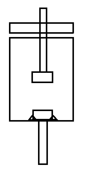
i filled the bottom first about as much as i wanted between the bolt and the bottom of the cup, stuck the bolt in and then filled the rest. simple. im gonna cut down the lower bolt later dont worry lol
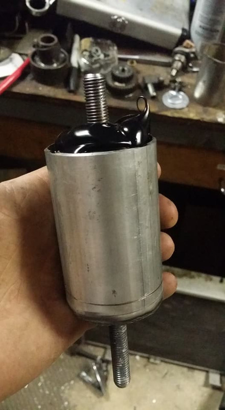
i used this giant washer as something for the engine to rest on, i will probably have to weld the bolt to it later in order to keep the bolt from pulling up when i tighten it on. if i was to do this again i would have welded the washer on first and then just drilled a hole in the cup to fill it up, since i didnt think of doing that before ill have to do what i can to get this one right or ill just tear it apart and redo it, im not sure yet but you get the idea.
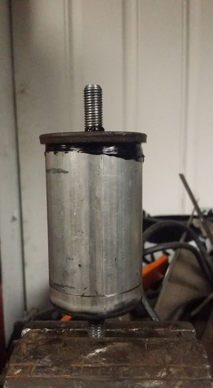
next was the rear trans mount. same basic process just with a sleeve inside of the tube thats open on both ends.
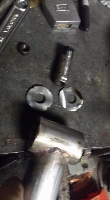
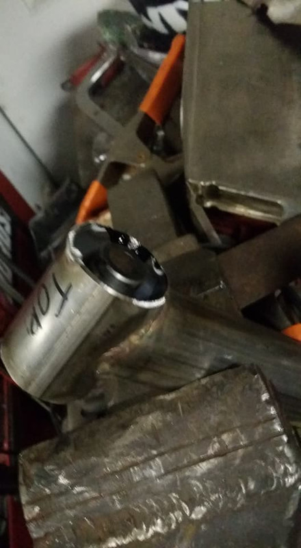
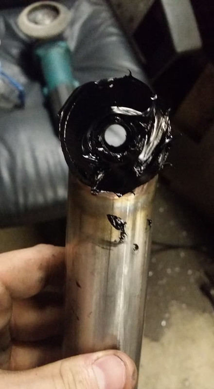
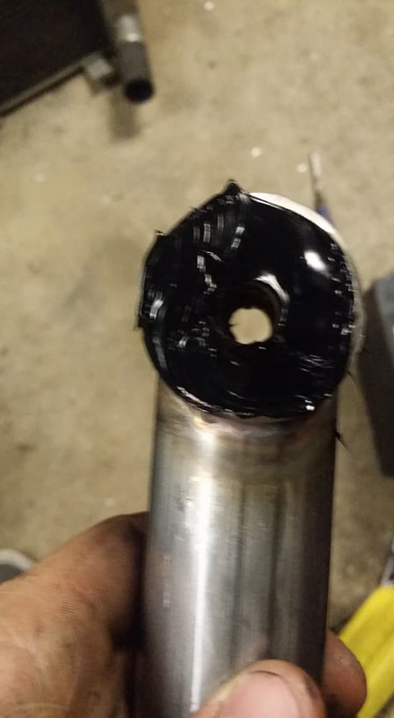
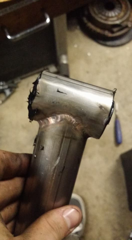
im going to trim off the excess and then throw some paint on them. i got my pressure plate in so i can install that and then mate the trans and engine back together, the engine bay should be finished this weekend and then everything will go back together, in the mean time today i should be finishing up my fuel rail stuff with orings and paint so ill post another update on that soon.
this is the basic idea behind the front engine mount. the reason i did it this way is because just putting a hockey puck with a bolt through it in the front will not behave as an isolator, it would be almost exactly the same as a solid mount because the bolt is transferring all the vibration directly from the engine to the frame, with this design there is always at least 1 inch of soft material the vibrations need to go through before they can be absorbed into the body of the car and rattle my interior pieces. interior noise was a big concern of mine when i started this build, i want it to feel like a completely stock car in basically every way so going from the 4cyl with a solid torque mount to this should be pretty dramatic. i had planned on just using an oem rubber mount but this turned out to be cheaper and will last longer and be plenty strong enough for the power levels i hope to reach when the car is turbo.
i filled the bottom first about as much as i wanted between the bolt and the bottom of the cup, stuck the bolt in and then filled the rest. simple. im gonna cut down the lower bolt later dont worry lol
i used this giant washer as something for the engine to rest on, i will probably have to weld the bolt to it later in order to keep the bolt from pulling up when i tighten it on. if i was to do this again i would have welded the washer on first and then just drilled a hole in the cup to fill it up, since i didnt think of doing that before ill have to do what i can to get this one right or ill just tear it apart and redo it, im not sure yet but you get the idea.
next was the rear trans mount. same basic process just with a sleeve inside of the tube thats open on both ends.
im going to trim off the excess and then throw some paint on them. i got my pressure plate in so i can install that and then mate the trans and engine back together, the engine bay should be finished this weekend and then everything will go back together, in the mean time today i should be finishing up my fuel rail stuff with orings and paint so ill post another update on that soon.
Last edited by Nate Boslet; 05-18-2018 at 10:28 AM.
06-01-2017, 10:56 PM
#115
Member
Thread Starter
Join Date: Oct 2016
Posts: 284
i pulled my starter the rest of the way apart to try to find any reasons why it wont spin... everything on the inside looks great to me, nothing is really worn or excessively dirty. im gonna give it a really good cleaning and see if i can get it to work on the bench.
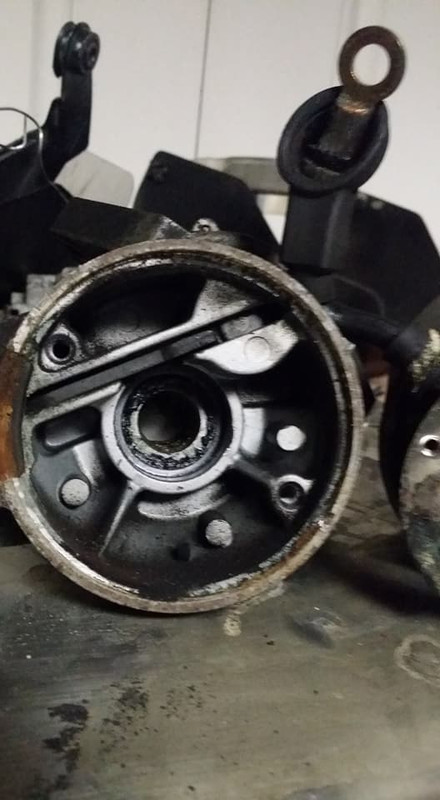
the brushes almost look new which is good cause they dont look easy to replace.
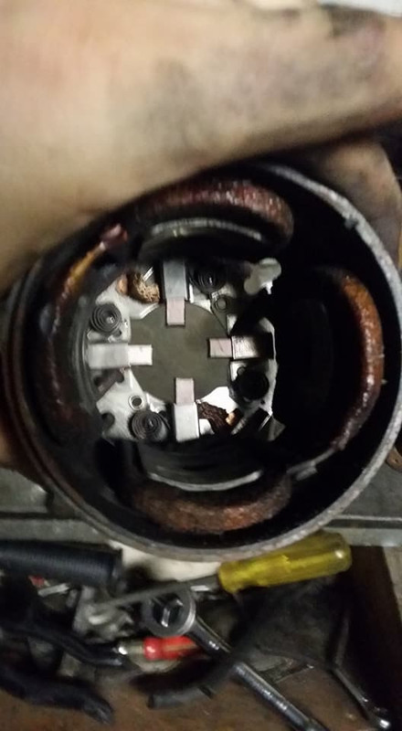
the contacts on the commutator look a little worn down, i think i will attempt to clean it up as best i can maybe with some sandpaper on my lathe.
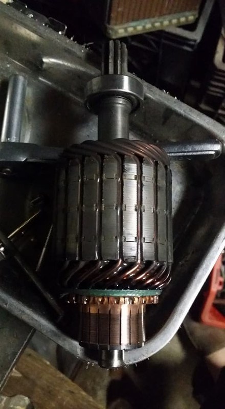
like i said i got my pressure plate today so i made sure that fit on my flywheel and fortunately it does, i made sure my z31 clutch will work with it and it looks like it will work just fine but before i can install it i needed to make a clutch alignment tool.
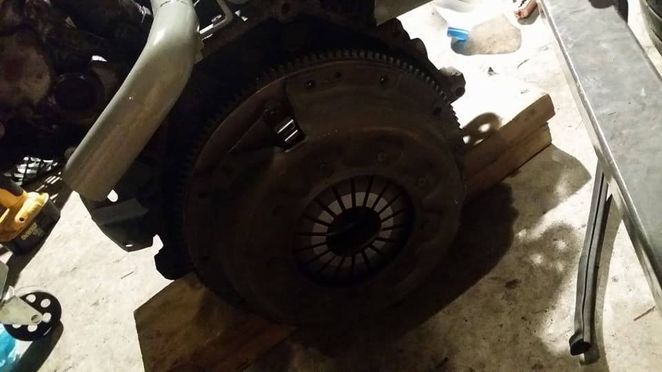
here is the finished tool. the smaller diameter has been turned to fit inside of the pilot bearing in my crank (you guys probably dont have a pilot bearing because the maxima trans doesnt have a pilot shaft to go into one) and the larger diameter slides inside of the splined section of the clutch, just like a regular clutch alignment too. the tool doesnt need to be splined, im not really sure why they go through the trouble of doing that but this tool should be much more accurate than one of those plastic ones you normally get.
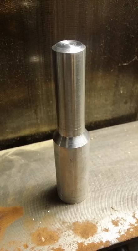
tomorrow i will have the starter back together and hopefully doing some more painting.
the brushes almost look new which is good cause they dont look easy to replace.
the contacts on the commutator look a little worn down, i think i will attempt to clean it up as best i can maybe with some sandpaper on my lathe.
like i said i got my pressure plate today so i made sure that fit on my flywheel and fortunately it does, i made sure my z31 clutch will work with it and it looks like it will work just fine but before i can install it i needed to make a clutch alignment tool.
here is the finished tool. the smaller diameter has been turned to fit inside of the pilot bearing in my crank (you guys probably dont have a pilot bearing because the maxima trans doesnt have a pilot shaft to go into one) and the larger diameter slides inside of the splined section of the clutch, just like a regular clutch alignment too. the tool doesnt need to be splined, im not really sure why they go through the trouble of doing that but this tool should be much more accurate than one of those plastic ones you normally get.
tomorrow i will have the starter back together and hopefully doing some more painting.
Last edited by Nate Boslet; 05-18-2018 at 10:29 AM.
06-02-2017, 08:08 PM
#117
Member
Thread Starter
Join Date: Oct 2016
Posts: 284
its from the 94 i pulled a bunch of stuff off of a while ago. i have one of the regular ones too i bought from starks2010 before i got the hookup on the maxima, the only reason im using the one with the lump is because its shorter.
06-03-2017, 07:25 PM
#118
Member
Thread Starter
Join Date: Oct 2016
Posts: 284
i couldnt wait to see my clutch alignment tool in action so the first thing i did yesterday was head over and install my clutch. i didnt actually know the inner measurement for the pilot bearing when i made it because the one on the motor was beat out of spec from the abuse of whoever was driving that z31 lol BUT i bought a new pilot bearing before i realized i didnt need it because the maxima trans doesnt use one so i took my measurement off of that and added 5 thou to the overall diameter and it fit well.
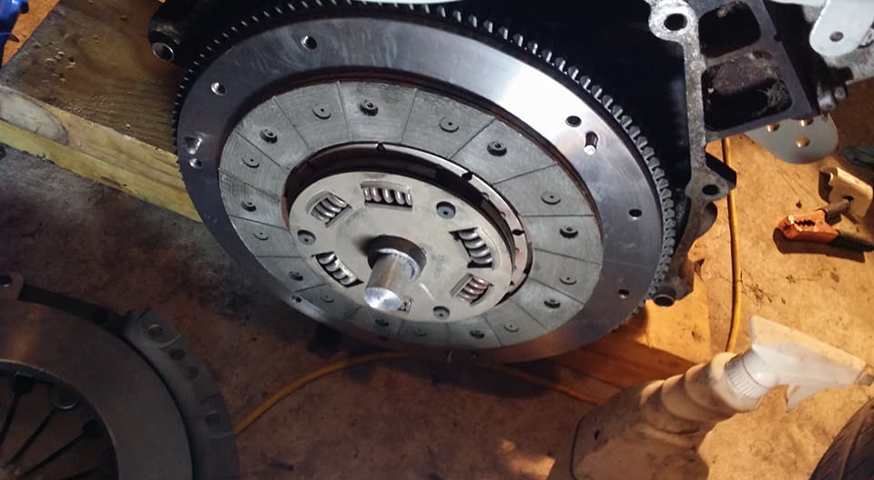
then i threw the pressure plate on.
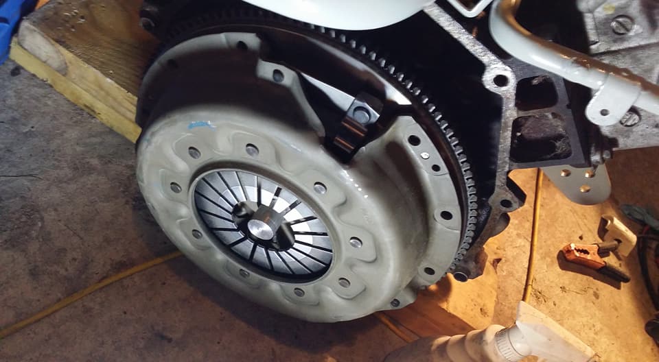
torqued down all the bolts to 25ish ftlbs (probably ended up being more like 35 lol)
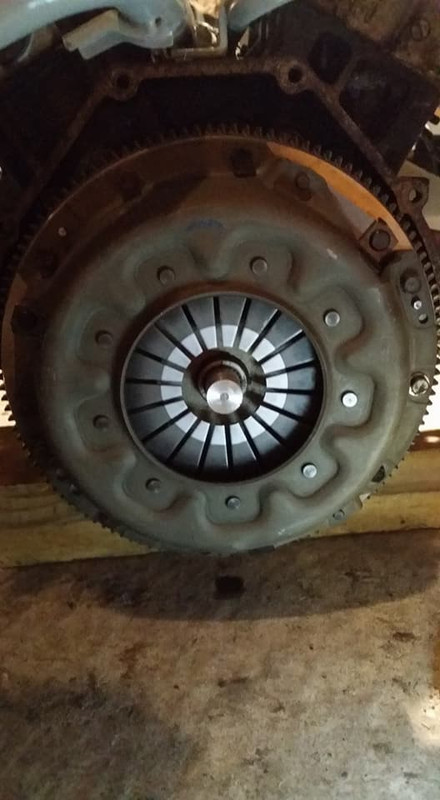
then pulled to tool out. i was gonna make a joke about how easily it slid out of the hole but im just gonna let yall insert your own.
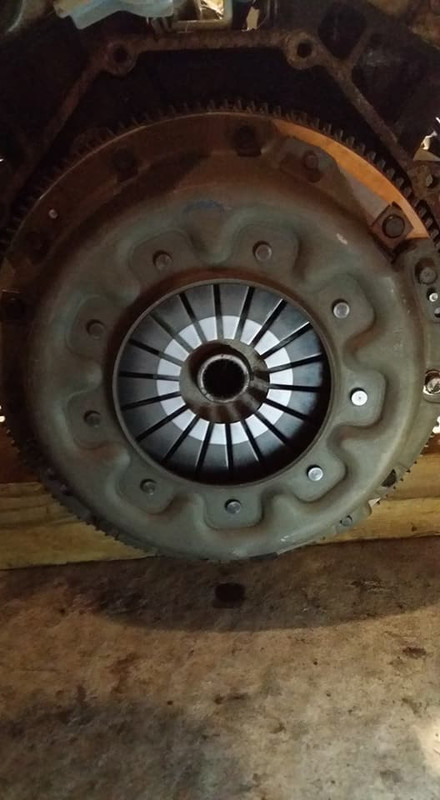
then i threw the trans back on (with the sandwich plate, fortunately its a two piece sandwich plate which my vg33 did not have and i had to take my flywheel off just to put that on so i checked that i could put that on with all this on before i started lol)
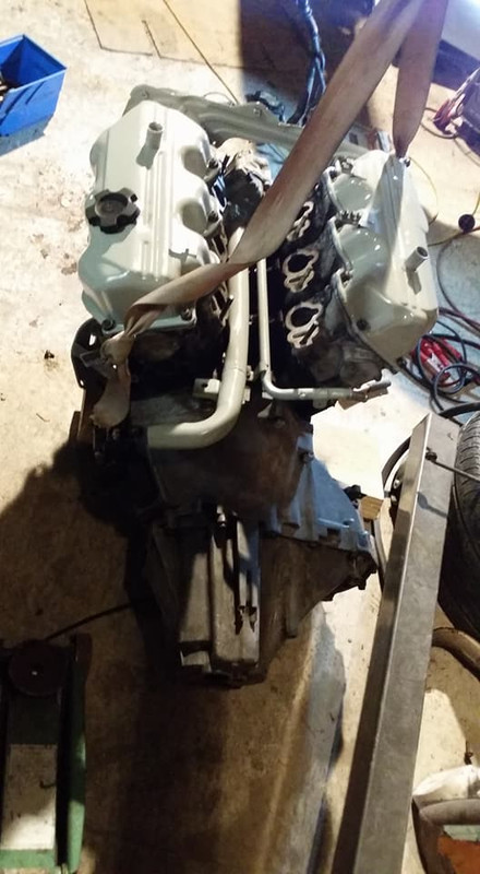
after i came back home later i got back to working on the starter, the commutator bars looked really uneven so i threw the starter on my lathe first, turned them all down flat (picked the chips out from in between the bars because for some reason they got like pressed into there...) then i sanded them.
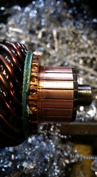
the brushes have springs that push them into the commutator bars to keep solid contact. you need to keep these springs compressed in order to get the rotor back into the permanent magnet case. i just used pieces of welding wire for this.
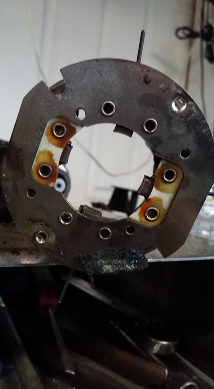
they are pretty easy to just wedge in between the springs themselves and the back of the brush guides.
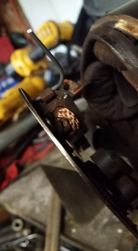
then you just slide it back in and put everything else back together.
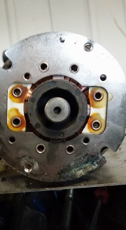
after i did this i filed the brushes down a bit so they could wear in with the new shape of the commutator bars. im hoping this has fixed the issue with the starter not turning properly, i will find out later when i bring it back over to the garage. next up is fuel stuff.
then i threw the pressure plate on.
torqued down all the bolts to 25ish ftlbs (probably ended up being more like 35 lol)
then pulled to tool out. i was gonna make a joke about how easily it slid out of the hole but im just gonna let yall insert your own.
then i threw the trans back on (with the sandwich plate, fortunately its a two piece sandwich plate which my vg33 did not have and i had to take my flywheel off just to put that on so i checked that i could put that on with all this on before i started lol)
after i came back home later i got back to working on the starter, the commutator bars looked really uneven so i threw the starter on my lathe first, turned them all down flat (picked the chips out from in between the bars because for some reason they got like pressed into there...) then i sanded them.
the brushes have springs that push them into the commutator bars to keep solid contact. you need to keep these springs compressed in order to get the rotor back into the permanent magnet case. i just used pieces of welding wire for this.
they are pretty easy to just wedge in between the springs themselves and the back of the brush guides.
then you just slide it back in and put everything else back together.
after i did this i filed the brushes down a bit so they could wear in with the new shape of the commutator bars. im hoping this has fixed the issue with the starter not turning properly, i will find out later when i bring it back over to the garage. next up is fuel stuff.
Last edited by Nate Boslet; 05-18-2018 at 10:30 AM.
06-17-2017, 01:01 AM
#119
Member
Thread Starter
Join Date: Oct 2016
Posts: 284
so i installed new orings and painted my fuel rails........ not much else goin on lol im supposed to be finishing the bay up tomorrow so ill make a post about that tomorrow night or sunday morning.
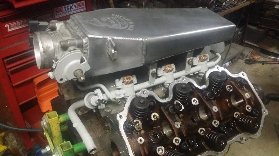
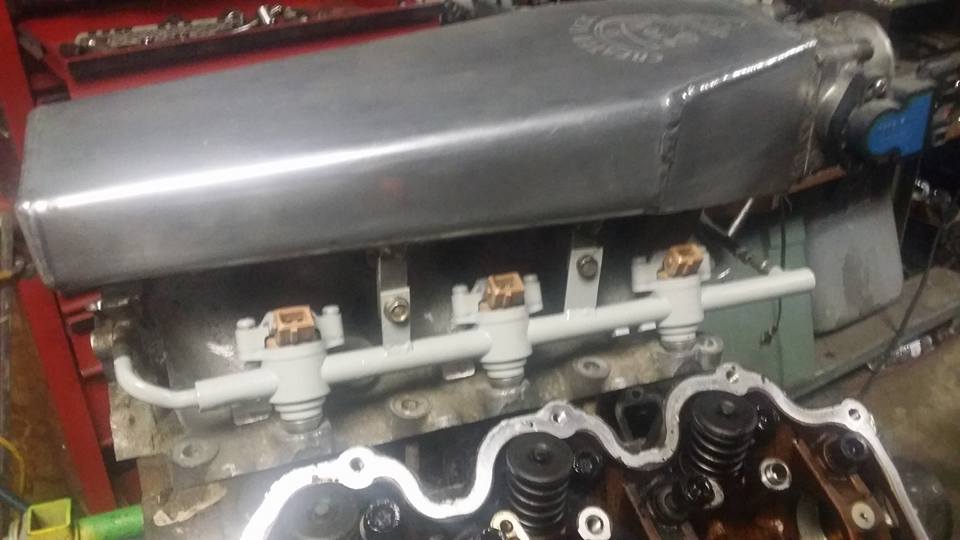
i didnt intend on waiting this long to have the bay painted but ive been checking on the poly in my mounts every few days and they are still not fully cured yet. the transmission mount is probably 80% or so but the front engine mount is maybe 50 lol hoping i might be able to speed the process up a bit i drilled 12 small holes in the body of the mount, 4 rows of 3, each hole is 1/8th of an inch. idk by how much this will speed up curing but i cant imagine it wouldnt help at all and there is virtually no structural impact from the holes. anyway once the bay is done being painted the car should be back together, then ill just have to finish the exhaust, slap some new fuel hoses on and see if she will run.
i didnt intend on waiting this long to have the bay painted but ive been checking on the poly in my mounts every few days and they are still not fully cured yet. the transmission mount is probably 80% or so but the front engine mount is maybe 50 lol hoping i might be able to speed the process up a bit i drilled 12 small holes in the body of the mount, 4 rows of 3, each hole is 1/8th of an inch. idk by how much this will speed up curing but i cant imagine it wouldnt help at all and there is virtually no structural impact from the holes. anyway once the bay is done being painted the car should be back together, then ill just have to finish the exhaust, slap some new fuel hoses on and see if she will run.
Last edited by Nate Boslet; 05-18-2018 at 10:31 AM.
06-18-2017, 12:48 PM
#120
Member
Thread Starter
Join Date: Oct 2016
Posts: 284
THE ENGINE BAY PAINTING IS FINISHED!!!*
*mostly
heres how my paint job began life-
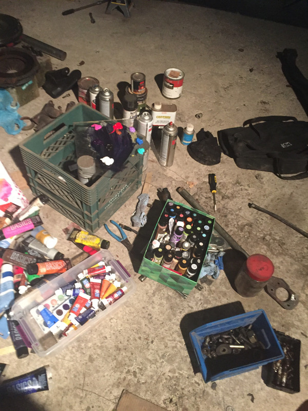
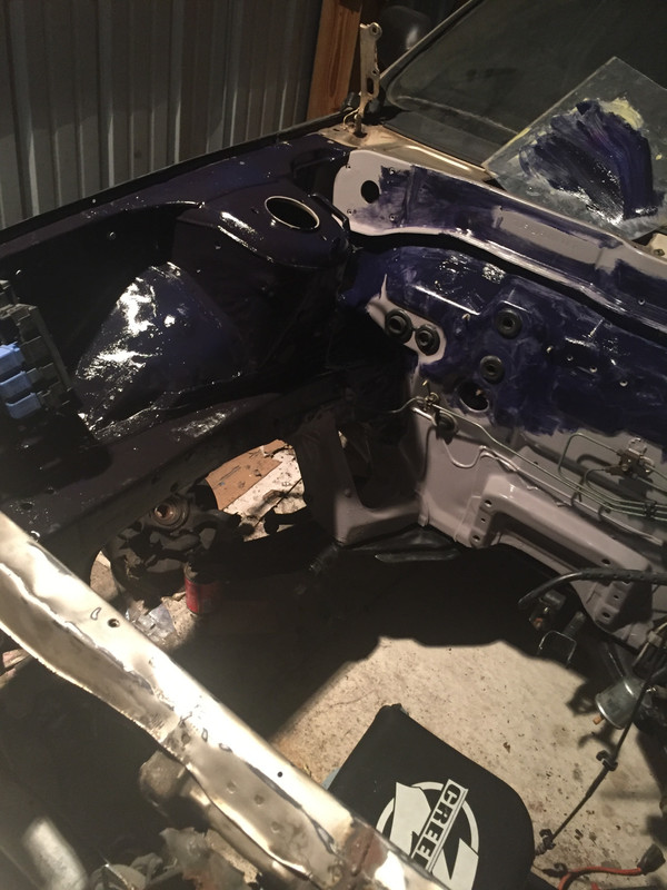
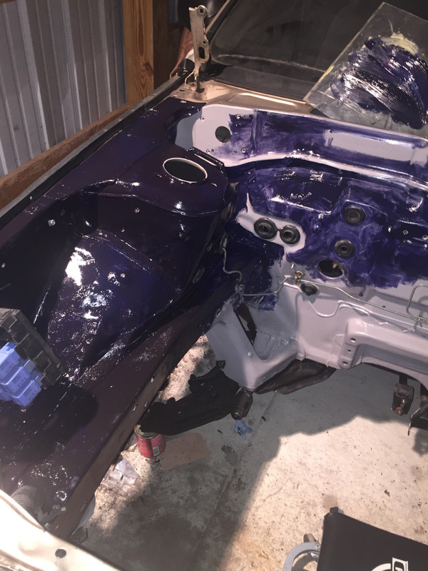
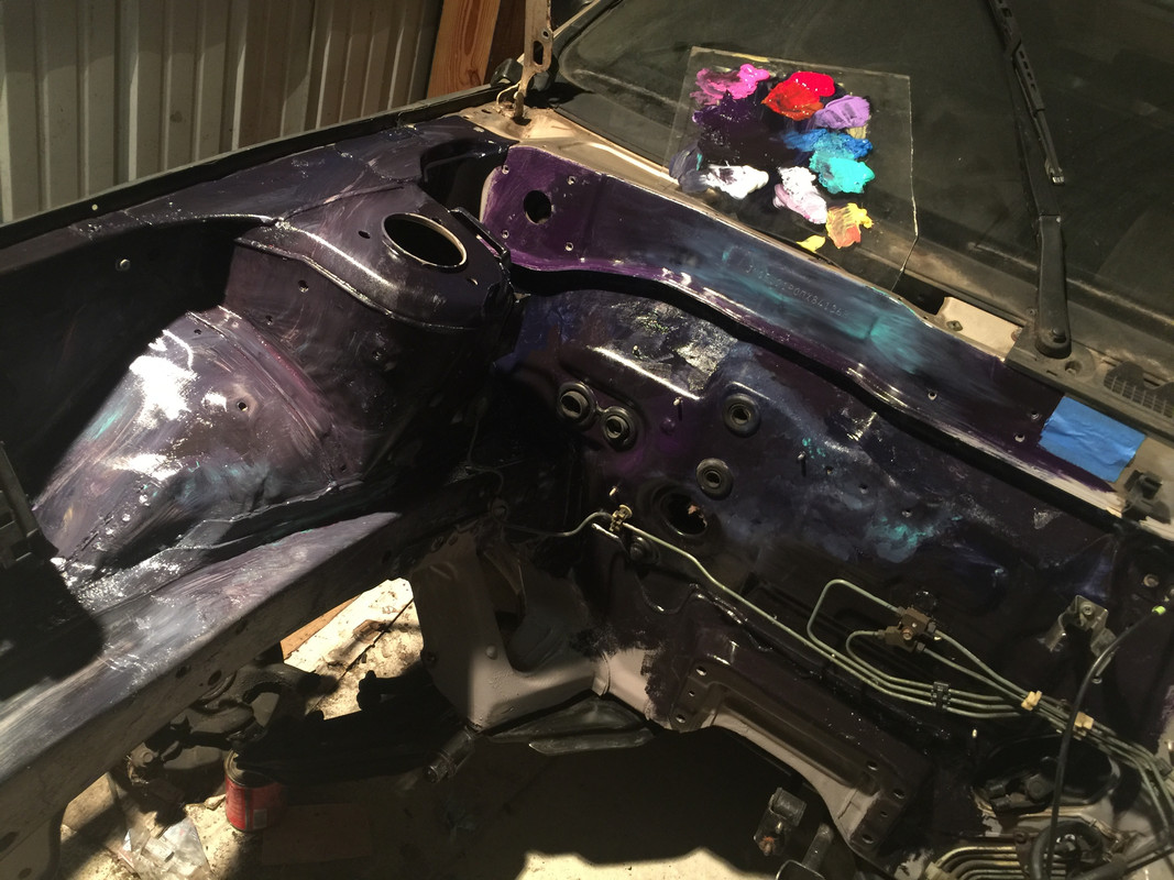
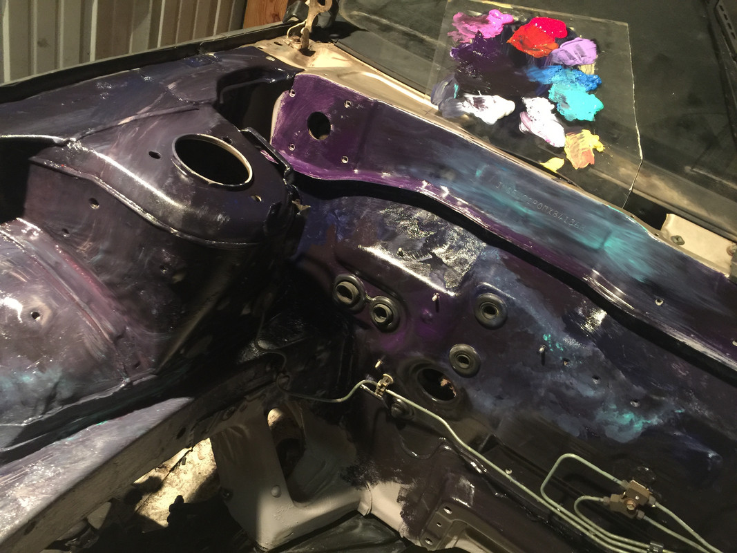
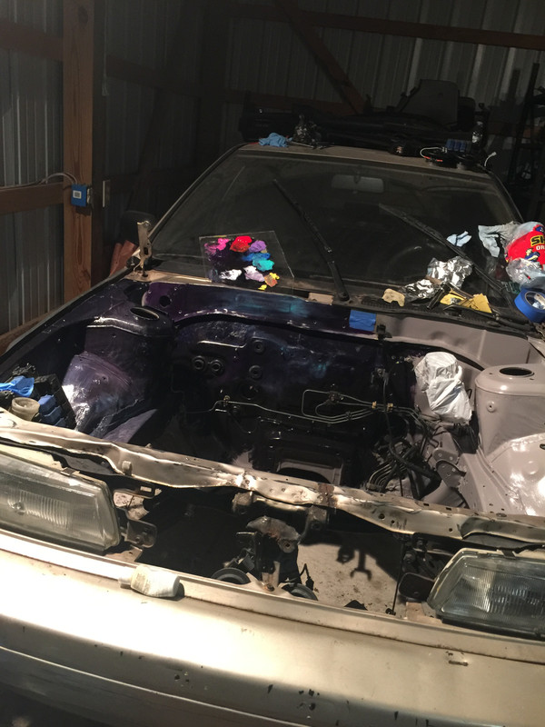
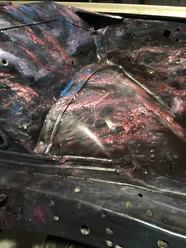
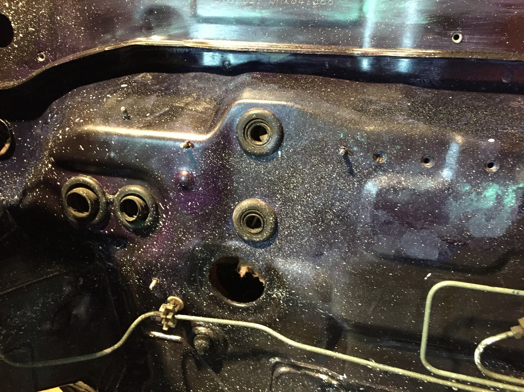
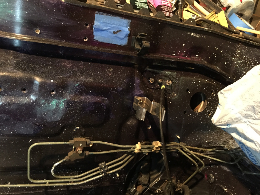
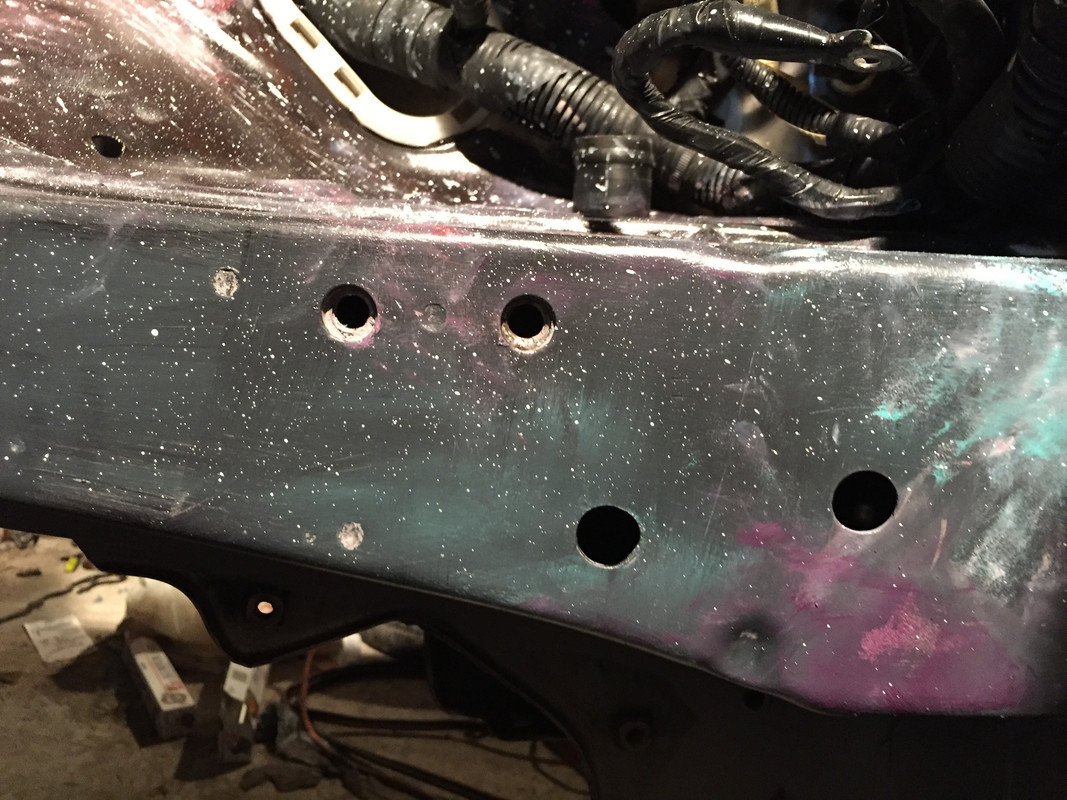
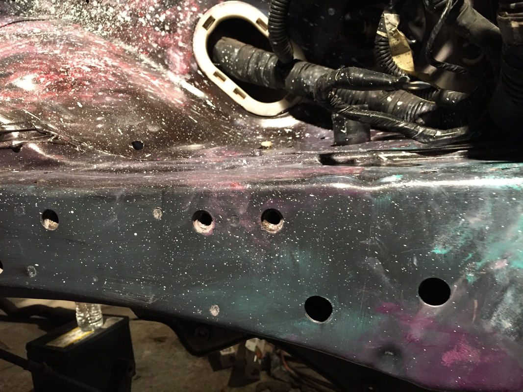
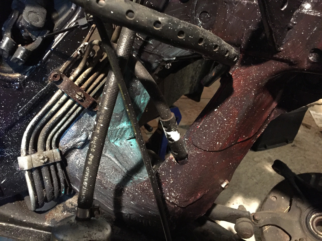
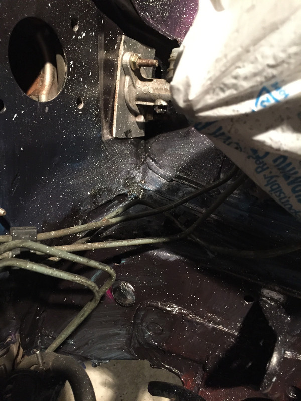
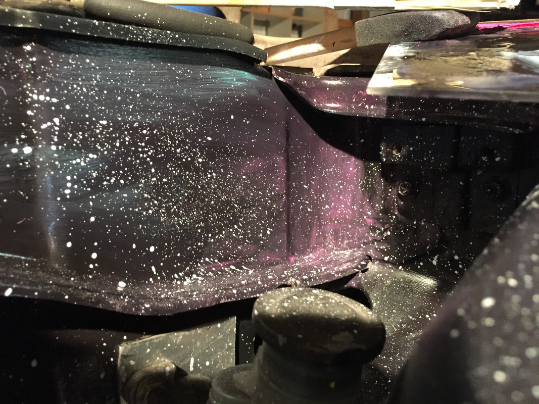
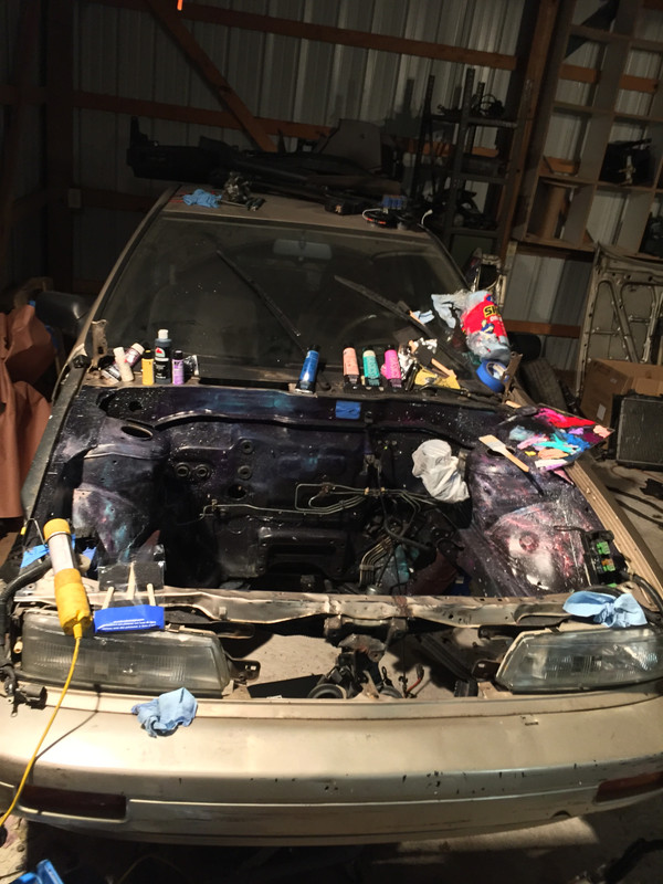
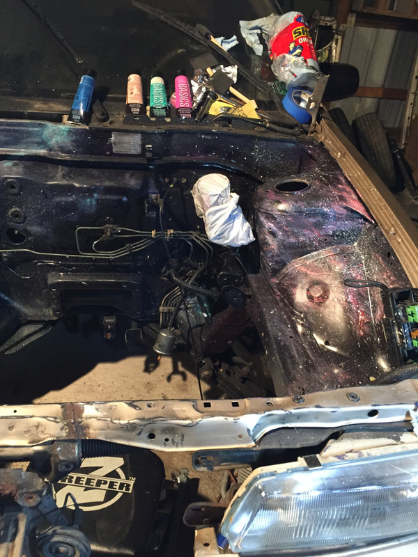
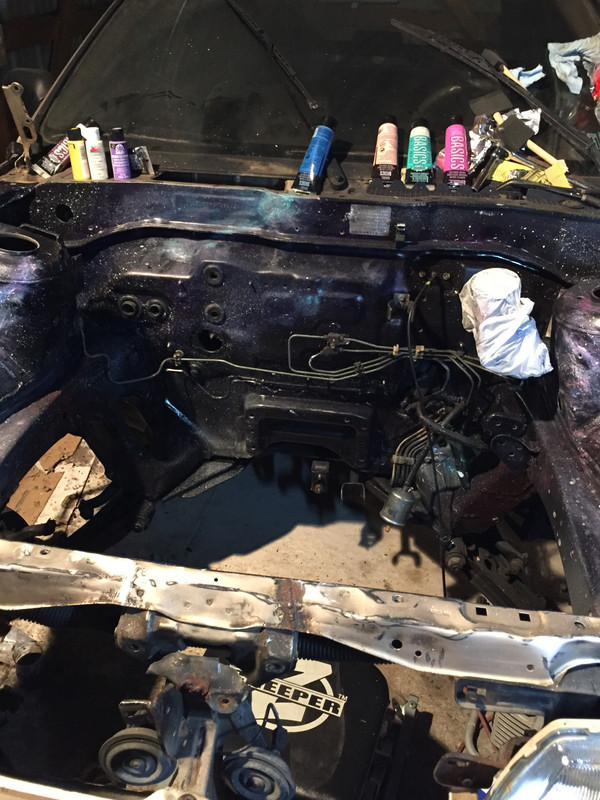
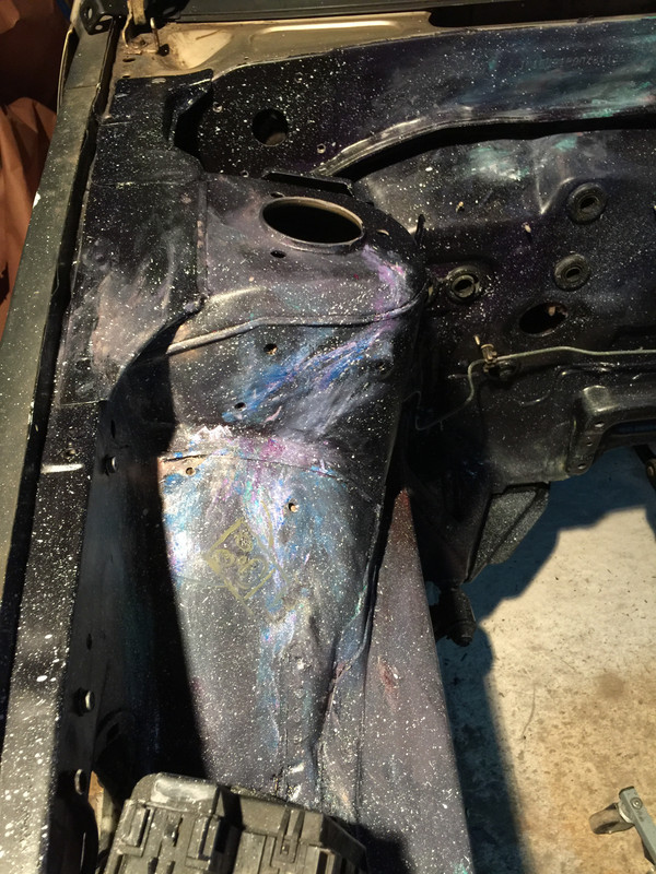
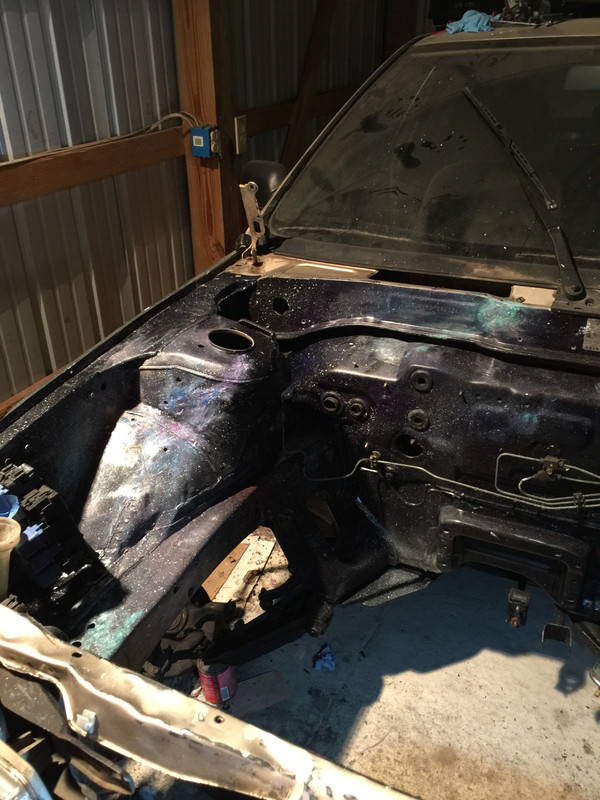
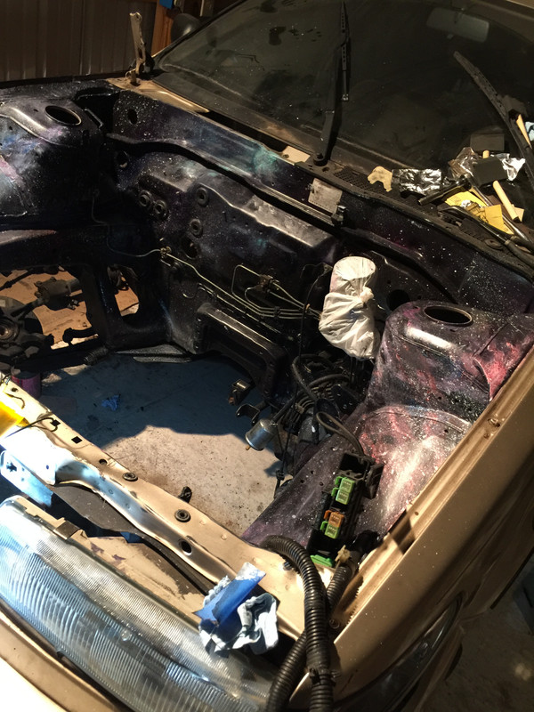
not much to say about it other than holy ******ing **** ****** ** ***** ******* **** ****** ****** ********* **** *** ***** *** ******** *** **** and a side of ****
going back over today with my friend to complete the other little detail areas and possibly begin clear coating. later in the week ill begin reassembly and get an idea of how the finished car will actually look. im super excited lol
*mostly
heres how my paint job began life-
not much to say about it other than holy ******ing **** ****** ** ***** ******* **** ****** ****** ********* **** *** ***** *** ******** *** **** and a side of ****
going back over today with my friend to complete the other little detail areas and possibly begin clear coating. later in the week ill begin reassembly and get an idea of how the finished car will actually look. im super excited lol
Last edited by Nate Boslet; 05-18-2018 at 10:33 AM.

