MAINTENANCE and MECHANICAL Information- Don't Post Questions Here! (UPDATED)
 10-22-2001, 02:23 PM
#1
Mod her. Ate her.

Thread Starter
iTrader: (19)
Join Date: May 2002
Location: Martinsburg, WV
Posts: 9,827
MAINTENANCE and MECHANICAL Information- Don't Post Questions Here! (UPDATED)
Do Not Post Questions In This Thread!
Note:
To search this thread use the "search this thread" box in the upper right corner.
Fault Indicator Light Diagnosis (If "trouble" lights are on, read here first!!!)
LINK to 4th Gen How-To Summary!
LINK to Exhaust Information Thread (With Sound Clips)!
Repair Manual Online The autozone "manual" has many general how to's. Check and see if the how to is in here before making random threads.
60k Service
I know some of the links do not work, check the NEW how to link posted above for more information/new links!!!!!
Links to get started:
Credit: SXN
Engine
How to replace a Water Pump
http://www.vqpower.com/v2/readarticle.php?article_id=68
How to Analyize/Reset a Check Engine Light http://forums.maxima.org/oldthread.php?t=104931
How to Change Knock Sensor http://www.motorvate.ca/mvp.php/507
How to Change Engine Oil http://www.motorvate.ca/mvp.php/511
How to Change Engine Coolant http://www.motorvate.ca/mvp.php/502
How to Replace Power Steering Fluid http://www.motorvate.ca/mvp.php/702
How to Replace Fuel Pump
http://www.vqpower.com/v2/readarticle.php?article_id=96
How to Install a Basic UDP http://www.greghome.com/Greg's%20Garage/1999%20Nissan%20Maxima%20SE/Underdrive%20Pulley.htm
How to replace drive belts
http://www.greghome.com/images/Maxim...DriveBelts.jpg
How to Change Your Spark Plugs http://www.vqpower.com/v2/readarticle.php?article_id=45
How to Install a Mevi (Middle Eastern Variable Intake)http://www.vqpower.com/v2/readarticle.php?article_id=50
How to Change Clutch Slave Cylinder Hose http://www.vqpower.com/v2/readarticle.php?article_id=62
How to Remove/ Replace Your Power Steering http://www.motorvate.ca/mvp.php/702
How to Examine/Change Your Fuel Filter
http://www.vqpower.com/v2/readarticle.php?article_id=97
How to Trouble Shoot TPS (Throttle Position Sensor) Problems
http://www.vqpower.com/v2/readarticle.php?article_id=95
How to Re-Grease Starter http://www.motorvate.ca/mvp.php/516
How to Wire Your Cooling Fans For Manual Use http://jime.f-sw.com/fan.html
How to Install a Pathfinder Throttle Body
http://www.vqpower.com/v2/readarticl...article_id=147
How to install a stillen SC - http://www.vqpower.com/v2/readarticle.php?article_id=73
How to change fuel injectors http://www.vqpower.com/v2/readarticl...article_id=153
How to change Thermostat - http://www.vqpower.com/v2/readarticl...article_id=150
How to change timing chain tensioner
http://forums.maxima.org/showthread.php?t=134338
http://forums.maxima.org/oldthread.php?t=527500 - update
Drivetrain/ Transmission
How To change Motor Mounts http://www.vqpower.com/v2/readarticl...article_id=151
How to cheaply improve manual shifter feeling http://forums.maxima.org/oldthread.php?t=331517
How to Fix CV Joints http://www.motorvate.ca/mvp.php/401
How to Change/Replace Your Clutch http://www.motorvate.ca/mvp.php/801
How to Remove/Rebuild Your Tranny (5 Speed) http://www.motorvate.ca/mvp.php/805
How to Install a Short Throw Shifter http://www.vbxmaxima.8m.com/shifter.html
How to Convert Your Auto to 5 Speed (pretty serious and involved) http://www.vqpower.com/v2/readarticle.php?article_id=44
How to Install a Valve Body http://www.vqpower.com/v2/readarticle.php?article_id=60
Electrical
How to activate the Low Washer Fluid light (for cars without cold/deluxe packages) http://www.vqpower.com/v2/readarticl...article_id=113
How to change alternator http://www.motorvate.ca/mvp.php/500
How to Fix Starter Noise http://www.motorvate.ca/mvp.php/516
How to make your cruise control always ready http://www.vqpower.com/v2/readarticle.php?article_id=28
How to Remove Your Top Speed Limiter
http://www.vqpower.com/v2/readarticle.php?article_id=38
How to Make Your Sun Roof One Touch Open http://www.vqpower.com/v2/readarticle.php?article_id=40
How to Make Your Wipers Variable Intermittent http://www.vqpower.com/v2/readarticle.php?article_id=42
Last edited by Kevlo911; 06-23-2009 at 09:40 AM.
 10-24-2001, 07:58 AM
#2
Supporting Maxima.org Member
Join Date: Oct 2000
Posts: 9,159
Can I add ABS to my car?
10-31-2001, 11:37 AM
#3
Supporting Maxima.org Member
Join Date: Oct 2000
Posts: 9,159
Can I put a Fifth Gen (2000-2001/3.0) engine in my fourth Gen?
Yes. The fifth Gen engine is the same basic design as the fourth gen engine. It is rated at 222 HP compared with the fourth gens 190, but makes basically the same power until after 5000 RPM. Some of this increase comes from slightly improved exhaust, if you put an aftermarket exhaust on your car it will be much better than the fifth gen exhaust. The Majority of the gains come from the intake manifold. The fifth Gen intake manifold is a dual runner design, it switches to shorter runners above 5000 Rpm for improved high RPM power. In the fourth Gen power drops off quickly after about 5500 RPM due to the long intake runners. Any engine swap on a Nissan is going to be a huge undertaking and very expensive. If you are not up to the task, it may more cost effective to bolt-on or boost your 4th Gen. There are about 2.5 Bazillion threads on this, so try the Google Search.
How about a fifth Gen intake manifold?
Yes. Also consider that there is a fourth gen Variable intake Manifold available, if you can find one. It is not a true dual runner design like the fifth gen and will not give your engine the same increase over 5000 RPM that a fifth gen has, but it still is a great improvement over the stock intake manifold. Putting a fifth gen intake manifold on a fourth gen involves replacing pretty much everything from the top of the head up, a huge undertaking. There are many threads on this. Use the Google Search for more info.
Can I put the fifth Gen 3.5 engine in my fourth Gen?
Yes- but this is a huge and very expensive undertaking for many reasons. It may be cheaper to turbocharge or supercharge your 3.0 engine. There are many threads on this- Google Search is your friend.
http://forums.maxima.org/all-motor/4...swap-info.html
Look at that for more information.
Can I use the turbocharged engine or turbo parts from a 300zx?
No.
http://forums.maxima.org/oldthread.php?threadid=66787
http://forums.maxima.org/oldthread.php?threadid=43306
http://forums.maxima.org/oldthread.php?threadid=3010
http://forums.maxima.org/oldthread.php?threadid=61393
Can I put 300zx headers on a Maxima?
No.
http://forums.maxima.org/oldthread.php?threadid=75492
How about port and polish then?
This is a waste of time and energy.
http://forums.maxima.org/oldthread.php?threadid=33112
http://forums.maxima.org/oldthread.php?threadid=89247
Should I buy the Tornado Air fuel saver?
NO!
http://forums.maxima.org/oldthread.php?threadid=36255
How about the Electrice Supercharger?
NO!
http://forums.maxima.org/oldthread.php?threadid=100321
http://forums.maxima.org/oldthread.php?threadid=28016
http://forums.maxima.org/oldthread.php?threadid=1939
Theres a Throttle Body Bypass Coolant Mod on Ebay...should I?
This is the most ridiculous mod known to man, right along with the Tornado Fuel Saver.
1) Prepare to have a sticky throttle, that high idles at 1500 RPM alot. This is due to no coolant being passed through the TB and the high idle will kick in constantly.
"The Fast Idle Cam is operated by a Thermo-element mounted on the bottom of the Throttle Body. When you do the TB bypass mod, you are disabling the FIC. This is a silly mod except for a true race car, a car which is used only for racing." -Daniel B. Martin (http://forums.maxima.org/showpost.ph...9&postcount=43)
2) I felt zero difference in performance when I did it before. Whoever claims it adds 6 HP or whatever figure is FOS.
3) When I did it before, it cost me about $2.00 worth of materials. If you are going to do this, you buy a 2 foot section of 3/8" hose, you can reuse the hose clamps, or buy new ones, and (optional) buy 3/8" rubber cappers to cap the throttle body coolant. To pay more then $5 without shipping is completely highway robbery.
http://forums.maxima.org/oldthread.p...ghlight=bypass
What are all these 20+ HP chips I see on ebay?
They are timing advance resistors. Basically, it tells your ecu that your intake is recieving colder air.
----Do they work?
NO. The ECU only uses the air temp sensor as a reference to ensure that all it's primary readings are within range. Changing this resistance will not get any HP gains.
Don't even bother with them.[/QUOTE]
[QUOTE=ericdwong;662886]There seems to be a problem with the 5 speed 4 gen. Maxima's transmissions. Namely 95-97ish models with around 60,000 miles on them. A common problem is the differential bearings have failed. Seems to be that Nissan/whoever built the tranny did not bother to properly shim the preload of the differential bearings. Tell tale signs of differential bearing failure include:
-leaking seals
-metal shavings in transmission fluid
-play in the CV axle where it enters the transmission
-grinding/whining noises when the car is in motion
You may also have the problem and not show any signs of it. My car did not show any of the above signs, until I opened my transmission for a different project and discovered it. Simply changing the seals is not the answer either, as they will just get stretched again.
The repair bill of this item is very expensive due to labor. Probabaly $800 to well over $1000 for labor charges, to change the $35 bearing(s). The transmission must be taken off the car and disassembled to service. If having somebody else do the service, BE SURE THEY PROPERLY SHIM THE NEW BEARINGS OR ELSE THE PROBLEM WILL CROP UP AGAIN!!! Many times the repair shop will just say "screw it" and not shim the new bearings. This is a great way to put a patch on the wound that will just break again.
"Can I do it myself?" Sure. Just prepared to remove and diassemble the transmission from the car. You will also need a precision dial gauge indicator to properly shim the bearings, a factory service manual, and you will need probably a week to wait for parts to come in. Definately not a job for the amature mechanic.
There is nothing you can do short of crossing your fingers to prevent this from happening, it is a manufacturing defect. Hopefully you will catch it before the 60,000 mile powertrain warranty is up.
references:
http://forums.maxima.org/4th-generat...w.motorvate.ca
http://forums.maxima.org/showthread....t=transmission
http://forums.maxima.org/showthread.php?t=66782
http://forums.maxima.org/showthread.php?t=54048
http://forums.maxima.org/showthread.php?t=31530
http://forums.maxima.org/showthread.php?t=29857
Last edited by Kevlo911; 06-23-2009 at 09:41 AM.
02-14-2002, 04:07 PM
#4
Senior Member

Join Date: Aug 2000
Posts: 2,530
Stock Flywheel weight and upgrading
For those interested in objective flywheel data I put together some of my old posts: Number one, the 4 gen flywheel is NOT lightenable like the 3 gens are. The reason for this is because, our flywheel is a 2 piece set. The secondary ring gear is what the crankshaft position sensor reads. I got a call back from my machine shop who was gonna lighten my flywheel and they told me this. They unbolted the secondary ring gear from the main ring gear and they tell me that there really isnt any place to lighten the OE flywheel, and even if there was, there wouldnt be enough meat to remove to yield a siginificant difference. Now that I think about it, I dont think anybody in the 4th or 5th gen's have had their OE flywheel chopped. Only 3rd gen's including Jeff92se and Matt93gxe because their designs are different.
The formula according to Phuong for calculating flywheel weight reduction is:
1/2 FW weight * [(flywheel radius x gear x final drive)/(tire radius)]^2
On my 4th generaion, I am running 225 50 16s. I did the conversions and plugged in the formula. BTW, the 4th gen's M/T gearing is like this according to my FSM on page MT40. Ratios: 1st (3.285), 2nd (1.850), 3rd (1.272), 4th (0.954), 5th(0.795), Reverse (3.428) and Final gear is (3.823). For those of you who want to plug the formula in easier in 1st gear it will be 1/2 flywheel weight * [(120mm*3.285x3.823)/314.96mm]^2.
I got my OE flywheel weighed at the local post office, and they confirmed it was calibrated to spec, etc. The stock flywheel WITHOUT the secondary ring gear or bolts weighs 18 pounds, 7 ounces. I used my own postal scale and found the bolts and secondary ring gear to be 1 pound, 10.7 ounces. Add these two together and the total rotating mass (not including pressure plate) is 20 pounds, 1.7 ounce. Since the secondary has to be used with either flywheel the difference in weight is roughly 13 pounds, 7 ounces or 13.4375 pounds. from the Unorthodox Racing flywheel which claims a net weight of 5 pounds. Plug this number into our favorite equation up above and the weight reduction in first gear is equivalent of removing 153.8 pounds of static weight.
The other two options are the Mueller/Stillen Flywheel and the fidanza. The fidanza or stillen wheels shouldnt suffer any sorta drivabilty problem like the U/R at 5 pounds unit might. One thing about a lighter flywheel is that although it reduces rotating mass, it may produce a bog effect at the drag strip off the line.
02-16-2002, 12:26 PM
#5
Senior Member
Join Date: Aug 2000
Posts: 2,530
Whats this oil leak near my oil pan?
Chances are it is the Oil Pressure Sender unit, which is a 1" in diameter funky looking switch that has an electrical connector on it. The OEM ones are notorious for failing and/or leaking, even as low as 20K miles. Anyway to change it out is very easy. You have to use a 1 1/16" DEEP WELL socket. 6 or 12 point should work, but I used 6 point. Unclip the electrical connector, and simply remove the switch using the wrench stated above, while having the new switch ready. Draining the oil is not necessary, but a few drops will come out. Prepare to catch the spill using shop towels/rags. Put in the new switch and snug it up. After, I cleaned my entire area up using brake cleaner. Check it periodically to make sure it isnt leaking again and make sure your OIL light does not come on in the dash. So far, mine has been OK.
Daniel B Martin suggest NOT to use the OEM switch. I got a Wells PS159 switch for about $6 from a local auto parts store.
Daniel B Martin suggest NOT to use the OEM switch. I got a Wells PS159 switch for about $6 from a local auto parts store.
02-16-2002, 12:29 PM
#6
Senior Member
Join Date: Aug 2000
Posts: 2,530
Can I install an Optima Battery in my car? What are the benefits?
You can install an Optima battery in your car with very little modification. I have a Yellow top in my car. The OEM cables are long enough to reach the top terminals of an Optima Battery. The only modification you must do, is find some sort of spacer to put beneath the battery in the battery tray. I used scraps of 1/4" MDF. This is because the Optima Battery is shorter in height then the OEM battery. That plastic box that the OE battery comes with is not used. The OEM battery tie down and battery clamps will work. If your new Optima's battery has side terminals, I suggest double grounding the negative side by going to your local car parts store and buying a 24" 4 gauge side terminal battery clamp, and a side terminal for the battery. I put my second ground from the Optima's side terminal to the transmission mount's through bolt, although I had to slightly enlarge the battery cable's connector with a dremel.
The advantages of using a Yellow top are its deep cycle properties, mainly for high powered car stereo use.
For more info go to:
www.optimabatteries.com
The advantages of using a Yellow top are its deep cycle properties, mainly for high powered car stereo use.
For more info go to:
www.optimabatteries.com
02-17-2002, 02:59 PM
#7
Senior Member
Join Date: Aug 2000
Posts: 2,530
My 5 speed transmission is leaking near the CV inputs
There seems to be a problem with the 5 speed 4 gen. Maxima's transmissions. Namely 95-97ish models with around 60,000 miles on them. A common problem is the differential bearings have failed. Seems to be that Nissan/whoever built the tranny did not bother to properly shim the preload of the differential bearings. Tell tale signs of differential bearing failure include:
-leaking seals
-metal shavings in transmission fluid
-play in the CV axle where it enters the transmission
-grinding/whining noises when the car is in motion
You may also have the problem and not show any signs of it. My car did not show any of the above signs, until I opened my transmission for a different project and discovered it. Simply changing the seals is not the answer either, as they will just get stretched again.
The repair bill of this item is very expensive due to labor. Probabaly $800 to well over $1000 for labor charges, to change the $35 bearing(s). The transmission must be taken off the car and disassembled to service. If having somebody else do the service, BE SURE THEY PROPERLY SHIM THE NEW BEARINGS OR ELSE THE PROBLEM WILL CROP UP AGAIN!!! Many times the repair shop will just say "screw it" and not shim the new bearings. This is a great way to put a patch on the wound that will just break again.
"Can I do it myself?" Sure. Just prepared to remove and diassemble the transmission from the car. You will also need a precision dial gauge indicator to properly shim the bearings, a factory service manual, and you will need probably a week to wait for parts to come in. Definately not a job for the amature mechanic.
There is nothing you can do short of crossing your fingers to prevent this from happening, it is a manufacturing defect. Hopefully you will catch it before the 60,000 mile powertrain warranty is up.
references:
www.motorvate.ca
http://forums.maxima.org/showthread....t=transmission
http://forums.maxima.org/showthread....t=transmission
http://forums.maxima.org/showthread....t=transmission
http://forums.maxima.org/showthread....ission+bearing
http://forums.maxima.org/showthread....ission+bearing
02-26-2002, 11:13 AM
#8
How do I get rid of my top speed limiter?
Only some 4th gen GXEs are limited. If you have an SE or GLE, you have no limiter. The only way to tell if your GXE has one is to hit the road and see how fast you can go. If you have a limiter, your fuel will be cut off and the engine will drop to idle speed at about 115mph.
original thread
Credit: mzmtg & SprintMax
Write up with pics: http://www.sprintmax.com/tails/bensecumod.htm
EDIT:There is no doubt when you have hit the speed limiter. It is not subtle. In the following link, listen to the sound. The accelerator is floored for the entire duration of this clip. The engine cuts of suddenly and the RPMs drop. Actually, at the last second of the clip, you can see the fuel come back on and the RPM start to climb. If your car just eases up to a speed and stops accelerating, you dont have a limiter, your car is just topped out.
Right click, save as:
http://www.vqpower.com/vids/DSCN0336.avi
Disclaimer: The driving in this clip was conducted on a closed course by a professional driver. Do not attempt. And no comments on my slow azz car.
Last edited by Kevlo911; 02-09-2008 at 07:23 AM.
02-27-2002, 09:46 AM
#9
Senior Member
Join Date: Aug 2000
Posts: 2,530
I want to install a Quaife differential- what are its benefits, can I do it myself?
NOTE: This part is no longer available in the United States!
Quaife differential is a automatic torque biasing differential, similar to a limited slip.
http://www.quaifeamerica.com
"The Quaife unit is not only the first aftermarket differential available for the Maxima and I30, it is arguably the best design in production for any car. Its all-gear design does what a typical limited slip differential is supposed to do, just a lot better, under any circumstances and for more miles. The Quaife differential makes your car accelerate quicker and corner faster by simply getting more power to the ground.
The Quaife Differential powers both drive wheels under nearly all conditions, instead of just one. With the Maxima's open differential, a lot of precious power is wasted during wheelspin (of one wheel) under acceleration. This happens because the open differential shifts power to the wheel with less grip. The Quaife does the opposite by sensing which wheel has the better grip, and biasing power to that wheel. This happens smoothly and constantly, without ever completely removing power from the other wheel.
The Quaife provides a significant advantage in any racing situation:
� In straight-line drag racing, torque is biased in a close to ideal 50/50 power split to both drive wheels, resulting in essentially twice the grip of an ordinary differential.
� In autocross or road racing, the Quaife biases power to the outside wheel while accelerating out of a turn, reducing inside-wheel spin. This allows the driver to begin accelerating earlier, exiting the corner at a higher speed.
The Quaife also controls loss of traction when the front wheels are on slippery surfaces like ice or mud, providing the appropriate constant and infinitely variable drive. Power is transferred automatically without the use of normal friction pads or plates seen in other limited-slip designs. The Quaife is extremely strong and durable and since it is gear operated, there are no plates or clutches that can wear out and need costly replacement.
Every Quaife ATB Differential comes with something else others don't have: a Limited Lifetime Warranty. This warranty applies even when raced! "
User's reactions:
http://forums.maxima.org/showthread.php?t=60646
http://forums.maxima.org/showthread.php?t=59267
http://forums.maxima.org/showthread.php?t=57425
http://forums.maxima.org/showthread.php?t=57068
Great so what does it look like?


OK, so how do I install it?
You'll need the minimum of these parts.
1. bearings you need 2 of them, 38440-96E00
2. Nissan part #32701-03E01 (speedometer drive gear)
3. differential seals #s are 38342-81X01 and 38342-81x00. Yes they are different, not sure what the input or gear selector seals are.
4. shims
You'll also need a Factory Service Manual, and a precision dial gauge that can read into the 1/1000 of an inch.
Instructions for canadian maxima 5speed rebuild can be found at: www.motorvate.ca The extra step is just to transfer the ring gear from the included differential to the quaife
also the pics are a tad different- the canadian maxima's had LSD already, where ours had open differentials. You can either use the existing speedeometer gear, by cutting/pressing the existing bearing, or buy a new one. I just bought a new one.
Make sure they set the bearing preload and use the gear fluid. Make sure there.s no silver, milky, or dark stuff in there. Use a magnet to see if there are any shavings. Oh yea, and make sure its 75-w90 GL4 gear oil. I used Amsoil synthetic 75w90 with excellent results in all temperatures.
Regarding the shims, what happens is you have to reassemble the transmission without the shims in place. then make the differential assembly move by pushing on it, and measure this movement using a dial gauge precision meter then, using the FSM's table reference, you will know what size of shim to order. You then must take apart the tranny again and put in the shims.
While you're at it, I think it is a good idea to check the shims of the input shaft as well, since I recently discovered that some of the transmissions have the exact same shims in them and were improperly shimmed. To do this, remove the shims of the input shaft and do the same process as the differential. Then using the FSM table and a micrometer, see if the shims in there are the correct ones. If not, order the correct ones. This step is real easy.
When you put the seals in, grease around the outside lip and dont drive them in too far. Also do it while the (the shop will most likely know all of this, this is more towards the DIYer) tranny is out of the car, and DON'T drive the seales in too far like I did, or otherwise you'll get nothing but a humongous leak.
Lets see, a few things to look out for while reassembling that I screwed up, to make sure you won't screw up. Make sure the cleaner magnet is in place, make sure the shifter rods point the right way with their detents so the shifter will have a "click" action, make sure the reverse gear is in between the reverse engagement fork and not ontop of it. Also make sure a torque wrench is always used and I recommend loctite on every threaded bolt in and outside the transmission. Be sure to TEST the tranny by giving it a spin test in every gear to make sure that it works the way its supposed to. Other then that, reassembling the manual tranny isn't too bad.
Expect this project to take several days, many of it will be waiting for parts to arrive. While you're at it, its a great time to polyurethaneize your motor mounts, steam clean the inside, change the flywheel/clutch or any other project that may take several days.
EDIT- I've recently found out you can do this project very easily. You DO NOT have to take apart all the transmission internals to get to the differential. Open the case, remove the speedometer sensor, and then pull the main and input shaft up about 1/4" or so. Then the differential will slide right out!
Quaife differential is a automatic torque biasing differential, similar to a limited slip.
http://www.quaifeamerica.com
"The Quaife unit is not only the first aftermarket differential available for the Maxima and I30, it is arguably the best design in production for any car. Its all-gear design does what a typical limited slip differential is supposed to do, just a lot better, under any circumstances and for more miles. The Quaife differential makes your car accelerate quicker and corner faster by simply getting more power to the ground.
The Quaife Differential powers both drive wheels under nearly all conditions, instead of just one. With the Maxima's open differential, a lot of precious power is wasted during wheelspin (of one wheel) under acceleration. This happens because the open differential shifts power to the wheel with less grip. The Quaife does the opposite by sensing which wheel has the better grip, and biasing power to that wheel. This happens smoothly and constantly, without ever completely removing power from the other wheel.
The Quaife provides a significant advantage in any racing situation:
� In straight-line drag racing, torque is biased in a close to ideal 50/50 power split to both drive wheels, resulting in essentially twice the grip of an ordinary differential.
� In autocross or road racing, the Quaife biases power to the outside wheel while accelerating out of a turn, reducing inside-wheel spin. This allows the driver to begin accelerating earlier, exiting the corner at a higher speed.
The Quaife also controls loss of traction when the front wheels are on slippery surfaces like ice or mud, providing the appropriate constant and infinitely variable drive. Power is transferred automatically without the use of normal friction pads or plates seen in other limited-slip designs. The Quaife is extremely strong and durable and since it is gear operated, there are no plates or clutches that can wear out and need costly replacement.
Every Quaife ATB Differential comes with something else others don't have: a Limited Lifetime Warranty. This warranty applies even when raced! "
User's reactions:
http://forums.maxima.org/showthread.php?t=60646
http://forums.maxima.org/showthread.php?t=59267
http://forums.maxima.org/showthread.php?t=57425
http://forums.maxima.org/showthread.php?t=57068
Great so what does it look like?
OK, so how do I install it?
You'll need the minimum of these parts.
1. bearings you need 2 of them, 38440-96E00
2. Nissan part #32701-03E01 (speedometer drive gear)
3. differential seals #s are 38342-81X01 and 38342-81x00. Yes they are different, not sure what the input or gear selector seals are.
4. shims
You'll also need a Factory Service Manual, and a precision dial gauge that can read into the 1/1000 of an inch.
Instructions for canadian maxima 5speed rebuild can be found at: www.motorvate.ca The extra step is just to transfer the ring gear from the included differential to the quaife
also the pics are a tad different- the canadian maxima's had LSD already, where ours had open differentials. You can either use the existing speedeometer gear, by cutting/pressing the existing bearing, or buy a new one. I just bought a new one.
Make sure they set the bearing preload and use the gear fluid. Make sure there.s no silver, milky, or dark stuff in there. Use a magnet to see if there are any shavings. Oh yea, and make sure its 75-w90 GL4 gear oil. I used Amsoil synthetic 75w90 with excellent results in all temperatures.
Regarding the shims, what happens is you have to reassemble the transmission without the shims in place. then make the differential assembly move by pushing on it, and measure this movement using a dial gauge precision meter then, using the FSM's table reference, you will know what size of shim to order. You then must take apart the tranny again and put in the shims.
While you're at it, I think it is a good idea to check the shims of the input shaft as well, since I recently discovered that some of the transmissions have the exact same shims in them and were improperly shimmed. To do this, remove the shims of the input shaft and do the same process as the differential. Then using the FSM table and a micrometer, see if the shims in there are the correct ones. If not, order the correct ones. This step is real easy.
When you put the seals in, grease around the outside lip and dont drive them in too far. Also do it while the (the shop will most likely know all of this, this is more towards the DIYer) tranny is out of the car, and DON'T drive the seales in too far like I did, or otherwise you'll get nothing but a humongous leak.
Lets see, a few things to look out for while reassembling that I screwed up, to make sure you won't screw up. Make sure the cleaner magnet is in place, make sure the shifter rods point the right way with their detents so the shifter will have a "click" action, make sure the reverse gear is in between the reverse engagement fork and not ontop of it. Also make sure a torque wrench is always used and I recommend loctite on every threaded bolt in and outside the transmission. Be sure to TEST the tranny by giving it a spin test in every gear to make sure that it works the way its supposed to. Other then that, reassembling the manual tranny isn't too bad.
Expect this project to take several days, many of it will be waiting for parts to arrive. While you're at it, its a great time to polyurethaneize your motor mounts, steam clean the inside, change the flywheel/clutch or any other project that may take several days.
EDIT- I've recently found out you can do this project very easily. You DO NOT have to take apart all the transmission internals to get to the differential. Open the case, remove the speedometer sensor, and then pull the main and input shaft up about 1/4" or so. Then the differential will slide right out!
Last edited by Kevlo911; 02-09-2008 at 07:23 AM.
02-27-2002, 04:03 PM
#10
Senior Member
Join Date: Aug 2000
Posts: 2,530
Does this hose connect to anything?
...I was under the hood the other day and noticed a hose that is connected to nothing. Is this normal?
Yes this is normal. This hose is a breather hose that points down and is not connected to anything. Have no fear.
The hose is located near the large breather hose on the front valve cover. It appears to connected to the transmission at the bottom. It is a hard rubber hose that has it's open, upper end molded to face downward.
02-28-2002, 09:51 AM
#11
Senior Member
Join Date: Aug 2000
Posts: 2,530
My clutch pedal is too high/too low/wants to adjust itself...what can I do?
Get a flashlight and move back your seat. Get a 12 mm open ended wrench. Look above the clutch pedal and there is a threaded rod that also has ridges that run up and down the rod that goes into the fire wall and moves with the pedal. Find the 12 mm lock nut and loosen it. Adjust the clutch pedal release point and height by turning this rod. Do it slowly as it doesnt take much movement to change the positioning at all. DO NOT PRELOAD the slave operating cylinder, otherwise (if your clutch pedal wants to adjust itself, this is why it does it) the automatic clutch adjustment will be constantly adjusting the clutch pedal on you and it is VERY annoying and almost impossible to consistently race like that.
After you find a sweet spot, tighten down the lock nut.
Great, I did that, now my cruise control doesnt work... why?
While you're down there, you have to make sure you adjust the switch that senses the clutch is all the way "out" or engaged. Look infront of the clutch pedal and you'll see a switch with an electrical connector on it. Unplug the electrical connector, and simply screw the switch to adjust its height. The correct adjustment is that the switch will be engaged when the clutch pedal is all the way out.
02-28-2002, 03:09 PM
#12
Home Made Poly Engine Mounts
For those of you who have the P/R motor mounts, you know how much vibration those things caused. Being as I am semi luxo and semi performance oriented, I wanted to stiffen the motor mounts to reduce some of the slop and flop. I had these in for about a week exchanged them for new ones and then decided to get rid of them. They didn't fit on the car and were almost impossible to get on and off. The vibration, noise and harshness was just too great. I was prompted to get the P/R mounts because I broke my stock rear mount on the crossmember.
I had this idea before, but just could not think of an appropriate material to "fill" the motor mount with. Then I came across this site (maybe it was somebody here) http://importnut.net/motormount.htm (cut n paste it). I got the 80 Durometer Shore A polyurethane resin which is a 2 part mix from http://www.mcmaster.com part number 8644K11. It is about $20 for enough to do many motor mounts. Very interesting stuff indeed. The base and activater are both liquid by themselves, but when you mix it, it turns hard. For those of you who don't know what Durometer is its a hardness measuring scale.
In the mean time, I had tried to fill the existing lower 2 mounts on my car with polyurethane roof flashing sealant from home depot for $2 a tube. My attempt was also to fix my busted mount. This stuff proved to be no good at all. It didn't adhere to the rubber and a few weeks later I find my rear mount leaking casue the inside never dried despite curing for nearly a month. WHen I drive around, theres so much flop on the on and off of the throttle. And, there is alot of clutch chatter making the car uncomfortable, and it sounded like somethin was banging around in the engine bay.
I bought a brand new rear motor mount from Nissan and prepped it for $70 from the local dealer (NOT the one who gave me a $#!t fit before). When I got the mount, I noticed that there was a pocket of something that was jelly like beneath the rubber above the "open" area that I was going to fill. This would not be good for what I wanted it to do, so I took a knife and gashed it open thinking it was an air bubble. Boy was I wrong as a ton of liquid came gashing out. I cleaned it all out with brake cleaner. I dried the entire unit and then ductaped sealed one side of the mount. Then, I took the polyurethane, and mixed it 2 parts base to 1 part activater by weight using my parent's postal scale (accurate to .01 of an oz). I waited maybe 15 minutes or so until the polyurethane had the right thick consistency that was pourable (like thick syrup), but would not leak out of the duct tape. I poured it all in, making sure to get rid of any air bubbles I could by ramming a screw driver into the loose rubber. I let it cure for 3 days under artificial heat. The results looked really good. The polyurethane was black, smooth, consistent, and hard.
So today, I removed my old mounts by dropping the entire crossmember, and the rear one was toast indeed. It wasnt doing a thing at all, it was so bad I could move the bushing sleeve with my finger. I put the new motor mount on and then put everything back together.
Word of advice when doing motor mount projects-do not tighten down any of the mounting bolts or nuts until AFTER everything is situated in the right place cause you'll need the few mm's of play. Also- support the motor with a jack and be sure to use jackstands. To get to the rear motor mount's rear bolt, unbolt the driver's wheel and get together about 2-3 feet of extensions for a socket. Then stick a 17mm socket in there to undo the thru bolt. If its stuck, get some kind of pivot point. Also, take off the front splash gaurds to save you from alot of swearing.
So, once I put the motor mount in, I started the car. There was a tiny bit of a shock, but nothing like the P/R mounts would do when the motor kicks over (if you got P/R's, you know what I'm talkin about). I put the car in reverse to back the car out of the garage, as I slowly let off the clutch, I immediately noticed that there was NO clutch chatter!! It was smooth! The car was still at high idle, so I didnt know if the car was gonna vibrate or not. After some driving around, warming up the car, there isnt as much flop in the drivetrain. THe car chirps 3rd gear pretty consistently now. Sitting at a stoplight produced something unexpected. The car actually felt QUIETER then it did before at idle!! This is probably now because the motor has all the support it needs, instead of with that busted mount putting a strain on all the others. But the best part was that it had zero vibration. That was my biggest concern. Car felt almost like a new car.
I still can get wheel hop if I hit it just right. This is probably cause I only toughened up one of the mounts, and I'm still on a stock SE suspension.
I'm going to the drags strip tomorrow night. I hope I wont break anything, but it should be interesting. That rear mount should definately not break now, as there is no room for the rubber to move to. As for the other mounts, I definately plan to do them, but only one at a time to see what happens with vibration. My next candidate will be the front torque strap mount near the radiator. Fortunately the "caulk" i put in that one didnt adhere to the rubber well at all and I'll be able to clean it out.
Overall, I consider this project to be a complete success. I'm really happy with the result.
--Credit: ericdwong
04-07-2002, 04:12 PM
#13
Senior Member
Join Date: Aug 2000
Posts: 2,530
I connected an airhorn compressor directly to the horn, now no horn works....
I connected an airhorn compressor directly to the horn, now no horn works...
If you wired airhorns to the car and were too lazy to use a relay, chances are you ran it directly off the horn that is next to the engine block. It probably worked for a few honks but it was weak. Now none of the horn works, and chances are your OEM alarm is not working either. Now your first instinct is to check the "horn" fuse but it is still intact. Well, chances are you blew the "theft deterrant" fuse that is under the hood next to the battery. Replace this fuse and your horns and alarm should return to normal. Next time use a relay.
P.S. I do not know if it is the same fuse if your car does not have an OEM alarm.
05-03-2002, 06:52 AM
#14
Member who somehow became The President of The SE-L Club
iTrader: (19)

Join Date: Jun 2001
Posts: 16,033
Spark Plug Boot Stuck on the Plug
While changing your spark plugs there is a chance when you pull one of the coil packs that the boot will stay on the plug, making it impossible to get your spark plug wrench on to take the plug out.
Don't panic! Go get some crazy glue and apply it to the end of the shaft of the part of the coil pack that came out. Insert it back into the stuck boot. Wait 5 minutes and pull up again. The boot will come up this time.
Now is a good time to check all your coil packs to make sure the spark plug boots are securely glued on.
06-18-2002, 07:09 PM
#15
How do I manually control my cooling fans at the track?
I wanted to have manual control over the radiator fan so that I could run the fan manually, without the car or the ignition switch being on. I have always liked the way the VW's fan runs after you shut the car off to cool the engine down, but wanted to be able to control it myself so that when racing I could manually turn the fan on and leave it on while waiting in the lineup for the next pass.
This switch allows just that, manual control while the car is off in one position and normal operation in the other position.
You have to a DPDT (double pole, double throw) switch. DO NOT get one with center off.
The relay is located just in front of the battery. You will see them labelled Cooling Fan Relay 1, 2 & 3. We are only going to connect into Cooling Fan Relay 1, it is located in the lower right corner.
Remove the two screws holding the relay, remove the top cover and then the bottom cover so you have access to the wires beneath the relays. Turn it over and look for the wires under Cooling Fan Relay 1. You will see two small gauge wires (these are the control for the relay) and two larger wires. (these are connected directly to the fan motors)
The only two wires we are interested in are the G/Y (Green with yellow stripe) and the LG/R (Light green with red stripe). Cut both of these wire leaving enough wire on each end to strip and connect into. (Indicated by the white X on the picture)
Connect four lengths of wire (for each of the cut ends) approximately 6' in length (to reach inside the car). I soldered mine but you can just strip and wrap the wires together or use a connector. Make sure you label them so you can tell them apart when they are inside the cockpit. I used 18 gauge wire, this is only signal wire for the relay it does not power the fans. Probably could be even smaller but I like to err on the side of caution.
I used red wire for the G/Y connections and green wire for the LG/R connections. I put black tape around the two wires that came from the relay for identification (they connect to the center terminals of the switch). I used the grommet just above the fuel filter to get into the car.
Once inside the car just hook them up to the switch as shown in the picture.
The other two connections on the switch go to a +12 hot wire and the other to ground. I used the +12 wire going to the hazard switch and tapped into it.
I have my switch so that down is normal operation and up turns on the fans manually.
It sounds a lot more difficult than it is, the whole operation should take a maximum of one hour most of which is deciding where to come through the firewall and where to mount the switch.
It could also be wired for high speed operation but I decided that the normal speed was sufficient for my needs.

Original thread.
Credit: Jime
This switch allows just that, manual control while the car is off in one position and normal operation in the other position.
You have to a DPDT (double pole, double throw) switch. DO NOT get one with center off.
The relay is located just in front of the battery. You will see them labelled Cooling Fan Relay 1, 2 & 3. We are only going to connect into Cooling Fan Relay 1, it is located in the lower right corner.
Remove the two screws holding the relay, remove the top cover and then the bottom cover so you have access to the wires beneath the relays. Turn it over and look for the wires under Cooling Fan Relay 1. You will see two small gauge wires (these are the control for the relay) and two larger wires. (these are connected directly to the fan motors)
The only two wires we are interested in are the G/Y (Green with yellow stripe) and the LG/R (Light green with red stripe). Cut both of these wire leaving enough wire on each end to strip and connect into. (Indicated by the white X on the picture)
Connect four lengths of wire (for each of the cut ends) approximately 6' in length (to reach inside the car). I soldered mine but you can just strip and wrap the wires together or use a connector. Make sure you label them so you can tell them apart when they are inside the cockpit. I used 18 gauge wire, this is only signal wire for the relay it does not power the fans. Probably could be even smaller but I like to err on the side of caution.
I used red wire for the G/Y connections and green wire for the LG/R connections. I put black tape around the two wires that came from the relay for identification (they connect to the center terminals of the switch). I used the grommet just above the fuel filter to get into the car.
Once inside the car just hook them up to the switch as shown in the picture.
The other two connections on the switch go to a +12 hot wire and the other to ground. I used the +12 wire going to the hazard switch and tapped into it.
I have my switch so that down is normal operation and up turns on the fans manually.
It sounds a lot more difficult than it is, the whole operation should take a maximum of one hour most of which is deciding where to come through the firewall and where to mount the switch.
It could also be wired for high speed operation but I decided that the normal speed was sufficient for my needs.
Original thread.
Credit: Jime
Last edited by Kevlo911; 02-09-2008 at 07:24 AM.
07-22-2002, 01:12 PM
#16
Member who somehow became The President of The SE-L Club
iTrader: (19)
Join Date: Jun 2001
Posts: 16,033
How to clean IAC valve
The credit goes to Mango95SE for this procedure.
Tools needed:
10 and 12 mm sockets
3 inch socket extension
universal joint (swivel pivot socket thing)
12-inch rachet (a short rachet may not work - need something to apply a lot of torque to loosen the bolts
Philip's screwdriver
rag
throttle body cleaner
1. Unplug the 4 connectors from the IAC assembly. Undo the hose that connects teh IAC to the intake assembly.
2. The metal bracket holding up the gray-colored connector is blocking one of the IAC mounting bolts. Using a 10mm socket, remove the bolt that holds the metal bracket. The bolt is just below the purple connector - you have to twist your head and crane your neck around to see the bolt.
3. Remove the 3 mounting bolts using the 12mm socket. The lowest bolt may require the Universal joint.
4. Pull out your IAC valve and clean it w/throttle body cleaner, rag, and old toothbrush.
You may even want to separate the plastic valve to clean it more thoroughly. Use a philip's head screwdriver, but make sure it is a snug fight. It's on there tight and if you don't have a good fitting screwdriver, you could ruin the screw head.
Reinstallation is just the reverse of these steps. It may be easier access to the IAC if you remove the whole air intake assembly, but it's not necessary.
07-29-2002, 07:48 AM
#17
Does my 4th gen need a timing belt replacement?
No.
All VQ equiped Maximas (1995 - on) use a dual stage timing chain. This needs no periodic maintenace or replacement. It is designed to last the life of the engine. This is a very good thing.
All VQ equiped Maximas (1995 - on) use a dual stage timing chain. This needs no periodic maintenace or replacement. It is designed to last the life of the engine. This is a very good thing.
07-31-2002, 11:48 AM
#18
What is the 60K service, can I do it myself, and HOW?
Your owner's manual details which checks and changes need to be done at which intervals.
The major service interval is 60000 miles. This website details what is needed and how to do each of them:
http://integra.vtec.net/geeser/megamax/60k_service.html OR HERE : http://web.archive.org/web/200201081...k_service.html *
As you will see, this service can be performed by just about anybody. Some dealers charge over $500 for this service, don't let them rip you off.
http://www.vqpower.com/v2/infusions/...?article_id=76
* if the link doesn't work click another one from here http://web.archive.org/web/*/http://...k_service.html
Last edited by Kevlo911; 05-15-2008 at 06:06 AM.
08-16-2002, 12:50 PM
#19
Why does my A/C only work on fan speed 4?
There is a resistor assembly mounted on the air duct close to the blower motor. That part has failed. It is used to control fan speeds 1, 2, and 3. Speed 4 is the maximum blower motor speed, so no resistors are involved. Replacing the resistor assembly is something the home mechanic can do. The only tool needed is a Phillips screwdriver. The replacement part costs about US$25.
The blower motor is located just above the passenger's feet. Look at the wires leading away from the blower motor. Just inches away from the blower motor there is an electrical connector located on the air duct. That's the resistor assembly. It is easy to remove and replace.
Replacement is the usual remedy. However, if a spot of localized damage is seen it may be repaired with a soldering gun.
There is a good photo of the blower motor and resistor assembly in the Haynes repair manual, page 3-8. If you don't already have a copy of this book, please get one. It will be money well spent.
a) Move the front pass seat all the way back (for convenience)
b) Remove a harness connector (with 4 wires I think) running into the bottom of the blower motor.
c) Remove the 2 philips screws that hold the blower motor resistor in place.
d) Put new one in, reverse install.
Blower Motor Resistor Part Number: 27150-1E405
You can get it here:
http://www.nissanparts.cc/cart/?pn=27150-1E405
Should be $28 at your local dealer. It's $28 delivered from discount Nissan parts sites.
Edit: If you are handy with a soldering iron, you can try to fix it yourself. See this thread.
10-20-2002, 01:26 PM
#20
What is the MEVI ?
The MEVI, Middle East Variable Intake (Don't know the official name) is a 4th Gen thing...
The Infiniti I30 is sold in the Middle East (Bahrian, Saudi etc) under the name Maxima, and it has a specially-designed intake.
It's not a true Dual-Plane intake (like the Taurus SHO, or the 3.8 SPI from the later model Windstar/Mustang) which has two distinct air paths from the air filter to each cylinder (one long, for low revs - one short for high revs). Instead, it's a Dual-Plenum design that has a second plenum directly above the lower intake, providing a shorter path for the Dynamic Supercharging effect (described below). The second plenum is 'activated' by opening a set of butterfly valves. These valves are opened by a vacuum actuator at the appropriate engine speed.
Dynamic Supercharging is the concept that when the intake valve closes it causes a pressure wave to travel from the outside of the intake valve back towards the air filter. When the pressure wave reaches the plenum (the common part of the intake track between the throttle body and the individual runners) it bounces back towards the intake valve. If the intake valve opens just as the pressure waves gets back, then more air is forced into the cylinders and it increases the volumetric efficiency. There is a specific engine speed at which this Dynamic Supercharging effect happens, and the length of the runners changes this engine speed, because of the time it takes the wave to travel.
Intake spacers change this effect to a lower engine speed (because the wave takes longer) giving the engine more bottom-end grunt (marginally, and at the cost of mid-range grunt)
The dual-plenum design gives the engine TWO speeds at which dynamic supercharging happens - at high speed the upper plenum valves open and the shorter path to the upper plenum gives the dynamic superchargin effect at higher engine speeds, increasing breathing and prolonging the powerband.
That's it, in a nutshell.
Credit: Scruit
.
MEVI FAQ
Last edited by Kevlo911; 02-09-2008 at 07:24 AM.
11-25-2002, 09:21 AM
#21
Where is my PCV valve located?
It is located in the rear valve cover, near the throttle body.

See JPMax's CarDomain Site for more info...
Credit: JPMax
See JPMax's CarDomain Site for more info...
Credit: JPMax
12-27-2002, 12:47 AM
#22
Senior Member

Join Date: Apr 2002
Posts: 573
Why do I have such terrible gas mileage/why is my car starting hard?
Low gas mileage can come from any number of places. Let's start with the basics. Keep in mind the following for optimal gas mileage: use 91+ octane fuel, try to keep RPMs below 4k (normal), your car must be in overall good working order (good oil, good coolant etc) and other factors. If you're doing a bunch of 5 minute trips, or its 0 degrees outside, don't expect gas mileage to be so hot. Also keep in mind that different types of gas can have an effect on the mileage. Shop around to find the best gas you can. But if none of these describes your preidcament, read on. Below are some common causes and cures for bad gas mileage.
1) Air filter. The stock filter on the car is a drop in panel filter. If you bought your car used there is a chance that the filter may have never be changed. This would be the time to do it and you have several options: drop in K&N filter, cone filter or CAI. A search on any of these terms will resolve any questions you may have. If you have a cone filter, the filter may be dirty. K&N makes a recharge kit that is available at Pepboys to clean the filter.
2) Fuel filter. The fuel filter is small gray cylinder on the back of the firewall that is to be changed on a 60k service interval. It is often to blame for bad gas mileage, but can be a pain in the butt to change, but it can be done. The filter is relatively cheap from Nissan. Some members reccomend buying a fuel filter for a Nissan 300ZX. Its the same size hoses, but twice the size, so it lasts 2x longer and is doubly effective. The choice is up to you. The writeup to change the filter can be found here: www.maximadriver.com
3) Spark plugs. If you're running anything other than NGK plugs in your engine, or you bought your car used, go get some NGK spark plugs for the dealer. Spark plugs are to be repalced every 60k miles, but rarely are. They will cost about $10 a pop.
4) Dirty throttle body. The throttle body is the first piece of metal behind the intake system. It accumulates a certain amount of dirt and grime. Those who clean it out after long neglect find their car is smoother and that fuel economy does increase. Writeup can be found here: www.motorvate.ca
5) Tire Pressure. Stock tire pressure is 29psi. I found recently that mine were at 25 and filled them up and found a substantial increase in fuel economy. If your tires are low, go ahead and fill them up (I filled to about 31, but everyone has a preference).
6) Oxygen sensors. If an oxygen sensor is messed up, it will trigger a Check Engine Light. There are three sensors in total. 2 rest in the respective branches of the Y Pipe (these are the Front Heated 02 Sensors) and one rests in the catalytic converter (95-96) or in the B Pipe right behind the cat (97-99). If any of these sensors fail, gas mileage will decrease substantially. Many sites exist that sell oxygen sensors (dealers will charge a lot). www.buyoxygensensors.com gets good reviews on this site frequently, and they have good prices. For a writeup, go to www.motorvate.ca, or search around the .org
7) Knock Sensor. This is the bad boy, the code everyone fears. The sensor is actually just a piece of metal that rests under your intake manifold. They cost approximately $110 from various sources (www.thepartsbin.com is usually cited as one of the best). The sensor is not terribly difficult to change, but as my friend Harold described it, "Nissan must weld razor blades under the manifold." Due to tight fitting, the sensor often results in a bloody hand. The writeup for the sensor can be found at www.motorvate.ca
8) Dirty fuel system. As a car grows older, carbon deposits in the fuel path, clogging areas such as the injectors. Many modern gasolines are designed to combat this (such as Chevron with Techron) and there are many additives that can be added to gas to clean out these systems. Many mechanics offer a full fuel system clean out for about $50-$75. Many .orgers believe this to be BS, some think the process is valid. The choice is yours.
This is the ticket to good gas mileage! Any other questions can be resolved using the search function, as this subject is discussed quite often. Enjoy!
01-16-2003, 08:58 AM
#23
What is OSCAI?
OSCAI stands for Ooglie Stock Cold Air Intake.
This is a modification to the stock intake system to bring in more cold air from outside the engine compartment.
On the bottom of the stock intake snorkus, next to the battery, there is a 90 degree elbow connector. This connects the snorkus to a closed resonation chamber under the battery. The only purpose of this chamber is to eliminate some intake noise. The OSCAI involves attaching a hose to the bottom of the snorkus and running it out the bottom of the engine compartment.
You will need:
2.5" diameter shop vac hose
A couple of hose clamps
Decent 5 minute epoxy
Razor blade
Step 1: Remove the stock intake snorkus. Remove the elbow from the bottom of it.
Step 2: Cut a 20 inch length of the shop vac hose. Epoxy this into the snorkus where the elbow was. Use epoxy here, a hoseclap wont work and the hose will keep falling out. Attach the elbow to the other end of the hose with a hose clamp.
Step 3: Re-install the snorkus with the hose running down towards the front corner of the car.
Step 4: Run the hose up to the front corner of the engine compartment, on top of the plastic shields down there.
Step 5: Use the razor to cut a hole in the plastic shield right next to the tow hook. Pull the end of the elbow through this hole and point it towards the front of the car.
You're done.
NotE: Not much information is still around regarding this mod. Why?
Part of the reason that the OSCAI has become so rare is that when it was popular, there were NO intakes for the 4th gen that were inexpensive. Now, ebay sellers have ripped off the Injen and Place Racing CAIs, as well as the Midpipe for a WAI, and the simple adapters for a short ram or JWT-style intake.
With all of these options on the market, most users buy one that is pre-made and avoid the headache. When the OSCAI was first devised, the cheapest CAI available was over $150, and some went to over $200.
04-14-2003, 07:12 AM
#24
Mod her. Ate her.
Thread Starter
iTrader: (19)
Join Date: May 2002
Location: Martinsburg, WV
Posts: 9,827
How-to/Tips on install new steering rack -
http://www.vqpower.com/v2/infusions/...article_id=111
How to change sway bar end links -
http://forums.maxima.org/showthread.php?t=355626
http://forums.maxima.org/showthread.php?t=355626
http://www.vqpower.com/v2/infusions/...article_id=111
How to change sway bar end links -
http://forums.maxima.org/showthread.php?t=355626
http://forums.maxima.org/showthread.php?t=355626
Last edited by Kevlo911; 02-09-2008 at 07:24 AM.
05-19-2003, 07:58 AM
#25
Mod her. Ate her.
Thread Starter
iTrader: (19)
Join Date: May 2002
Location: Martinsburg, WV
Posts: 9,827
4th Gen Intake info (Part 1)
People recommend different setups based on whether you have an auto or a manual, so when asking which one to go with you might want to specify your tranny. Some argue that Hybrids are better, some say CAI is the best, and others think that a cheap popcharger is best because it is cheap and lets you spend the rest of your money elsewhere. In general, HAIs are preferred for people wanting good high-end power, while CAIs are more power down low. The trade-off is that each intake, while being stronger in one area of the power band, is weaker in the other. The hybrid is supposed to be the best of both worlds, with better midrange performance. It looses a little both top and bottom, but the increase in the midrange is significant. Since most daily driving it in the midrange, it is very popular. There are advocates for all three types. Autos in particular are susceptible to low end loss, so most auto drivers seem to prefer the CAI, with a lesser number relying on the hybrid. Keep in mind that until recently CAIs were more expensive than other intakes, so this might account for some choices, however.
I know that this is really confusing, but looking at pictures and comparing the differences is the best way to determine how the different setups vary from one to another. Under hood temps do not quickly drop when you start moving like many members of this board think they do. If the CAI temps are close to the outside temps like theory would have it, then the CAI will have a 30-40 deg. advantage over the HAI for the first minute or two after a short stop.
Place Racing is the top choice for CAI on here, as far as I can tell. "Hybrid" intakes are also very popular. If you could do a search for Hybrid intake you would get tons of hits. Frankencar and Fastlane Performance are both nice designs, but they all seem to be very similar. I think that FastLane may be out of the Hybrid market, but I know that Frankencar is still going strong. In addition to buying one off of the shelf, you can also make your own. There are some links if you want to try to do that. Here they are:
For the HAI, try http://www.brianv.net/mods/filter/
That is generally called the "BrianV" intake mod, when done using stock airbox parts. It includes directions to make a filter/intake setup that is VERY much like the Stillen intake. JWT also makes a similar setup for about $100. This type of setup is generally called a "popcharger." You can do this mod (homebrew) for under $50 with the same results. The only bad part of doing it at home is that you will have to get a new airbox lid down the road to go back to stock. You can also find these on eBay all of the time. Another route is to buy a filter of choice (K&N, monsterflow, etc.) and buy just a MAF adapter off of eBay or from a Maxima aftermarket retailer such as Cattman, custommaxima, or RVM racing.
For a homemade hybrid, try http://www.drwebdesign.com/mymaxima/upperintake.html
This is the page to make the "upper intake tube," which is also called a "midpipe.� It makes the above mod a "hybrid intake." Actually, it makes ANY cone-style popcharger a hybrid. You can buy just the midpipe section from frankencar, fastlane, or place racing, for $50-$65, or you can make your own for about $15. Other sellers are being added to the market all of the time. RVM, Cattman, Frankencar, and BomZ all have one form of midpipe. Some of the E-bay cold air intakes are the Injen (underhood) style and some are the place racing style (through the fenderwell), so make sure you are buying the kind you want, if you go with an eBay CAI.
Here is some information about filters in both pre-made and homemade intake setups:
Last is a CAI setup. Originally the only Cold Air Intake on the market was from Place Racing. They were relatively expensive, but were very popular due to their performance. Now other companies have started making similar products. Cattman, BomZ, and Injen (more in a minute) all make some form of CAI, with most types being essentially similar in design. A CAI takes hot air from outside the engine compartment (specifically the fender area) and routes it to the intake. Lower intake temps equate to more dense air, and more dense air has more oxygen for combustion. This makes more HP. Concerns with a CAI are possible water entry, which can lead to hydrolocking of your motor. While this is rare, it HAS happened. It always seems to happen to Civics, but it does happen. Many users remove the �cold air� portion of the CAI in winter or in extremely wet weather, just as a precaution.
Be aware that many models of CAI require that you cut a 3� hole in the inner fender well. This is nothing that will be seen from the outside, and nothing that affects structural integrity, but if you lack the tools or the guts to cut a 3� hole in the inner fenderwell, then the traditional CAI is not for you.
The last intake is an Injen CAI. Some argue that its placement is not a true CAI setup, but I am not going to get into that. It is sold as a CAI, so I will call it a CAI. It relocated the filter lower in the engine area, making it theoretically suck colder air and to get it away from the rise in underhood temps as the heat rises toward the hood.
I know that this is really confusing, but looking at pictures and comparing the differences is the best way to determine how the different setups vary from one to another. Under hood temps do not quickly drop when you start moving like many members of this board think they do. If the CAI temps are close to the outside temps like theory would have it, then the CAI will have a 30-40 deg. advantage over the HAI for the first minute or two after a short stop.
Place Racing is the top choice for CAI on here, as far as I can tell. "Hybrid" intakes are also very popular. If you could do a search for Hybrid intake you would get tons of hits. Frankencar and Fastlane Performance are both nice designs, but they all seem to be very similar. I think that FastLane may be out of the Hybrid market, but I know that Frankencar is still going strong. In addition to buying one off of the shelf, you can also make your own. There are some links if you want to try to do that. Here they are:
For the HAI, try http://www.brianv.net/mods/filter/
That is generally called the "BrianV" intake mod, when done using stock airbox parts. It includes directions to make a filter/intake setup that is VERY much like the Stillen intake. JWT also makes a similar setup for about $100. This type of setup is generally called a "popcharger." You can do this mod (homebrew) for under $50 with the same results. The only bad part of doing it at home is that you will have to get a new airbox lid down the road to go back to stock. You can also find these on eBay all of the time. Another route is to buy a filter of choice (K&N, monsterflow, etc.) and buy just a MAF adapter off of eBay or from a Maxima aftermarket retailer such as Cattman, custommaxima, or RVM racing.
For a homemade hybrid, try http://www.drwebdesign.com/mymaxima/upperintake.html
This is the page to make the "upper intake tube," which is also called a "midpipe.� It makes the above mod a "hybrid intake." Actually, it makes ANY cone-style popcharger a hybrid. You can buy just the midpipe section from frankencar, fastlane, or place racing, for $50-$65, or you can make your own for about $15. Other sellers are being added to the market all of the time. RVM, Cattman, Frankencar, and BomZ all have one form of midpipe. Some of the E-bay cold air intakes are the Injen (underhood) style and some are the place racing style (through the fenderwell), so make sure you are buying the kind you want, if you go with an eBay CAI.
Here is some information about filters in both pre-made and homemade intake setups:
Originally posted by fearthegecko
filters: A filter is a filter is a filter. If you buy an Injen intake, you get a Injen filter- you get the point. If you make your own intake you have to put a cone filter on. K&N is one of the most well-known so people tend to use them.
There are 3 different types of filters being discussed in these threads: panel (OEM), cone, and cylindrical. The panel filter fits in your OEM airbox. Look at your airbox if you don't know what they look like. The cylindrical and cone shaped filters are designed to bring in more air. These will not fit into your stock airbox. They fit on the end of intake piping or onto a MAF adapter.
Of debate is the use of cleaning oil to "renew" filters. Some members believe that use of a filter that requires cleaning allows the cleaning oil to get into the intake and destroy the MAF sensor. You can avoid this by buying a filter that is meant to be thrown away, and not cleaned- but this can get expensive.
Originally posted by fearthegecko
I think mentioning hydrolocking is necessary. AEM makes a bypass valve that will fit onto almost any diameter piping. It works by way of a valve that is attached to the intake tube up near the throttle body. The valve remains closed unless the filter is submerged in water. When this happens the filter will start sucking water into the intake pipe. The valve then opens, sucking in air rather than water and saving your engine. It should be noted that the only time the Maxima is really in danger of hydrolocking is with a CAI that requires you to cut the hole in the fender. HAIs place the filter high enough in the engine compartment that water is not an issue, and in the injen-style CAI the filter is protected by splashguards on all sides. The only other way to hydrolock the engine is by idling with the filter submerged. Realistically, you have more of a chance of getting water in your engine from bad gas than you do with a properly installed intake.
here's a review of the bypass valve. http://www.sportcompactcarweb.com/te...ted/index.html
NOTE:
1. There is a belief that by adding the bypass valve, you lose whatever gains you had gotten by installing the CAI.
2. The test in this article is not accurate, since if you look at the tube that was added to the intake, you'll see it extends the pipe 2-3 feet. If that tube was not added, the water would have been sucked up further.
The last intake is an Injen CAI. Some argue that its placement is not a true CAI setup, but I am not going to get into that. It is sold as a CAI, so I will call it a CAI. It relocated the filter lower in the engine area, making it theoretically suck colder air and to get it away from the rise in underhood temps as the heat rises toward the hood.
05-19-2003, 08:00 AM
#26
Mod her. Ate her.
Thread Starter
iTrader: (19)
Join Date: May 2002
Location: Martinsburg, WV
Posts: 9,827
4th Gen Intakes (Part 2)
Here is some information about modifying the OEM airbox for increased airflow:
The intake snorkel (one that sits over the radiator to bring air from the front of the hood). I've removed that part alone and ran the stock intake and there were noticeable gains.
Besides that, the air box design is poor because the air is forced to turn 180 degrees from in to out. In the middle of that is the filter which does not flow air at angles. Additionally, the filter area is much smaller than, say a cone intake, so it offers a larger pressure drop and hence drops the flow. The stock intake box sucks.
The worst thing is the snorkel. It is really restrictive.
The resonator (between the MAF and throttle body) is not bad at all. Only a minor size step-down. The resonator chamber does little to impede flow.
No air flows through the resonator box. It has been argued that the slim box just before the MAF is not actually a resonator. Our intakes have a sealed box attached to the intake piping. On 95 - 96 it was on top of the intake scoop. On 97 - 99 it's under the battery tray. That is the resonator box that keeps the stock intake quiet.
The most restrictive part of our intake is the scoop. Open up the resonator box under the battery (on 97 - 99 models) and you have another source of cooler air to enter the intake when the car isn't moving. When your car is moving, the scoop should ram some air into the intake system. Removal of that box for modification, combined with drilling a few large holes in the back of it right where it butts up against the inner fender well, and reinstallation can provide a source of increased airflow- and that air should theoretically be cooler than it would be w/ a 100% stock setup.. There's cool air down there where the modifications will be. Most of the piping on our intake is big enough to flow a good amount of air into the throttle body- the key is to get more air in in the first place. The scoop is to narrow to allow that same amount of flow. Giving another source of air intake to the stock piping allows the car's stock intake to breathe better.
One option is the "Hacked air box" I have a K&N panel filter which the surface area is more than enough to feed a 3inch throttle body, this is a good intake, I have sense moved to a JWT filter and velocity stack only to straighten the path of the air (I made a new midpipe to position the filter above the lower air box which is still fed cold air from the snorkel and bypassed resonator), other than that this set up is just the same
Also, if doing an air box mod leave the snorkel, taking it off only exposes your intake to hot air, and it will do little in the way of restriction. The most restrictive part of the stock intake is the box itself, the inlet where air comes in is smaller than the outlet where air goes towards the throttle body. Taking off the snorkel will do nothing for this and will only add to increasing air temps. That is why the hacked air box works, because you provide a second source of air that can match the size of what the opening in the box can suck towards the throttle body.
07-17-2003, 12:00 PM
#27
How does the knock sensor affect timing?
I've done a fair amount of driving with my Palm OS OBD-II Scanner feeding me live data with my knock sensor in various states of operation.
- Working.
- Partially working.
- Not working at all.
- Bypassed via 470k resistor.
The knock sensor is very key to performance in this car because it tells the ECU how much ignition timing advance it can run. The more advance the better. But if the knock sensor is dead, the ECU will know this and go into a sort of safe ignition advance mapping in which your performance will just plain suck and the engine won't have much pull. 5spd guys will not notice this as much due to shorter and more aggressive gearing, but it would be especially noticeable in the automatic which has very widely spaced and long gears. So if you own a 95-99 Maxima and it just seems to have lost a lot of pep, chances are good that you knock sensor may be bad. The following info may be useful to you...
I will now try to explain the amount of ignition advance you should be getting and what you will "feel" in relation to all of this.
WORKING KNOCK SENSOR
Here is what your ignition timing advance should look like if your knock sensor is working properly.
Ignition Advance vs Throttle Position
During cruising at very light throttle, the ECU wants to run as much timing advance as possible. This helps the engine as far as being responsive and also probably helps out with emissions as well. 30-40 degrees of advance. Of course, when you get on it you are increasing the pressures in the cylinder (increasing the likelihood of detonation) and may not be able to run that much advance, so the default ignition map goes down to 20-30 degrees depending on how much throttle you're giving it. When you go WOT, or very close to WOT, there appears to be another map just for this. At WOT and lower RPM's you timing advance will start out in the mid-teen range and then slowly ramp up to the low/mid-20 degree range as you approach redline. As the engine spins quicker, it needs more advance to perform the best.
To those of you that really need to see things, here is something that may help you visualize all of this. Below is some raw data from my OBD-II scanner that I converted into a pretty Excel chart of a highway ramp acceleration run.

From samples 220-232 I am cruising up an uphill ramp in 3rd gear (5spd) playing with the throttle a bit to try and capture as much of the ECU's ignition mapping as possible. You can see that the ignition advance is varying between about 30-40 degrees with as much as 15% throttle.
Right at sample 232 or so I am at the top of the ramp. You can see that my speed remained steady at around 30 mph, but my RPM's jumped up from 2000rpm to 3000rpm. This is me seeing that traffic is completely clear, so I downshifted to 2nd for a WOT run. WOT registers at about 93%, and you can see that the ignition advance went down to maybe 16-17 degrees and slowly ramped up as the revs climbed to about 25 degrees @ 5500rpm when I shifted. The 2-3 shift landed me at about 4500rpm and ignition advance went to about 18-19 degrees and then ramped up to maybe 24 degrees @ 5500rpm and 85 mph when I backed off. You can see that throttle position dropped to about 85%, as I was not quite at full throttle, yet the ignition timing still remained at a "near WOT" condition where it gives you the same timing as full WOT would.
At sample 246 I skipped from 3rd to 5th and then just toyed with the throttle for a mile or so. As you can see once again, during cruise and light throttle the ECU wants to run as much timing as possible. 40-45 degrees appears to be the maximum advance. During acceleration the advance will be anywhere from 20-40 degrees, depending on how much throttle you are giving it. Anything from about 30% throttle and up (before the WOT map) should give you somewhere around the low/mid-20 degrees of advance, but it may drop to 18 degrees momentarily. (this observation will be important later)
During all of this the engine should feel torquey and responsive just like it should.
NON-WORKING KNOCK SENSOR
If your knock sensor is blown or disconnected, the ECU will know this and throw a "silent" trouble code, meaning it will NOT light the SES/CEL light on your dash. If you put your ECU into diagnostic mode it will give you an "0304" code for the Knock Sensor, or with an OBD-II scanner you will get P0325 which is the same thing.
With the knock sesnor either dead or disabled, the ECu will still try to run at least some ignition advance for performance and emissions, but only at very light loads. During cruising at very light throttle, I still got 30-40 degrees of advance. However, there appears to be a cut-off point at around 30% throttle where the ECU will send the timing back to a "safe map".
So what is the difference on a BUTT-DYNO? I would say EASILY 15-20 horsepower and torque at the crank. There is a BIG difference. I really had to get on it pretty hard just to out-accelerate a 4-cylinder Accord with my knock sensor blown, and that's with a 5spd too.
PARTIALLY WORKING KNOCK SENSOR
There really isn't much to explain here, except to just want you that your car will be extremely annoying to drive because it will not perform consistently.
Even with your ECU throwing a knock sensor ghost code, it could still be on either the default optimized ignition map or the safe map for a blown KS at anytime and without notice. If it is getting invalid readings from your KS it may put the car in the safe map. If it is clear for say 5 minutes, it may put it back on the default "optimized" map until it gets invalid readings again. The result is that when you put your foot down as you're trying to merge and are expecting a certain amount of power to complete a maneuver, you may or may not get it and you could get yourself into trouble! This really drove me nuts commuting through really heavy DC traffic and made me uneasy about my car.
Proof of this is in one of my data logs. At the beginning of my trip home from work I went WOT in 3rd gear and got the optimized 15-25 degree range of advance and the engine felt very zippy with plenty of pull. Yet just 10-15 minutes later I accelerated in the same exact way and got a max of only 10 degrees of ignition advance and there wasn't nearly as much pull. So you never know what to expect. Not an enjoyable driving experience by any means...
My knock sensor has been slowly dying for the past few months. It started out just going into this safe map once in awhile but mostly being on the optimized map. Then it just slowly transitions from that, to about 50/50, to being completely blown and on the safe map 100% of the time. I cleaned up the grounds of the sensor (see www.motorvate.ca for reference) and that helped a lot, but only extended the life of the sensor a few more days until it completely died.
BYPASSED OPERATION VIA 470K RESISTOR
If you locate the knock sensor sub-harnass and disconnect it, you can stick a standard 470k leaded resistor into the connector and then tape it into place. Since the "no knocking" resistance of the knock sensor is 470k, putting this resistor in is how you fake out the ECU into thinking that everything is okay as a temporary fix until you can get your knock sensor replaced. This will get you back on the performance (default) ignition timing map and your car will not feel like a slug anymore.
*** WARNING: THINGS TO BE AWARE OF WITH THE RESISTOR "FIX" ***
This bypass resistor fix effectively removes the safety net that the engine has, so YOU are now the "knock sensor" and need to take appropriate action if your engine starts knocking.
Remember above where I said...
...???
As it turns out IT IS POSSIBLE TO GET KNOCKING EVEN WITH PREMIUM FUEL WITH THE BYPASS RESISTOR.
Under certain conditions such as very high summer temperatures, or if you have a lot of mods, the default ignition map may be a bit too aggressive and the engine may start knocking. Since the car is now operating "open-loop" (not-controlled) without the knock sensor, there is nothing to tell the ECU to trim back the timing a bit to avoid the knocking and protecting the engine. You need to listen carefully for this and if you get some knocking, determine if it is severe enough to do anything about it.
Running yesterday with my bypass resistor installed, I DID get some extremly mild knocking at about 3400 rpm (peak torque on a 4th Gen) when accelerating moderately (timing still at 20-30 degrees) with the OBD-II scanner reading Intake Air Temperatures at about 95F. If the knock sensor was working and in place, the ECU would have trimmed timing back to about 18 degrees to avoid the knock, and then re-advance back into the 20 degree range. The pinging I heard was extremely mild and nothing to be concerned about. All engines are more than able to take a little pinging and the VQ has proven to be a very tough and durable engine. This morning I monitored everything again, and the IAT read only 80F, 15 degrees cooler than yesterday. No pinging/knocking ("ping" is a more accurate description of the sound) whatsoever.
But my car is stock. If you have a modded Maxima you may get more pinging than me, especially when combined with high temperature heat-soaked conditions. Just monitor this and keep your stereo volume lower and be aware of what could happen. It goes without saying that you should run nothing but premium fuel with this bypass fix. If multiple people drive your car and someone puts 87 in it you could be in trouble. In that case I would probably not even bypass at all, as that is a recipe for disaster. If you live in an area such as California where the highest you can get is 91 octane and it also gets rather hot, you will need to be even more careful. Just be aware of that YOU are now the "human knock sensor".
If you have made it this far and have actually learned something and/or found this information helpful, CONGRATS!!

SUMMARY
phweew!!
--Credit: SteVTEC
Link to discussion thread:
http://forums.maxima.org/showthread.php?t=170454
- Working.
- Partially working.
- Not working at all.
- Bypassed via 470k resistor.
The knock sensor is very key to performance in this car because it tells the ECU how much ignition timing advance it can run. The more advance the better. But if the knock sensor is dead, the ECU will know this and go into a sort of safe ignition advance mapping in which your performance will just plain suck and the engine won't have much pull. 5spd guys will not notice this as much due to shorter and more aggressive gearing, but it would be especially noticeable in the automatic which has very widely spaced and long gears. So if you own a 95-99 Maxima and it just seems to have lost a lot of pep, chances are good that you knock sensor may be bad. The following info may be useful to you...
I will now try to explain the amount of ignition advance you should be getting and what you will "feel" in relation to all of this.
WORKING KNOCK SENSOR
Here is what your ignition timing advance should look like if your knock sensor is working properly.
Ignition Advance vs Throttle Position
- Coasting: 0 degrees
- Idle: 8-15 degrees.
- Cruising: (<10% throttle), 30-40 degrees
- Mild Acceleration: (10-20% throttle), 30 degrees or so.
- Moderate Acceleration: (20-40% throttle), low to mid 20 degree range, may drop to about 18 momentarily.
- Hard Acceleration: (40-xx% throttle but not WOT or "near WOT"): same as above.
- WOT or "Near WOT" Acceleration: approx 15-25 degrees, RPM dependent.
During cruising at very light throttle, the ECU wants to run as much timing advance as possible. This helps the engine as far as being responsive and also probably helps out with emissions as well. 30-40 degrees of advance. Of course, when you get on it you are increasing the pressures in the cylinder (increasing the likelihood of detonation) and may not be able to run that much advance, so the default ignition map goes down to 20-30 degrees depending on how much throttle you're giving it. When you go WOT, or very close to WOT, there appears to be another map just for this. At WOT and lower RPM's you timing advance will start out in the mid-teen range and then slowly ramp up to the low/mid-20 degree range as you approach redline. As the engine spins quicker, it needs more advance to perform the best.
To those of you that really need to see things, here is something that may help you visualize all of this. Below is some raw data from my OBD-II scanner that I converted into a pretty Excel chart of a highway ramp acceleration run.
From samples 220-232 I am cruising up an uphill ramp in 3rd gear (5spd) playing with the throttle a bit to try and capture as much of the ECU's ignition mapping as possible. You can see that the ignition advance is varying between about 30-40 degrees with as much as 15% throttle.
Right at sample 232 or so I am at the top of the ramp. You can see that my speed remained steady at around 30 mph, but my RPM's jumped up from 2000rpm to 3000rpm. This is me seeing that traffic is completely clear, so I downshifted to 2nd for a WOT run. WOT registers at about 93%, and you can see that the ignition advance went down to maybe 16-17 degrees and slowly ramped up as the revs climbed to about 25 degrees @ 5500rpm when I shifted. The 2-3 shift landed me at about 4500rpm and ignition advance went to about 18-19 degrees and then ramped up to maybe 24 degrees @ 5500rpm and 85 mph
when I backed off. You can see that throttle position dropped to about 85%, as I was not quite at full throttle, yet the ignition timing still remained at a "near WOT" condition where it gives you the same timing as full WOT would.At sample 246 I skipped from 3rd to 5th and then just toyed with the throttle for a mile or so. As you can see once again, during cruise and light throttle the ECU wants to run as much timing as possible. 40-45 degrees appears to be the maximum advance. During acceleration the advance will be anywhere from 20-40 degrees, depending on how much throttle you are giving it. Anything from about 30% throttle and up (before the WOT map) should give you somewhere around the low/mid-20 degrees of advance, but it may drop to 18 degrees momentarily. (this observation will be important later
) During all of this the engine should feel torquey and responsive just like it should.
NON-WORKING KNOCK SENSOR
If your knock sensor is blown or disconnected, the ECU will know this and throw a "silent" trouble code, meaning it will NOT light the SES/CEL light on your dash. If you put your ECU into diagnostic mode it will give you an "0304" code for the Knock Sensor, or with an OBD-II scanner you will get P0325 which is the same thing.
With the knock sesnor either dead or disabled, the ECu will still try to run at least some ignition advance for performance and emissions, but only at very light loads. During cruising at very light throttle, I still got 30-40 degrees of advance. However, there appears to be a cut-off point at around 30% throttle where the ECU will send the timing back to a "safe map".
- Cruising: 30-40 degrees (like before)
- Light to mild/moderate Acceleration: (10-30% throttle), low-20 degree range.
- ANYTHING above that: ( >30% throttle), 5-12 degrees
So what is the difference on a BUTT-DYNO? I would say EASILY 15-20 horsepower and torque at the crank. There is a BIG difference. I really had to get on it pretty hard just to out-accelerate a 4-cylinder Accord with my knock sensor blown, and that's with a 5spd too.
PARTIALLY WORKING KNOCK SENSOR
There really isn't much to explain here, except to just want you that your car will be extremely annoying to drive because it will not perform consistently.
Even with your ECU throwing a knock sensor ghost code, it could still be on either the default optimized ignition map or the safe map for a blown KS at anytime and without notice. If it is getting invalid readings from your KS it may put the car in the safe map. If it is clear for say 5 minutes, it may put it back on the default "optimized" map until it gets invalid readings again. The result is that when you put your foot down as you're trying to merge and are expecting a certain amount of power to complete a maneuver, you may or may not get it and you could get yourself into trouble! This really drove me nuts commuting through really heavy DC traffic and made me uneasy about my car.
Proof of this is in one of my data logs. At the beginning of my trip home from work I went WOT in 3rd gear and got the optimized 15-25 degree range of advance and the engine felt very zippy with plenty of pull. Yet just 10-15 minutes later I accelerated in the same exact way and got a max of only 10 degrees of ignition advance and there wasn't nearly as much pull. So you never know what to expect. Not an enjoyable driving experience by any means...
My knock sensor has been slowly dying for the past few months. It started out just going into this safe map once in awhile but mostly being on the optimized map. Then it just slowly transitions from that, to about 50/50, to being completely blown and on the safe map 100% of the time. I cleaned up the grounds of the sensor (see www.motorvate.ca for reference) and that helped a lot, but only extended the life of the sensor a few more days until it completely died.
BYPASSED OPERATION VIA 470K RESISTOR
If you locate the knock sensor sub-harnass and disconnect it, you can stick a standard 470k leaded resistor into the connector and then tape it into place. Since the "no knocking" resistance of the knock sensor is 470k, putting this resistor in is how you fake out the ECU into thinking that everything is okay as a temporary fix until you can get your knock sensor replaced. This will get you back on the performance (default) ignition timing map and your car will not feel like a slug anymore.
*** WARNING: THINGS TO BE AWARE OF WITH THE RESISTOR "FIX" ***
This bypass resistor fix effectively removes the safety net that the engine has, so YOU are now the "knock sensor" and need to take appropriate action if your engine starts knocking.
Remember above where I said...
...???
As it turns out IT IS POSSIBLE TO GET KNOCKING EVEN WITH PREMIUM FUEL WITH THE BYPASS RESISTOR.
Under certain conditions such as very high summer temperatures, or if you have a lot of mods, the default ignition map may be a bit too aggressive and the engine may start knocking. Since the car is now operating "open-loop" (not-controlled) without the knock sensor, there is nothing to tell the ECU to trim back the timing a bit to avoid the knocking and protecting the engine. You need to listen carefully for this and if you get some knocking, determine if it is severe enough to do anything about it.
Running yesterday with my bypass resistor installed, I DID get some extremly mild knocking at about 3400 rpm (peak torque on a 4th Gen) when accelerating moderately (timing still at 20-30 degrees) with the OBD-II scanner reading Intake Air Temperatures at about 95F. If the knock sensor was working and in place, the ECU would have trimmed timing back to about 18 degrees to avoid the knock, and then re-advance back into the 20 degree range. The pinging I heard was extremely mild and nothing to be concerned about. All engines are more than able to take a little pinging and the VQ has proven to be a very tough and durable engine. This morning I monitored everything again, and the IAT read only 80F, 15 degrees cooler than yesterday. No pinging/knocking ("ping" is a more accurate description of the sound) whatsoever.
But my car is stock. If you have a modded Maxima you may get more pinging than me, especially when combined with high temperature heat-soaked conditions. Just monitor this and keep your stereo volume lower and be aware of what could happen. It goes without saying that you should run nothing but premium fuel with this bypass fix. If multiple people drive your car and someone puts 87 in it you could be in trouble. In that case I would probably not even bypass at all, as that is a recipe for disaster. If you live in an area such as California where the highest you can get is 91 octane and it also gets rather hot, you will need to be even more careful. Just be aware of that YOU are now the "human knock sensor".
If you have made it this far and have actually learned something and/or found this information helpful, CONGRATS!!
SUMMARY
- Knock Sensor working: Optimized timing map, should never hear any knocking, consistent performance.
- Knock Sensor bad but still connected: "Safe" ignition map, cruising performance/mileage should still be okay, but anything above about 30% throttle sends your timing advance (and power) right down the toilet and your car will feel like a slug.
- Partially Working Knock Sensor = Annoying as hell due to inconsistent performance and the ECU not knowing which ignition map it should be on, but it's still safe for the engine and you shouldn't get any knocking. Be careful when merging.
- Bypassed Knock Sensor: GOOD performance due to ECU being tricked into think you have a working knock sensor. But this is the least safe because the resistor simulates a knock sensor that never hears any knock even if you DO get knock, so you need to be careful. YOU need to become a "human knock sensor". This is not foolproof. You can still get knock even if you are running premium gas, so just be careful.
phweew!!
--Credit: SteVTEC
Link to discussion thread:
http://forums.maxima.org/showthread.php?t=170454
Last edited by Kevlo911; 02-09-2008 at 07:25 AM.
10-07-2003, 03:50 PM
#28
#1 How-To - SEARCH!
60K Service - http://web.archive.org/web/200111091...k_service.html , http://vbxmaxima.8m.com/maintenance.html Many maintenance things can be found in 60K service
How to clean IAC valve
Tools needed:
10 and 12 mm sockets
3 inch socket extension
universal joint (swivel pivot socket thing)
12-inch rachet (a short rachet may not work - need something to apply a lot of torque to loosen the bolts
Philip's screwdriver
rag
throttle body cleaner
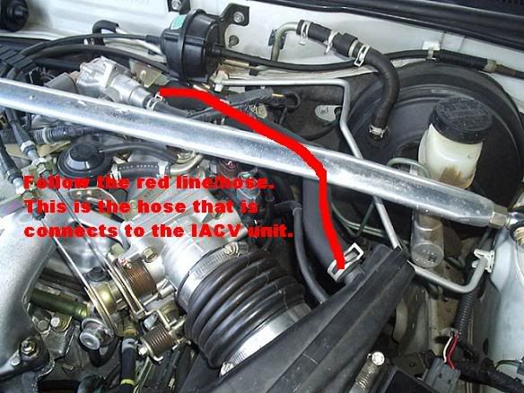
1. Unplug the 4 connectors from the IAC assembly. Undo the hose that connects teh IAC to the intake assembly.
2. The metal bracket holding up the gray-colored connector is blocking one of the IAC mounting bolts. Using a 10mm socket, remove the bolt that holds the metal bracket. The bolt is just below the purple connector - you have to twist your head and crane your neck around to see the bolt.
3. Remove the 3 mounting bolts using the 12mm socket. The lowest bolt may require the Universal joint.
4. Pull out your IAC valve and clean it w/throttle body cleaner, rag, and old toothbrush.
You may even want to separate the plastic valve to clean it more thoroughly. Use a philip's head screwdriver, but make sure it is a snug fight. It's on there tight and if you don't have a good fitting screwdriver, you could ruin the screw head.
Reinstallation is just the reverse of these steps. It may be easier access to the IAC if you remove the whole air intake assembly, but it's not necessary.
How to adjust IACV -
Warm the engine up to operating temp.
Turn off the engine.
Disconnect the TPS.
Start the engine and adjust the idle speed using the stop screw on the throttle body to 650 RPM's.
Turn off the engine.
Reconnect the TPS and restart the engine.
If the IACV is working correctly your idle should be correct. If it's a bit low, try adjusting the screw on the IACV bypass to get your idle speed to ~700 in neutral with no load. (no load means no lights or A/C)
How to test knock sensor - The KS may be checked with an ohmmeter.
1) Raise the hood. View the engine from the driver's fender. Look into
the deep valley between the cylinder banks and below the intake manifold.
Identify the KS as a black item fastened to the block by a single vertical
bolt. A wire harness wrapped in black leads toward you, out of the valley.
That is the KS sub-harness.
2) Follow the KS sub-harness to it's nearest connector. This is connector F121.
It is located near the upper right-hand corner of the valve cover of the forward cylinder bank, as viewed from the front of the car.
3) Disconnect F121. You have to do a "press the latch and wiggle and
pull" to disconnect it. F121 has only two pins; if you see more than two
pins, you have the wrong connector. Use a digital ohmmeter capable of
measuring more than 10 Megohms. You want to measure the pins of F121, not
the sockets of the matching connector. Measure the resistance between a
good ground (such as the battery negative terminal) and pin #2 of connector
F121. On my car this is the highest of the two pins, the one closest to
the front of the car. The factory spec is 500 - 620 Kohms.
Info on Calispec KS install(99) - http://forums.maxima.org/showthread.php?t=233192
How to reset SRS(air bag) light
Open the driver's door. Note the rubber covered button located low on the B pillar, a button which is pressed by the door when the door is closed. This is the Driver's Door Switch (DDS).
Turn the ignition from OFF to ON. Press the DDS at least 5 times within 7 seconds after turning the ignition switch ON. Turn the ignition OFF. Close the driver's door. Start the engine.
If the airbag warning lamp is still on (or still flashing), there is a fault in the Supplemental Restraint System which must be diagnosed and repaired. This is a job for your local friendly Nissan dealer.
60K Service - http://web.archive.org/web/200111091...k_service.html , http://vbxmaxima.8m.com/maintenance.html Many maintenance things can be found in 60K service
How to clean IAC valve
Tools needed:
10 and 12 mm sockets
3 inch socket extension
universal joint (swivel pivot socket thing)
12-inch rachet (a short rachet may not work - need something to apply a lot of torque to loosen the bolts
Philip's screwdriver
rag
throttle body cleaner
1. Unplug the 4 connectors from the IAC assembly. Undo the hose that connects teh IAC to the intake assembly.
2. The metal bracket holding up the gray-colored connector is blocking one of the IAC mounting bolts. Using a 10mm socket, remove the bolt that holds the metal bracket. The bolt is just below the purple connector - you have to twist your head and crane your neck around to see the bolt.
3. Remove the 3 mounting bolts using the 12mm socket. The lowest bolt may require the Universal joint.
4. Pull out your IAC valve and clean it w/throttle body cleaner, rag, and old toothbrush.
You may even want to separate the plastic valve to clean it more thoroughly. Use a philip's head screwdriver, but make sure it is a snug fight. It's on there tight and if you don't have a good fitting screwdriver, you could ruin the screw head.
Reinstallation is just the reverse of these steps. It may be easier access to the IAC if you remove the whole air intake assembly, but it's not necessary.
How to adjust IACV -
Warm the engine up to operating temp.
Turn off the engine.
Disconnect the TPS.
Start the engine and adjust the idle speed using the stop screw on the throttle body to 650 RPM's.
Turn off the engine.
Reconnect the TPS and restart the engine.
If the IACV is working correctly your idle should be correct. If it's a bit low, try adjusting the screw on the IACV bypass to get your idle speed to ~700 in neutral with no load. (no load means no lights or A/C)
How to test knock sensor - The KS may be checked with an ohmmeter.
1) Raise the hood. View the engine from the driver's fender. Look into
the deep valley between the cylinder banks and below the intake manifold.
Identify the KS as a black item fastened to the block by a single vertical
bolt. A wire harness wrapped in black leads toward you, out of the valley.
That is the KS sub-harness.
2) Follow the KS sub-harness to it's nearest connector. This is connector F121.
It is located near the upper right-hand corner of the valve cover of the forward cylinder bank, as viewed from the front of the car.
3) Disconnect F121. You have to do a "press the latch and wiggle and
pull" to disconnect it. F121 has only two pins; if you see more than two
pins, you have the wrong connector. Use a digital ohmmeter capable of
measuring more than 10 Megohms. You want to measure the pins of F121, not
the sockets of the matching connector. Measure the resistance between a
good ground (such as the battery negative terminal) and pin #2 of connector
F121. On my car this is the highest of the two pins, the one closest to
the front of the car. The factory spec is 500 - 620 Kohms.
Info on Calispec KS install(99) - http://forums.maxima.org/showthread.php?t=233192
How to reset SRS(air bag) light
Open the driver's door. Note the rubber covered button located low on the B pillar, a button which is pressed by the door when the door is closed. This is the Driver's Door Switch (DDS).
Turn the ignition from OFF to ON. Press the DDS at least 5 times within 7 seconds after turning the ignition switch ON. Turn the ignition OFF. Close the driver's door. Start the engine.
If the airbag warning lamp is still on (or still flashing), there is a fault in the Supplemental Restraint System which must be diagnosed and repaired. This is a job for your local friendly Nissan dealer.
Last edited by Kevlo911; 02-09-2008 at 07:25 AM.
10-08-2003, 08:25 AM
#29

SC Install Guide For Dummies (credit: ptatohed) - http://www.vqpower.com/v2/infusions/articles/readarticle.php?article_id=73
10-08-2003, 10:30 AM
#30
Member

Join Date: Apr 2003
Posts: 67
Knock Sensor Diagnosis, Test and Installation
Once and for all: a bad knock sensor WILL NOT trip the check engine light, you must extract the codes from the ECU to determine if your sensor is (potentially) bad (code 0304). Some other hints as to a bad KS: poor acceleration below 3000 RPM (I was getting tired of being left behind at stoplights by Honda Civics), reduced gas mileage.
If you don�t already own a Haynes or Chilton manual, get one. In addition to telling you how to extract the codes and locate the KS, there is a wealth of useful information for the do-it yourselfer. I am very cheap, but this an area well worth spending the $20 or so (I bought mine off of EBAY for $10 shipped).
The ECU is located behind the center console on the drivers side. It is accessible by removing the plastic cover panel right next to the gas pedal. The ECU is a metal box with a screw on the side covered by a piece of tape. Peal back the tape to get at the screw. With the ignition in the �On� position, turn the screw all the way clockwise, hold for at least 2 seconds, turn it all the way counterclockwise. Your CEL will now start flashing out any codes stored in the ECU. The codes are two digit numbers. The first number is signaled by long flashes, there will be a two second pause, and the second number will be indicated by a series of short flashes. Long-long-long-pause-short-short-short-short = 0304 (KS fault). There may be more than 1 code in the ECU, they will be flashed out sequentially and the whole sequence will repeat. To clear the codes from the ECU, follow this sequence: clockwise, hold, counterclockwise, hold, clockwise, hold, counterclockwise.
A good KS will measure ~550 k-Ohm resistance between the left pin of the KS and ground. You can check the resistance without removing the KS by following the harness to the connector. The connector has two pins, only one of them hooks up to the KS, so try them both. The act of whacking on the KS with your wrench can (temporarily) start it working again, so checking the KS once you removed it may not give you the bad reading you suspect. Hint: the connector is not the green one closest to the KS that gets in the way of sticking your hand into the engine cavity (1995-1996 models � most likely 1995-1999). The correct connector is a few inches closer to the front of the car. A heat shielded wire leads into the bottom of it and there are two wires coming out the top, one clear and one black.
Low cost knock sensor sources: The dealer will charge you $160 or so for the sensor. I purchased a Nissan OEM sensor off of EBAY for $90 shipped. I have seen them for as little as $80 and routinely for $100-$110. Search for both �Maxima knock� and �Nissan knock� to make sure you get all the possible matches. You can get a Bosch sensors for $115 shipped from http://www.nissanpartstore.com/nissan_knock_sensor.html
Two good article on KS replacement:
http://www.skippynet.com/maxima/knocksensor.htm
http://www.motorvate.ca/mvp.php/507
Modifications to the Skippynet method
The article suggest using a 14� (or longer) �� socket extension to reach the KS retaining bolt. I found that using a 9� extension made it much easier to get the u-joint onto the KS bolt. To save money, I used two 3/8� drive extensions with a 3/8 to � adapter, a �� drive u-joint and a �� 12mm socket (most of which I already had). Skippynet suggest using a 12mm flex socket, but being cheap I used a separate socket and u-joint so that I would have a more useful general purpose tool left over than the 12mm flex socket (better yet, I borrowed the u-joint and saved another $8). A 3/8� u-joint is a slightly bigger animal and in my opinion would make it hard to get the socket onto the bolt. It was not at all difficult to loosen the bolt using this setup. I had also borrowed a 16� extension and found it very difficult to get the socket onto the bolt head (I gave up after about 2 minutes, so it probably could have been done).
Once the bolt was out, I used a magnetic pickup to retrieve it (and eliminate the possibility of dropping it into the engine cavity where as you will find out soon, is not a very friendly place). With the bolt removed, you can pull the knock sensor out of the cavity by the harness and replace it. Next, I put the bolt into the new KS and used a small piece of tape to hold it in place while I stuffed it back into the engine cavity (again to eliminate the chance of dropping it in there).
Now the difficult(ish) part: I don�t see how you can locate the bolt into the hole and get it started without stuffing your hand under the manifold. Others have done it using a claw type pickup to position the bolt so no harm in trying. If you have very large hands, you might try enlisting a girlfriend, your mom or a small child as others have done. I was able to get my hand in there and get the bolt hand tight, then it was just a matter of using the 9� extension/u-joint setup again to do the final tightening. Your hands will get cut up a little doing this, but the term �bloody stump� that gets thrown about is quite an exaggeration.
I was able to replace the KS in both cars in less than 1 hour including test drives using this method. Post installation I got back the power of my VQ and gas mileage increased by 2 MPG.
The real key is using the skippynet socket extension method to crack the bolt loose. Once you have jammed your hand into the engine cavity you will realize how difficult it would have been to get a wrench on the bolt and loosen it.
11-25-2003, 05:50 PM
#31
Where is the thermostat?
The thermostat regulates the flow of coolant within the engine. At low coolant temps, it stays closed. As the engine warms, it opens to allow coolant to flow through the radiator and cool the engine.
It's located on the left side of the engine, here:

If it becomes clogged with deposits it can malfunction. If it sticks closed, coolant will never flow through the radiator and the engine will quickly overheat. If it sticks open, coolant will always flow through the radiator and the car will take a very long time to warm up fully.
The replacement part is $15.99 from AutoZone and includes a new stat mounted in a new housing and gasket.
To change the thermostat:
Drain the coolant
Remove the coolant recovery bottle
Remove the windshield washer fluid filler neck (it pops out)
Remove the hoseclamp and radiator hose from the T-stat
Remove three 10mm nuts holding the T-stat and the old gasket
Installation is the reverse of removal. Cinch
The thermostat regulates the flow of coolant within the engine. At low coolant temps, it stays closed. As the engine warms, it opens to allow coolant to flow through the radiator and cool the engine.
It's located on the left side of the engine, here:
If it becomes clogged with deposits it can malfunction. If it sticks closed, coolant will never flow through the radiator and the engine will quickly overheat. If it sticks open, coolant will always flow through the radiator and the car will take a very long time to warm up fully.
The replacement part is $15.99 from AutoZone and includes a new stat mounted in a new housing and gasket.
To change the thermostat:
Drain the coolant
Remove the coolant recovery bottle
Remove the windshield washer fluid filler neck (it pops out)
Remove the hoseclamp and radiator hose from the T-stat
Remove three 10mm nuts holding the T-stat and the old gasket
Installation is the reverse of removal. Cinch
11-29-2003, 08:03 PM
#32
4th Gen Technical Service Bulletins (TSBs)
*** CTRL + F to search! ***
*** Right click on the link and pick "Save Target As..."
so you can download it to your computer and save
some of my bandwidth ***
*** Also, sometimes the site won't be available if my host is rebooting the
server so try again in a few minutes. If you encounter any problems PM me ***
***
*** CTRL + F to search! ***
*** Right click on the link and pick "Save Target As..."
so you can download it to your computer and save
some of my bandwidth
****** Also, sometimes the site won't be available if my host is rebooting the
server so try again in a few minutes. If you encounter any problems PM me
***Common/Useful TSBs
Wind Noise (Word Document or Web Page)
Interior Squeak And Rattle Repair
"D" Ring Residue Can Cause Slow Seat Belt Retraction
Dash Rattle Noise Caused By Power Brake Check Valve
Timing Chain Rattle Noise
Parking Brake Cable Damage
Front Brake Groan Noise During Stopping
Rear Brake Groan/Humming Noise After Releasing Brake Pedal
Rear Brake Rattle Noise
Front Spring Upper Winding Rattle Noise
EGI Wire Harness Breakage Diagnosis And Repair Procedure
Exhaust Heat Shield Rattle Noise
Thermostats And Heater Performance
Keyless Entry Remote - Battery Replace/Re-Program
Sunroof Water Leaks Due To Rear Drain Tray Guide
Sunroof Rail Assembly Repair
Automatic Transmission (A/T Coolers, Torque Converter)
Automatic Transmission Fluid
Solenoid Valve Replace Procedure - RE4F04A/RE4F04V
A/T Fluid Cooler Cleaning Procedure
A/T Fluid Cooler Cleaning - Rev
Slip/Noise/Hesitate/Stall - RE4F04A
A/T Slips In Reverse After Service
Will Not Shift When Placed In Reverse - RE4F04A
A/T Initial Start Trouble Code Using Consult
A/T Shift Lever Locked In Hot Ambient Temp
A/T Shifter Sticks From Spilled Liquid
OBD-II - "A/T Initial Start" Trouble Code - Rev
Diagnostic Procedure for P0731 and P0733 (A/T Signals) With No Driveability Incidents
Diagnostic Procedure for DTC P0120/P0510/P0731/P0732/P0733 with No Driveability Incidents
Diagnostic Procedure for DTC P0120/P0510/P0731/P0732/P0733 with No Driveability Incidents - Revised
Remanufactured Automatic Transaxle Solenoid Valve Assembly Replacement Procedure
Manual Transmission (Clutch)
Clutch Slip - New Clutch Disc Material
Engine
Timing Chain Rattle Noise
Oil Pan Removal Caution - Dip Stick
Drivability - Check Engine Oil Level & Grade
Oil Filter Application - Not Interchangeable
Brakes
Dash Rattle Noise Caused By Power Brake Check Valve
Front Brake Groan Noise During Stopping
Rear Brake Groan/Humming Noise After Releasing Brake Pedal
Rear Brake Rattle Noise
Squeak/Squeal When Cold
Brake Noise Diagnostic Tips
Parking Brake Cable Damage
Starting and Charging (Battery)
EGI Wire Harness Breakage Diagnosis And Repair Procedure
Cold Weather Starting Tips
Hard/Slow Cranking - Diagn - Ecm
Drivability And/Or Chk Eng Light On -DTC 45 Inj Leak
Crank - No/Hard Start
Intermittent No Start
Intermittent No Start - No DTC's
Reman Starter/Alternator Program
Suspension and Steering
Front Spring Upper Winding Rattle Noise
Strut Replacement Guidelines
Emission Controls and Vacuum Hoses
MIL On - DTC P0443 - Cal Only - Diagnostics
EVAP Purge Control Valve Rev - Active Test Caution
Emissions Label - Calif - Campaign
Emission Insp/Maint Program - I/M 240
All Vacuum Hose Lubricant Applications - Caution To Avoid MIL On Condition
All Vacuum Hose Lubricant Applications - Caution To Avoid MIL On Condition - Revised
Exhaust
Exhaust Heat Shield Rattle Noise
Fuel System
Spark Knock
Spark Knock - A/T W/ Fed Emissions - PCM
Drivability And/Or Chk Eng Light On -DTC 45 Inj Leak
MIL On Or Poor Drivability Due To A/C Evaporator Condensation Leaking On ECM
Fluids/Lubricants
Automatic Transmission Fluid
A/T Fluid - Recommended Types
Recommended Fluids/Lubricants/Chemicals
All Vacuum Hose Lubricant Applications - Caution To Avoid MIL On Condition
A/C Lubricant/Oil - Specs
Sale Of Refrigerant BT Weight Or Volume - Info
Heating and Cooling
Thermostats And Heater Performance
New A/C Connection Rings
EGI Wire Harness Breakage Diagnosis And Repair Procedure
A/C Compressor Leak/Noise Diagnosis
A/C Refrig Capacity Spec - S/M Rev
R134A Charge Amounts/Pag Lubrication Chart
A/C Lubricant/Oil - Specs
Refrigerant Leak Detection Procedure
Refrigerant Leak Detection Procedure - Rev
A/C - R134A Charge Amounts/Pag Lube Chart
A/C Parts - Proper Installation Procedure
MIL On Or Poor Drivability Due To A/C Evaporator Condensation Leaking On ECM
Electrical (Electronic Devices and Sensors)
EGI Wire Harness Breakage Diagnosis And Repair Procedure
Hard/Slow Cranking - Diagn - ECM
MIL On - DTC P0136 (Rear Heated O2 Sensor)
SRS Flashing Light - Diagnostic Fault Tree
OBD-II - "A/T Initial Start" Trouble Code
OBD-II - "A/T Initial Start" Trouble Code - Rev
OBD-II - Powertrain On Board Diagnostics Overview
OBD-II - Eng Control Sys Service Cautions
OBD-II ECM Connector & Bolt - New - Procedure
Drivability And/Or DTC 45 (Injector Leak)
ECCS Testing - Precautions
ECCS System Testing/Diagnosis - Precautions
MIL On - DTC P0340/P1335/P1336/P0335
MIL On - DTC P0443 - Cal Only - Diagnostics
Remote Power Lock/Security Sys Operation Explained
Keyless Entry Remote - Battery Replace/Re-Program
ECM Installation - Seating/Securing The Connector
Rear O2 Sensor Torque Precaution/Specs
ECM Identification & Cross References
Multi-Remote Control Switch Precautions
Theft System - False Alarms - Tips
Diagnostic Procedure For P0731 And P0733 (A/T Signals) With No Drivability Incidents
Remote Control Inoperative
MIL On Or Poor Drivability Due To A/C Evaporator Condensation Leaking On ECM
MIL On - DTC P1335 Due To Harness Contact With Power Steering Pulley
MIL On With DTC P0300 Through P0306 (Multiple Cylinder Misfire)
Diagnostic Procedure For DTC P0120/P0510/P0731/P0732/P0733 With No Drivability Incidents
Diagnostic Procedure For DTC P0120/P0510/P0731/P0732/P0733 With No Drivability Incidents - Revised
Green Or Blue (Fuel Pump & A/C) Relay Caution
Entertainment (Stereo, Radio, Cassettes)
Antenna/Power - Rod Replacement Procedure - Rev2
Poor Radio Reception - Loose Antenna Ground
Diversity & Mast Antenna Isolation Technique
Broken Or Bent Radio Antenna Due To Improper Torque
CD Player Install - Revision To Factory Pre-Wiring
CD Player Installation - Use Vehicle's Harness
Radio Connector Modified - Adapter Harness
Power Antenna Sleeve Available
Audio Sys Data Sheets - Specifications
Reman Bose Speakers Available
Remanufactured Audio Matrix
Interior (Seats, Belts, Interior Trim, And Air Bags)
Interior Squeak And Rattle Repair
"D" Ring Residue Can Cause Slow Seat Belt Retraction
Dash Rattle Noise Caused By Power Brake Check Valve
SRS Flashing Light - Diagnostic Fault Tree
Center Console Lid Latch Replacement
Power Seat Cable
Power Seat Lift Motor Output Gear Stripped
Power Seat Lift Motor Output Gear Stripped - Revised
Air Bag Harness Replacement - Caution
Passenger Side Air Bag Bracket Replacement
Front Seat Belt Extenders Available
Exterior Body, Frame, Paint, And Glass
3-Coat Pearlescent Paint Refinishing - Matching Tips
Sunroof Water Leaks Due To Rear Drain Tray Guide
Sunroof Rail Assembly Repair
Wind Noise Around Front Door
Rear Window Rubber Moulding Replacement Procedure
Rattle/Noise - Spare Tire Cover
Trunk Lid Pops Open
Paint Guard Film - Timing Of Removal
Paint Codes And Clear Coat (NCLC) Identification
New Cross-Linking Clear Coat (NCLC) Polish Procedure
Paint Guard Film - Timing Of Removal - Revised
Paint Stains Under Paint Guard Film
Bumper Refinishing Techniques
Paint Color Code Identification
Paint Codes - 1995 Models
Polyurethane & Polypropylene Bumper Facia Repair
Waterborne Refinish Paints - Approved Suppliers
New Paint Guard Film
Bumper Refinishing Techniques - Models With Plastic Bumper Covers (Fascia)
Tools/Equipment
Theft Protection For Vehicle Components
Spec Tool - Tail Pipe Finisher Installation
VSS Tester Connection Instructions
Essential Tool Release - Various
Tech-Mate Service Equipment & Special Tools Program
Essential Tool - Connector & Terminal Pin Kit
Essential Tool Release
Special Tools - Tech-Mate Spring Promotion
Spec Tools - 1st Qtr Promo Package
Tools - 2nd Quarter Promo Package
Tools - Consult Ue950 Program Card Changes
Tools - Consult Ue951 Program Card Loading Inst
Consult Exchange Program
Spec Tools - 3rd Quarter Promotion
Wheel Balance Machine Adapter Kits
.....................
12-21-2003, 01:12 PM
#33
01-17-2004, 05:47 AM
#34
How To Change Motor Mounts
How To change Motor Mounts:
Holy Lord this isn't an easy job. It only took me 45 minutes to drop the cross member and mounts, but getting everything back together took me nearly 2.5 hours. The problem is that nothing lines up perfectly. My bet is that the rubber in the mounts isn't formed perfectly so whne you reinstall everything, things can be off by 1/8" which is enough to make this job a pita. I had everything in place except one bolt on the front mount where it connects to cross member (more on that later). Here are the tools it took me to get these SOB front and rear engine mounts in place:
1) floor jack
2) two 17mm short sockets
3) ~2.5' of 1/2 extensions
4) 1/2" rachet
5) 18" 1/2" breaker bar
6) jack stands
7) 10mm socket and 1/4" rachet
8) "Bottle" jack http://shop.store.yahoo.com/rodi/mvpbottlejacks.html
9) torque wrench
10) penetrating oil
11) anti-seize
After f-ing around for 3 hours, this is how I made it work.
Installing new engine mounts:
1) Jack the car up, secure with jackstands, and remove the driver's side wheel
2) spray penetrating oil on the bolts and nuts that connect the mount to the engine
3) Using the breaker bar, 2.5' of extension, and a 17mm socket, feed everything through the driver's side wheel well to the rear engine mount bolt and loosen the bolt. This takes some odd leverage and if you're not a decently strong guy, you might be screwed. Also, the amount of extension greatly reduces you're the torque you can generate. You also have to careful and keep the socket on the bolt because the last thing you want to do is strip the head of the bolt. Once the bolt breaks loose, just loosen it, but don't remove. On the rear mount, there is only a bolt. The nut is welded to the "ear" of mount that's connected to the engine block.
4) Using the 10mm socket, remove the two bolts that attach the splash guard to the cross member. Pull the guards down out of the way best you can. They don't need to be removed.
5) Go to the front mount. Using the breaker with a 17mm socket and a rachet with a 17mm socket, break the bolt and nut loose that attaches the mount to the engine. Again, this takes some serious muscle because the leverage is odd and the bolt is on there with ~95 ft/lbs. Again, just loosen this bolt.
6) Take a piece of 2X4 wood and the bottle jack and place the wood between the bottle jack and transmission casing. Jack the tranny up ~1/4". What you are doing is supporting the engine and tranny.
7) Using the breaker bar and a 17mm socket, remove the two front and rear chassis to cross member bolts. Keep the front bolts seperate from the rear bolts BECAUSE THEY ARE DIFFERENT! Something that caught my attention was that these bolts, both front and rear, were only on with about 30 ft/lbs of torque. My Chilton's and FSM both said these bolts are suppose to be torqued to 95 ft/lbs. I'm a bit perplexed at why they were so loose.
8) Once the cross member to chassis bolts are out, wiggle out the mount to engine bolts and nuts, and drop the cross member. It will weigh about ~25lbs.
9) With 17mm sockets on both the breaker bar and rachet, remove the bolts and nuts that connect the mounts to the cross member. There are four of them (two for each mount). Again, leverage of tough and those suckers are torqued to 95 ft/lbs.
10) Install the new mounts to the cross member. Put some anti-seize on the nuts and torque the rear mount bolts/nuts to 75-95 ft/lbs. The reason you use anti-seize is to help the threads stay lubricated and you also get a more accurate torque reading. On the front mount just insert the FRONT bolt into the mount and put the nut (ant-seize it) on finger tight (ie only one of the two bolts on the front mount is attached to the cross member at this time).
11) Lift the cross member into place and slide the rear mount to engine bolt into place and tighten to ~40 ft/lbs.
12) Install the two rear cross member to chassis bolts so that they are slightly tight (~20 ft/lbs, anti-seize them).
13) Slide the front mount to engine bolt into place and finger tightening the nut (anti-seize it).
14) Install the two front cross member to chassis bolts so that they are slighty tight (~20 ft/lbs, anti-seize them).
15) Now the fun part. If your car was like mine, you'll notice that you will not be able to install that front mount to cross member bolt/nut (step 10) because the holes on the mount and cross member don't line up perfectly. Believe me, I tried every different way under the sun to make this work and what I did was the only option on my car. I removed the bottle jack from the tranny (tranny and engine are fully supported by the mounts now) and situated the bottle jack so that it was able to jack up the driver's side lower "ear" of the mount. I slowly jacked up and the mount and cross member holes lined up on that side. The bolt slide through, but now the other side the still wasn't completely lined up and bolt couldn't fully slide through. So I then took my floor jack and used it on the passenger side lower "ear" on the mount. With just some slight jacking, the holes lined up and the bolt slide through. I lowered the jacks and installed the nut (anti-seize it).
I have heard of guys having to enlarge the mount's holes to compensate for this lining up problem. To me, it wasn't an option. I was going to make it work the right way using wrong way methods :LOL:
16) Now all the bolts/nuts were in place and I began torquing all of them to ~77-95 ft/lbs as called for in the FSM. Seeing that the torque numbers are so high, it appears Nissan thinks that these bolts are very important. I suggest torqueing them right.
17) I reinstalled the 10mm splash guard bolts, put the tire back on, and lowered the car.
18) I started her and took her on a test drive and everything seemed fine. There was a little less vibration and 50% of the drivetrain "slop" was gone. The 7-year old mounts I removed weren't torn, but they were a bit softer than the OEM replacements I installed.
With what I know now, I probably could do this job in about 1.5 hours. Like I said, I tried mutliple ways of getting everything to line up, but no matter what, there was always a hole that wouldn't line up perfectly and let me slide the bolt through. I did all the adjusting and jacking on the front mount because it's easiest to get to manipulate. This method worked for my car, but I have no idea about anyone else's. I'm curious to how Nissan techs get everything to line up.
Good luck.
Credit: Dave B, PoePoe2797, Mishmosh
02-18-2004, 06:14 PM
#35
What is the drop resistor mod and how do I do it?
The drop resistor mod disconnects the dropping resistor in the transmission control circuit. This forces the transmission to run a maximum line pressure. This makes the shifts VERY hard. Even an otherwise stock car will chirp the tires on the 1-2 shift with this mod.
The downside is that part-throttle shifts are very jerky. The solution is to wire a Wide Open Throttle (WOT) switch that disconnects the resistor only at full throttle.
Here's Jime's writeup:
Discussion thread in the Nitrous Forum:
http://forums.maxima.org/showthread.php?t=208756
Here's Jime's writeup:
Originally Posted by Jime
Ok here is where the drop resistor is located. Front side of the drivers side strut tower.

There is a connector with two wires attached to the resistor. The electrical drawing of the drop resistor looks like this. You must cut one of the wires, doesn't matter which one but cut it at least 2 or 3 inches from the connector so you have room to strip and connect to it.

Strip a small section on either end of the wire you just cut and attach a wire to each end by soldering or use a connector. Run the two wires to a switch. Either a WOT micro switch (preferably) as per the picture or a manual switch.

I have a small L bracket I made that attaches it to the intake manifold bolt closest to the throttle body.

Keep adjusting the switch position until the throttle hits it just before or when it hits the WOT position. It is imperative that this switch be a Normally Closed (NC) switch so the circuit is always made until you hit WOT at which point it opens and effectively disconnects the drop resistor from the circuit.
You can do the same thing by running the two wires to the cabin and hooking to manual switch (5 amp rating or higher) but I much prefer the WOT switch because you never have to worry about turning it on or off. You have enough to think about when racing without another stupid switch to turn on and off.
The micro switch I use is rated at 10 amps and I got it from an applicance shop where it is used in a microwave.
Most switches of this type are Normally Open (NO) and this will NOT work.
I realize these are pretty crude instructions but I am basically a grease monkey these days not a computer nerd.
There is a connector with two wires attached to the resistor. The electrical drawing of the drop resistor looks like this. You must cut one of the wires, doesn't matter which one but cut it at least 2 or 3 inches from the connector so you have room to strip and connect to it.
Strip a small section on either end of the wire you just cut and attach a wire to each end by soldering or use a connector. Run the two wires to a switch. Either a WOT micro switch (preferably) as per the picture or a manual switch.
I have a small L bracket I made that attaches it to the intake manifold bolt closest to the throttle body.
Keep adjusting the switch position until the throttle hits it just before or when it hits the WOT position. It is imperative that this switch be a Normally Closed (NC) switch so the circuit is always made until you hit WOT at which point it opens and effectively disconnects the drop resistor from the circuit.
You can do the same thing by running the two wires to the cabin and hooking to manual switch (5 amp rating or higher) but I much prefer the WOT switch because you never have to worry about turning it on or off. You have enough to think about when racing without another stupid switch to turn on and off.
The micro switch I use is rated at 10 amps and I got it from an applicance shop where it is used in a microwave.
Most switches of this type are Normally Open (NO) and this will NOT work.
I realize these are pretty crude instructions but I am basically a grease monkey these days not a computer nerd.
Last edited by Kevlo911; 02-09-2008 at 07:26 AM.
07-24-2004, 08:25 PM
#36
Senior Member

Join Date: Apr 2002
Location: Waterloo, Canada
Posts: 325
How do I top up my a/c ?
How do I top up my a/c ?
First off, a warning - if you need to add R-134a to your car it's probably because of a leak. Leaks can leak oil as well as R-134a, so by continually topping up you could be signalling an early end for your compressor as it will run out of lubrication. Topping up the a/c may or may not work for you, and not being a bit careful can make it worse. The best fix is to find the leak, fix it, evacuate and recharge the system. However since most people can't refuse a 10 buck refill kit, the instructions below assume that.
End of warning.....
Our maximas contain an ideal charge of 1.41 lbs (plus or minus 0.11 lbs) of R-134a - often referred to as "freon", but freon is actually the older refigerant R-12 that was phased out in the early nineties due to its ozone-depleting characteristics. 1.41 lbs is just under two 12oz cans. So never add more than two cans to the system.
Assuming everything else in the system is OK, the goal is to refill to around 1.4 lbs of R-134a in the system. How can that be done? It can't accurately be done by pressure, and especially not by low side pressure. Those top-up kits that come with just a low side gauge give you no idea about how much R-134a is in the system and are not accurate, so if you think you need just a top-up don't bother buying one* (explanation at the bottom for those interested).
Manifold gauges on the other hand that show low and high side pressure can get you into the right area because the high side pressure is a better indicator of how much refrigerant you have. In general, it should be somewhere around 2.25 - 2.75 the ambient temperature depending on humidity, engine temperature and other environmental influences. These gauges are required if you'll ever properly service your a/c system yourself because you can attach a vacuum pump to them.
The final, and often overlooked thing to check is the vent temperature. In my opinion this is actually the most important. Even if you don't have any gauges, the vent temperature is an obvious indicator of performance - a cool cabin is what we're looking for after all. If the refrigerant level is too low or too high, the system performance is adversely affected and the temperature goes up, so do the following:
1. Set the engine to 1500 RPM, blower on full cold, windows down.
2. Insert thermometer in center vent. Check temperature.
3. Attach can to the charging hose. Don't connect the fitting to the low side port yet.
4. Open the can tap for a couple of seconds to purge all of the air out of the charging hose - you don't want to force air into your system.
5. Close can tap and connect hose to low side port.
6. Holding the can UPRIGHT, open the tap for five seconds or so, then close again.
7. Wait for at least a minute and check vent temperature.
8. Repeat 6 and 7 until the air is coming out cold (on a 95 degree day the best I could get from mine was about 50). If you notice the temperature starting to go up again, wait another minute and re-check. If it's still high, you may have overcharged.
A word on refrigerant types - don't be tempted by cans with "oil", "leak stop" or "performance additive". Leak stop may prevent an a/c shop from fixing your system down the road because it ruins their expensive machines - expect paying extra to clean up your system before they can even make a start if that's the case. Oil is not recommended because it's the wrong type and you've got no idea how much you've lost. Having a system with too much oil in it harms performance, but this is your call - if you're really worried about oil level you should have it fixed properly.
* Low side only gauges
The maxima compressor contains a variable displacement unit that does not cycle on or off during normal operation. It maintains a constant low side pressure as best it can no matter how much refrigerant is in the system. This is why you can go from an undercharge to an overcharge condition without seeing any noticeable change in the low side. They're also not very accurate, so may do you more harm than good. They may, however, show a serious undercharge. Also, a pressure much above 45-50 points to a serious overcharge, air in the system, or a weak compressor.
07-25-2004, 07:59 PM
#37
How to open your stuck trunk.
How to open your stuck trunk.
If your trunk doesn't pop when you press the button on the door but you do hear a noise this should work. Somehow you moved the "valet" switch in the trunk, this disables the door pop button. If you have a shaved trunk or your key doesn't work for some reason (like me) then here you go. I took some pictures and threw a little something together...
Here's what inside your trunk (valet switch) should NOT look like...

---------------------------------------
---------------------------------------
Here's what yours looks SHOULD look like:

Here's how to open the trunk from the inside, reach in there and use a stick or something, you have to move the lever to the right. That should release the trunk. NOTE: I'm missing a little spring thats supposed to be there but you must not need it? (edit: You do need the spring, my trunk opens if I hit a huge bump.)

GOOD LUCK
If your trunk doesn't pop when you press the button on the door but you do hear a noise this should work. Somehow you moved the "valet" switch in the trunk, this disables the door pop button. If you have a shaved trunk or your key doesn't work for some reason (like me) then here you go. I took some pictures and threw a little something together...
Here's what inside your trunk (valet switch) should NOT look like...
---------------------------------------
---------------------------------------
Here's what yours looks SHOULD look like:
Here's how to open the trunk from the inside, reach in there and use a stick or something, you have to move the lever to the right. That should release the trunk. NOTE: I'm missing a little spring thats supposed to be there but you must not need it? (edit: You do need the spring, my trunk opens if I hit a huge bump.)
GOOD LUCK
08-18-2004, 09:03 PM
#38
How to remove your ECU/PCM
Necessary tools:
*Phillips offset screwdriver
*Pliers
*10mm ratchet (any size drive)
1. Disconnect the negative terminal of your car battery.
2. Remove the plastic covers that protect the ECU; the driver-side cover is to the right of the accelerator. These are secured by two plastic screws and should pop right off.
3. Using a 10mm ratchet, remove the bolt on the passenger side that is securing all the cabling to the ECU
4. Once the bolt is removed, you can detach the cables from the ECU
5. There are four, round, Phillips-head screws that are securing the ECU to the mounting bracket. They can be found in each corner. Due to the close quarters, a standard screwdriver will not work here. Using an offset screwdriver (99 cents at Sears) and a pair of pliers, remove each screw (this step will consume the better part of an hour).
6. Slide the ECU out by pushing from the driver side to the passenger side.
~THT
01-01-2005, 09:57 AM
#39
Steering rack upgrade.
I've seen several threads about swapping steering racks to improve steering feel. However there is misinformation floating around stating that 99 SE Maximas are the only Maximas with the upgraded steering rack. The change was made starting in the 97 Model Year for the SE models only. Therefore 97, 98, 99 SE Maximas use the same steering rack.
Part #s.
95-96 SE + 95-99 GXE/GLE MAXIMAS 49001-40U05
97-99 SE: 49001-0L701
Confirm these steering gear part #s with your own local dealer.
For the other owners if you want to do this upgrade the labor is very expensive so plan to do it yourself to reduce costs. The price of a new rack is over $1,000 so figure out if its something you really want to do.
Steering rack swap
To add to veequeue post about rack swaping i30krab also used a 96 infiniti rack w/ ecs which has adjustable steering
**this rack is very rare and hard t find**
thread here:
http://forums.maxima.org/showthread.php?t=271664
also here are 2 place that sell reman steering racks for a fraction of the price you can find the 97-99 SE racks here as well as the i30 rack w/ ecs sensor:
http://www.meridianautoparts.com/
www.carsteering.com
both place offers 3 yr warranty on the steering racks and i know meridian auto offers lifetime warranty for the rack if you order it through a shop hope this helps
Credit: goodhead
Kevlo911's Steering Rack Replacement How-To
http://www.vqpower.com/v2/infusions/...article_id=111
Credit: Kevlo911
Last edited by Kevlo911; 02-09-2008 at 07:26 AM.
01-21-2005, 08:52 PM
#40

ACC. belt size when removing a/c
you need a 36" serpertine belt if you plan to use stock pulley w/o the a/c compressor, stock size is like 42" or 44" or somethig like that
if you need help or are stuck removing the a/c components, pm me, but its ver simple and straight forward
if you need help or are stuck removing the a/c components, pm me, but its ver simple and straight forward

