Custom Intake Manifold and 87mm Throttle Body


 11-29-2012, 11:32 AM
#83
Senior Member
Thread Starter
iTrader: (6)

Join Date: Aug 2008
Location: Gloucester County NJ
Posts: 1,147
My friend helped me out and did a flow analysis on the current design vs the one I plan on changing it to. Here are the pics
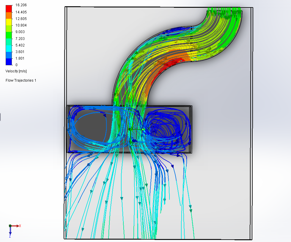
Current Design:
As you can see, there is a major vertex thing going on in the front right corner. Bad design. I should have done this before building it...
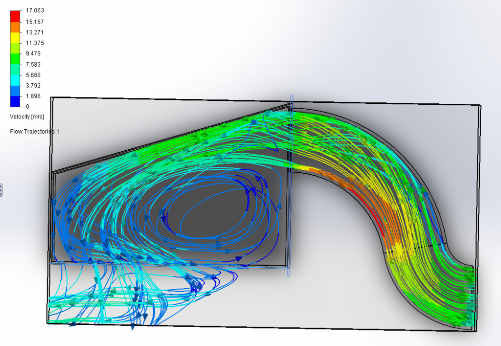
New Design (In Progress):
Much better. Still some vertex things though, but when we modeled it, we made the runners more spaced apart than they actually are, so the vertex regions should not be as severe on the actual manifold. Also, the inlet will now taper out to a 4.5" opening by the time it enters the manifold. I will keep you all updated.
11-29-2012, 12:47 PM
#84
blah of course you are running a maf what was I thinking.
Ever read this?
http://horsepowercalculators.net/int...anifold-design


There is a ton of stuff online about intake manifold design. Best of luck, I would love to see a custom IM tapered log style, 100mm tb, with super short runners.
Or make an intake like the fontana nissan have you seen that one? Highest NA 3.5L I know of.
Ever read this?
http://horsepowercalculators.net/int...anifold-design
There is a ton of stuff online about intake manifold design. Best of luck, I would love to see a custom IM tapered log style, 100mm tb, with super short runners.
Or make an intake like the fontana nissan have you seen that one? Highest NA 3.5L I know of.
Last edited by FastnFuriousMax; 11-29-2012 at 12:51 PM.
 11-29-2012, 05:56 PM
#86
Senior Member
Thread Starter
iTrader: (6)
Join Date: Aug 2008
Location: Gloucester County NJ
Posts: 1,147
I want to make my own complete manifold out of stainless steel. Does anyone have a Solidworks or any other CAD drawing of the lower intake manifold flange? I know Aaron from NWP has to 
Wanna hook me up?
Wanna hook me up?
11-30-2012, 01:26 PM
#89
Senior Member

Join Date: Jul 2009
Posts: 424
 12-02-2012, 01:23 PM
#91
 12-03-2012, 05:02 AM
#92
Hmmm on their website it says 400bhp, and that is just an engine dyno. I would assume 350 at the wheels or slightly more. Maybe 360? SG put more down on their ITBs iirc like 375? Is there another car you were referring to? That is the only one I could find on their site.

Fontana Nissan Z puts down roughly 420-430 hp at the wheels so a brake HP of high 400s I would think. Granted it is a 3.7 vs. a 3.5. That is roughly double what a stock vq puts down with only .3l more displacement.
Either way the intake & cams are a HUGE restriction on the VQ engine.
Fontana Nissan Z puts down roughly 420-430 hp at the wheels so a brake HP of high 400s I would think. Granted it is a 3.7 vs. a 3.5. That is roughly double what a stock vq puts down with only .3l more displacement.
Either way the intake & cams are a HUGE restriction on the VQ engine.
Last edited by FastnFuriousMax; 12-03-2012 at 05:05 AM.
12-04-2012, 12:03 AM
#93

really interested in this.. especially since i'm boosted.
one small thing i noticed before working on my mom's 2002 q45, the q's maf is noticably bigger along with all the intake piping. is it possible for us to use an 02 q45 tb + maf? i pulled a spare maf and the plugs are the same but i didn't feel like looking to see if the throttle body has similar plugs.
just a thought to look into if it hasn't yet. I know the throttle by cable guys use the older q tb's, maybe we wire guys can use this?
 12-04-2012, 06:35 AM
#95
really interested in this.. especially since i'm boosted.
one small thing i noticed before working on my mom's 2002 q45, the q's maf is noticably bigger along with all the intake piping. is it possible for us to use an 02 q45 tb + maf? i pulled a spare maf and the plugs are the same but i didn't feel like looking to see if the throttle body has similar plugs.
just a thought to look into if it hasn't yet. I know the throttle by cable guys use the older q tb's, maybe we wire guys can use this?
one small thing i noticed before working on my mom's 2002 q45, the q's maf is noticably bigger along with all the intake piping. is it possible for us to use an 02 q45 tb + maf? i pulled a spare maf and the plugs are the same but i didn't feel like looking to see if the throttle body has similar plugs.
just a thought to look into if it hasn't yet. I know the throttle by cable guys use the older q tb's, maybe we wire guys can use this?
 12-05-2012, 04:11 AM
#97

really interested in this.. especially since i'm boosted.
one small thing i noticed before working on my mom's 2002 q45, the q's maf is noticably bigger along with all the intake piping. is it possible for us to use an 02 q45 tb + maf? i pulled a spare maf and the plugs are the same but i didn't feel like looking to see if the throttle body has similar plugs.
just a thought to look into if it hasn't yet. I know the throttle by cable guys use the older q tb's, maybe we wire guys can use this?
one small thing i noticed before working on my mom's 2002 q45, the q's maf is noticably bigger along with all the intake piping. is it possible for us to use an 02 q45 tb + maf? i pulled a spare maf and the plugs are the same but i didn't feel like looking to see if the throttle body has similar plugs.
just a thought to look into if it hasn't yet. I know the throttle by cable guys use the older q tb's, maybe we wire guys can use this?
12-05-2012, 02:46 PM
#98

why not post a few sketches on here before actually building the manifold? lots of knowledge on here from a few people.
I built a log style tapered plenum with velocity stacks on a honda F4i as part of a project a while back, can still remember essentially what the facts are about manifold design (did a lot of research and CFD analysis). FYI flat surfaces and square corners suck, avoid those at all costs
I built a log style tapered plenum with velocity stacks on a honda F4i as part of a project a while back, can still remember essentially what the facts are about manifold design (did a lot of research and CFD analysis). FYI flat surfaces and square corners suck, avoid those at all costs
12-06-2012, 04:16 PM
#99
This is what the engine needs. This style is proven to show great gains on other engines. I know a shop that would do it for 1k but i am out of the maxima game. I would love to see one made and a dyno. Should work amazing with a free flowing exhaust and aggressive cams c8, c9, etc.
12-06-2012, 05:21 PM
#100
Senior Member
Join Date: Jul 2009
Posts: 424
This is what the engine needs. This style is proven to show great gains on other engines. I know a shop that would do it for 1k but i am out of the maxima game. I would love to see one made and a dyno. Should work amazing with a free flowing exhaust and aggressive cams c8, c9, etc.
12-07-2012, 05:32 AM
#101

I believed stock motor can make over 300 whp w/o aggressive cam, high cr piston, and pnp head. Just get very serious theory build w/ complete intake and exhaust, then tuned before 7200 rpm for stock con-rod bolt. I wish my se-r have one w/ 5 speed auto. But never happen. That's it!
You would have to take out the lim and create 2 peice manifold with short runners. You should actually reach out to fontana performance to see how the designed theres.
12-07-2012, 10:27 AM
#102
This is what the engine needs. This style is proven to show great gains on other engines. I know a shop that would do it for 1k but i am out of the maxima game. I would love to see one made and a dyno. Should work amazing with a free flowing exhaust and aggressive cams c8, c9, etc.
you could build a custom upper to bolt to the stock lower that would be pretty good, but replacing the lower would be even better. If you replaced the lower you would need to make sure you have the right tech available to make sure you get/build the right length velocity stacks. length of the stack, neck diameter of the stack, and distance from inside edge of the plenum to the top of the stack are all worth spending extra time getting right
12-07-2012, 12:45 PM
#103
Senior Member
Thread Starter
iTrader: (6)
Join Date: Aug 2008
Location: Gloucester County NJ
Posts: 1,147
you can do it on your own for a hell of a lot less than $1k. selecting the correct velocity stacks is the most important part, and they are the most costly too IME
you could build a custom upper to bolt to the stock lower that would be pretty good, but replacing the lower would be even better. If you replaced the lower you would need to make sure you have the right tech available to make sure you get/build the right length velocity stacks. length of the stack, neck diameter of the stack, and distance from inside edge of the plenum to the top of the stack are all worth spending extra time getting right
you could build a custom upper to bolt to the stock lower that would be pretty good, but replacing the lower would be even better. If you replaced the lower you would need to make sure you have the right tech available to make sure you get/build the right length velocity stacks. length of the stack, neck diameter of the stack, and distance from inside edge of the plenum to the top of the stack are all worth spending extra time getting right
I was debating on making my own complete upper with the flange CAD drawing a fellow order sent me, but I feel like I don't know enough about the specifics of manifold design to make it worth my time.
I was thinking about maybe having the flange with 1" velocity stacks sticking straight up, going in to a piece of like 10" diameter pipe cut in half long-ways.
But for now, I'm sticking with my hybrid stock/custom manifold.
What I am about to tackle next is whether I should angle the sizes in towards the rear inlet to make it more of a trapezoidal shape to try and eliminate some of those low pressure vortexes. I don't know how important the extra plenum volume is compared to linear flow...
12-07-2012, 01:10 PM
#104
That is why I opted to use the stock runners from the stock UIM.
I was debating on making my own complete upper with the flange CAD drawing a fellow order sent me, but I feel like I don't know enough about the specifics of manifold design to make it worth my time.
I was thinking about maybe having the flange with 1" velocity stacks sticking straight up, going in to a piece of like 10" diameter pipe cut in half long-ways.
But for now, I'm sticking with my hybrid stock/custom manifold.
What I am about to tackle next is whether I should angle the sizes in towards the rear inlet to make it more of a trapezoidal shape to try and eliminate some of those low pressure vortexes. I don't know how important the extra plenum volume is compared to linear flow...
there is a plenum volume depending on engine size, past which there are basically no gains in HP. I doubt that you are there yet, but from the looks of the modeling you would be better off spending time on getting the flow aligned and eliminating the swirls where you can. If you have a chance to run the modeling again, take a look at moving the "end" of the plenum where it meets up to the stock portion down an inch or more past the end of the runners, so that the runners protrude a bit into the plenum. really need to model at least part of the runners in order to get an idea of what the flow will do, I cant tell if you did that or not in the CFD pics you posted
12-07-2012, 01:40 PM
#105
I have the 75mm TB from the 09 Maxima and boosted as well. The throttle is sensitive when in boost I cant imagine an even BIGGER TB. I think the Q45 TB is about 80mm or 85mm I cant remember exactly. But I think that you will be fine with what TB you have if you are boosted. Are you using a MAF while you are boosted? I think you'll see better results using a MAP sensor instead of a MAF.
I mainly posted the possible q45 maf for n/a guys. I'd love to run an even bigger tb lol. I plan to make more efficient power rather then just raising the boost more.
12-08-2012, 08:33 AM
#106
Senior Member
Thread Starter
iTrader: (6)
Join Date: Aug 2008
Location: Gloucester County NJ
Posts: 1,147
1" stacks would likely be way too short, probably more like 3-5". The stacks I used on the F4i were targeted for peak between 8 and 9k RPM, and I think those were something like 4.5". Its been a couple years so Im not sure
there is a plenum volume depending on engine size, past which there are basically no gains in HP. I doubt that you are there yet, but from the looks of the modeling you would be better off spending time on getting the flow aligned and eliminating the swirls where you can. If you have a chance to run the modeling again, take a look at moving the "end" of the plenum where it meets up to the stock portion down an inch or more past the end of the runners, so that the runners protrude a bit into the plenum. really need to model at least part of the runners in order to get an idea of what the flow will do, I cant tell if you did that or not in the CFD pics you posted
there is a plenum volume depending on engine size, past which there are basically no gains in HP. I doubt that you are there yet, but from the looks of the modeling you would be better off spending time on getting the flow aligned and eliminating the swirls where you can. If you have a chance to run the modeling again, take a look at moving the "end" of the plenum where it meets up to the stock portion down an inch or more past the end of the runners, so that the runners protrude a bit into the plenum. really need to model at least part of the runners in order to get an idea of what the flow will do, I cant tell if you did that or not in the CFD pics you posted
I had a friend help me do the CFD (I don't really know how to use Solidworks). I want to model it again with the sides tapering in to make it trapezoidal and see if it eliminated some vortex areas.
I'm not sure what you mean by moving the end of the plenum, and for the runners, we modeled them as simple holes lol
Is anyone willing to do some CFD's and tell me if my trapezoidal idea helps? I can email you all the Solidworks files...
12-09-2012, 06:17 PM
#107
This should be the right way to do it to keep the air pressure all the way to the last cylinder.
http://www.flickr.com/photos/2073324...n/photostream/
http://www.flickr.com/photos/2073324...n/photostream/
12-10-2012, 07:12 AM
#109
volume isn't much of an issue. the stock manifold shows no gains by doubling the volume.
You can do it yourself for under 1k. Not if you are paying a shop to custom fab one...
I don't see a stock 02-03 block hitting 300whp without cams. I would love to be wrong but I don't see 70whp from just exhaust, intake and a tune.
You can do it yourself for under 1k. Not if you are paying a shop to custom fab one...
I don't see a stock 02-03 block hitting 300whp without cams. I would love to be wrong but I don't see 70whp from just exhaust, intake and a tune.
12-10-2012, 08:11 AM
#110
This should be the right way to do it to keep the air pressure all the way to the last cylinder.
http://www.flickr.com/photos/2073324...n/photostream/
http://www.flickr.com/photos/2073324...n/photostream/
edit: found what the inside looks like
https://www.fontananissanracing.com/...ld_Part_3.html


Last edited by Gemner; 12-10-2012 at 08:26 AM.
12-10-2012, 08:25 AM
#111
"Over the course of this project we have run this engine on a variety of commercially available intake manifolds. Non of those manifolds performed properly with our engine combination. We hand fabricated a manifold that has runner lengths that are designed to give us peak torque in the range this engine requires.
The nearly straight shot design provides optimum flow"


90mm tb used. car puts down 430whp or so they say.
12-10-2012, 08:34 AM
#112
I was actually looking for what it looked like inside. The key is to incorporate the lower so that the runners flow a lot better. Obviously the fontana motor is set very low and maye at an angle to allow for a larger mani.
Last edited by nishfish871; 12-10-2012 at 08:39 AM.
12-10-2012, 08:36 AM
#113
yep. its 420-430 WHP on a 3.8L cosworth stroker, built to Rolex gran am specs and running on motec m800. It looks like a pretty good manifold as far as I can see, but not exactly an apples to apples comparison with what 99.999% of our engines are built to. That said, if you built a manifold modeled on that one I suspect you would be pretty happy with it.
12-10-2012, 08:39 AM
#114
im confused, what part of the manifold is missing?
12-10-2012, 09:07 AM
#115
I can only assume he wants to see from the outside what the lower intake manifold looks like? That is the only picture I can see that is missing.
With the fontana IM there is no more lower/upper. If anything the plate with the stacks is the lower and the upper is just the tapered cover above it.
With the fontana IM there is no more lower/upper. If anything the plate with the stacks is the lower and the upper is just the tapered cover above it.
12-10-2012, 11:37 AM
#116
actually from what it looks like to me, I disagree. It looks to me like they built the upper to bolt to either a stock or lightly modified LIM. The bolt pattern that you can see around the velocity stacks is the same as the stock Z LIM bolt pattern and the picture that nishfish linked to showing the side looks like a cast, stock LIM to me
12-10-2012, 11:56 AM
#117
actually from what it looks like to me, I disagree. It looks to me like they built the upper to bolt to either a stock or lightly modified LIM. The bolt pattern that you can see around the velocity stacks is the same as the stock Z LIM bolt pattern and the picture that nishfish linked to showing the side looks like a cast, stock LIM to me
If they reuse the LIM they probably just port the crap out of it. There is a decent amount of material you can remove iirc.
12-10-2012, 12:42 PM
#118
http://www.flickr.com/photos/20733247@N06/5787808581/in/photostream
thats the link that nishfish posted. can definitely tell its a cast LIM. the bolt holes you can see in the picture I posted above, you can see two larger holes on the end and two smaller holes basically right on the other side of the runner from the larger holes. Presumably there are more bolt holes that you cant see because the velocity stack bells are covering them. looks like the same pattern as stock to me. It makes sense really, there arent really improvements to be made, a runner is a runner and you can just take the length that the stock LIM takes up and subtract it from the ideal length to get your required velocity stack length, plus the ports are already nicely matched and you dont need to measure, design, fabricate a lower

Last edited by Gemner; 12-10-2012 at 12:46 PM.
12-10-2012, 12:59 PM
#119
http://www.flickr.com/photos/20733247@N06/5787808581/in/photostream
thats the link that nishfish posted. can definitely tell its a cast LIM. the bolt holes you can see in the picture I posted above, you can see two larger holes on the end and two smaller holes basically right on the other side of the runner from the larger holes. Presumably there are more bolt holes that you cant see because the velocity stack bells are covering them. looks like the same pattern as stock to me. It makes sense really, there arent really improvements to be made, a runner is a runner and you can just take the length that the stock LIM takes up and subtract it from the ideal length to get your required velocity stack length, plus the ports are already nicely matched and you dont need to measure, design, fabricate a lower
thats the link that nishfish posted. can definitely tell its a cast LIM. the bolt holes you can see in the picture I posted above, you can see two larger holes on the end and two smaller holes basically right on the other side of the runner from the larger holes. Presumably there are more bolt holes that you cant see because the velocity stack bells are covering them. looks like the same pattern as stock to me. It makes sense really, there arent really improvements to be made, a runner is a runner and you can just take the length that the stock LIM takes up and subtract it from the ideal length to get your required velocity stack length, plus the ports are already nicely matched and you dont need to measure, design, fabricate a lower
12-11-2012, 08:12 AM
#120
Senior Member
Thread Starter
iTrader: (6)
Join Date: Aug 2008
Location: Gloucester County NJ
Posts: 1,147
volume isn't much of an issue. the stock manifold shows no gains by doubling the volume.
You can do it yourself for under 1k. Not if you are paying a shop to custom fab one...
I don't see a stock 02-03 block hitting 300whp without cams. I would love to be wrong but I don't see 70whp from just exhaust, intake and a tune.
You can do it yourself for under 1k. Not if you are paying a shop to custom fab one...
I don't see a stock 02-03 block hitting 300whp without cams. I would love to be wrong but I don't see 70whp from just exhaust, intake and a tune.
As far as copying the manifold posted above, it seems like too much work for my case considering I have an internally stock motor. I bet the law of diminishing returns will come in to play there. Might make 275hp with my new manifold and 285hp with that killer manifold...just not worth the work to me. Maybe for someone with a 7th gen motor or a cammed regular DE but not for my old *** VQ.
I will still look into it, but from what I gather so far, it seems like it will be an expensive project for minimal return. I can't even find the velocity stacks for under $40 each.
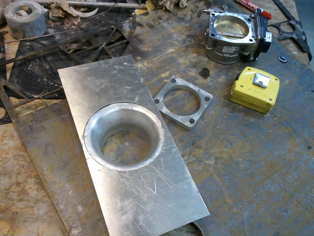
I do have some new pictures though. I made the new back piece with the tapered inlet and cut the flange for the 7th gen throttle body (shoutout to SAL of course):