HOW TO: Add aux to stock bose...
 06-07-2010, 11:46 PM
#241
Newbie - Just Registered

Join Date: May 2010
Posts: 9
Well, after several hours of messing with this, I thought I had it completed. I made all the connections and no wires seemed to be touching on the board. It wasn't the neatest soldering job ever, but I thought it would suffice. Then I soldered the other ends to the jack where I thought was right, based on what made sense to me while looking at the diagram on back. I only used the GRND, L+, L-, R+, and R- because I was just trying to do the mod with the CD changer. I created my silent track CD and plugged my head unit back into the car. At first, everything turned on and I selected the CD Changer and it began playing the silent track......no audio from the ipod  . Not thinking clearly, I just turned the power off and unhooked the head unit again to examine and see if I could figure it out. I thought I must have not soldered the connections right and i pulled them off by holding the soldering iron on each one for a second until it melted back down. I went back out and plugged the unit back in (back to stock) and nothing powered on.....uh oh. The first thing I thought is that I blew a fuse. I found the fuse labeled "audio" and pulled it.....blown. I didn't see a fuse labeled "radio" or anything else that seemed like it had to do with the head unit, but I was immediately fearing that the audio fuse had blown sometime and when I plugged everything in the first time I wasn't getting sound because the "audio" fuse was already blown and that there may be another one that is blown making it not power on. I really wish I had tried the radio also when I first plugged it in to see if I was getting sound at all! So it's late, I don't have a spare 15 amp fuse, and my head unit and navigation don't power on as of right now. My entire dash is torn apart and I made no progress......FML.
. Not thinking clearly, I just turned the power off and unhooked the head unit again to examine and see if I could figure it out. I thought I must have not soldered the connections right and i pulled them off by holding the soldering iron on each one for a second until it melted back down. I went back out and plugged the unit back in (back to stock) and nothing powered on.....uh oh. The first thing I thought is that I blew a fuse. I found the fuse labeled "audio" and pulled it.....blown. I didn't see a fuse labeled "radio" or anything else that seemed like it had to do with the head unit, but I was immediately fearing that the audio fuse had blown sometime and when I plugged everything in the first time I wasn't getting sound because the "audio" fuse was already blown and that there may be another one that is blown making it not power on. I really wish I had tried the radio also when I first plugged it in to see if I was getting sound at all! So it's late, I don't have a spare 15 amp fuse, and my head unit and navigation don't power on as of right now. My entire dash is torn apart and I made no progress......FML.
Last edited by xTyD23x; 06-07-2010 at 11:49 PM.
 08-15-2010, 11:57 AM
#242

I started this project not long ago and I get audio from my ipod(when in FM strangely, find a quite station and i can run the ipod all day) but I cant get the HU to go into AUX mode. I have a switch connected to the "AUX-ON" and "Ground" on the HU but it doesnt do anything, so i just tried touching the wires together m manually and still nothing.
I probably just missed something somewhere and am too stupid to find it. Ive been reading this thread and others all day trying to figure it out.
Edit: Sorry, I forgot to add that i have a '95
Edit 2: Well i found out that I can just use a "silent track" in my cd player and play the ipod. it works great, but I would still like to know why i cant get it into "AUX mode"
Last edited by SrgScott; 08-15-2010 at 12:34 PM.
10-26-2010, 07:20 AM
#243
Newbie - Just Registered

Join Date: Sep 2010
Posts: 1
to all i have found matt cervi's email address upon searching the genious behind it all, and he so graciously sent me the pdf and txt file of the components (which is no longer available on the internet that i know of) i will ask his permission to repost it to a server so we can all have access to it, he wished me best of luck to my project. this is for my 3rd maxima 95 maxima gle. just wrecked my 96 nissan maxima gxe, and salvaged some parts and sold the rest. i gave my buddy my first 1990 maxima gle years ago. even though this islike my first post, i have been reading this forum for years just soaking in knowledge, decided to take action and finally post something and will post pictures and videos of my project as well when finished. sorry if bringing this post back from the dead (its a stickie so i get a late pass right?) it would be great to know how everyone else who did this mod how it is working for them currently, i am planning on using it for my computer getting a touch screen to cover the bose unit (like a cabinet door) and wiring it to a computer (probably from mp3car.com) and using the software (the free dyno app) for the 4th gen maximas to connect to the port by the fuses via usb or go with the ot-2 which is a bitmore expensive but no wiring which is cooler just a bit worried about security and would rather connect to other internet sources at the same time. wish there were some linux capabilities, including gps, mp3s, dvds, etc. might need to re-read some linux programming books and make a good maxima-based linux os. converting the free dyno app to linux as well, since linux is free and open source.
holla, x.
holla, x.
Last edited by greeneggy; 10-26-2010 at 07:30 AM.
 01-08-2011, 08:34 PM
#245
Supporting Maxima.org Member


Join Date: Sep 2003
Posts: 110
http://www.youtube.com/watch?v=rKGKB0vUqvg
.
Thanks for the great youtube write up. I did this on my 2003 Max over the weekend and it worked out great. I lifted/bent the cover up enough to solder the three wires to the cassette board without having to remove the whole unit from the brackets. Those side screws are tough to remove. Sound quality is very good. I bought a TomTom navigation adapter for IPOD Touch on Amazon for about $35 then "purchased" the TomTom app that cost $39. I mounted the TomTom holder right above the A/C vents and ran the power wire and sound wire through the A/C vent duct. I installed a power socket behind the dash. One problem left to solve....I am getting the typical engine whining sounds. I am guessing I need to find a better way to ground the hard wired cable thinking I am causing a ground loop issue. I tried the PAC-SNI-1 and it eliminated the whinning but killed the output sound level. I know that running a power line next to a sound line is typically a problem. I may consider wrapping the hardwired 3.5 wire with shielding to block the sound. I was thinking of removing the ground wire from the tape players circuit board and running it to metal frame ground. I welcome any suggestions on the ground loop/whinning sound.
02-04-2011, 02:28 PM
#246
Newbie - Just Registered

Join Date: Sep 2007
Posts: 4
Just completed this job, works fine. I have a 95 GLE.
My HU went to AUX mode when I connected AUX to RXD, not GND!!!
Soldering was by far hardest part ... for me, so I suggest
using CD changer pins first from the back of the HU.
Get a mating Molex, run AUX to RXD thru an on-off switch
and your HU is ready for R+, R- and L+, L- inputs.
I used 6 wires, not 7.
Some static in AUX mode when nothing connected, but not noticable at all
when playing music.
Thanks all.
Last edited by dicknn; 02-04-2011 at 03:15 PM.
04-11-2011, 02:36 PM
#247
Newbie - Just Registered

Join Date: Apr 2011
Posts: 9
Instead of soldering to the circuit board (I suck at soldering), I used small crimp connectors to secure wires to the pins on the CD Changer connector. I used the pin-out diagram referenced in Dan's original email. I've got a 96 and I had to wire my switch between the "CD-Combi (RXD)" and "AUX-ON" pins. I haven't had any trouble with volume from my Treo.
I ran the switch and 1/8" jack through my ashtray so that the modification is invisble when the ashtray is closed. Many thanks to Dan - it's very cool to be able to hook up my Treo through an AUX connection.
I ran the switch and 1/8" jack through my ashtray so that the modification is invisble when the ashtray is closed. Many thanks to Dan - it's very cool to be able to hook up my Treo through an AUX connection.
04-17-2011, 08:27 PM
#248
Newbie - Just Registered

Join Date: Apr 2011
Posts: 1
Howdy - This thread was a great inspiration to me. Although the method stated here does not work on my 01 i30, I was able to find an alternative, similar method and thought I would share.
My car did not come with the optional CD Changer. And although I have the CD/Changer button on my HU, the PCB and changer plug does not have the AUX-ON circuit. Through much testing, I tried to use the method posted on this thread, but could not get anything to work.
But, I did find that there is a way to tap into the actual CD player on the head unit. By creating a ground short to the CD players Reset, you can basically put the CD player in a Pause state. With an aux jack wired into the L and R outputs from the CD player, you can then stream a phone/mp3 player/etc.
I have a thread over on a different forum with a complete write-up and even a demo video, and I thought I would share so that anyone who doesn't have the option to use the CD-changer hack, might have a chance at a different method. Here is the link:
http://forums.nicoclub.com/post6065151.html#p6065151
I am not trying to hijack this thread so I apologize if posting a link to another forum is out of line, but I know resources of this kind for this project is very limited and I wanted to give people another resource that might help them out.
Thanks and good luck!
 06-01-2011, 07:19 AM
#250
Supporting Maxima.org Member

Join Date: Aug 2001
Posts: 1,362
It is hard to make out any details in the video. Does anyone have any close up pics of where you solder? It looks like three wires - is it Left, Right, and common ground?
It looks like you have to 'trick' the tape deck into thinking there is a tape in there. How did you guys do it? Right now my tape deck will spit out any tape I put in it and give the tape error message. I don't care if I ruin the tape deck since I never use it.
Last edited by Anachronism; 06-01-2011 at 07:21 AM.
03-13-2012, 03:47 PM
#251

So it seems this has been done to my Maxima already. I'm not sure if it was done right now, when I switch the AUX on and plug my iPod in, it gives only some of the sound and not all of it. Kinda seems like it's not plugged in all the way. Does anyone else have this same issue? I bought the car with the aux cable already installed.
04-19-2012, 02:14 PM
#252
Newbie - Just Registered

Join Date: Nov 2008
Location: Logan, Utah
Posts: 15
Just finished this mod! It's WAY EASIER than it used to be if you get yourself a harness from MaximaJoe or just simply solder to the CD changer pins.
NO need to open the radio for any reason! I used 6 wires. (2 bottom furthest right) These two when bridged make it go into AUX mode.
Then you use the 2 furthest left top and the 2 furthest left bottom.
(This is as if you are looking at the back of the radio at the CD Changer plug)
Again I just bought a harness from MaximaJoe so I simply plugged it in and then wired the other ends in this fashion:
LCH+ to Positive Left Channel (center pin on RCA connector)
LCH- to Negative Left Channel (outside lead on RCA connector)
RCH+ to Positive Right Channel (center pin on RCA connector)
RCH- to Negative Right Channel (outside lead on RCA connector)
I then went from RCA to 3.5mm and made a nice connector in the center console.
As for the switch, this is the ULTIMATE in perfect matching perfect fitting. I didn't need to glue it at all because it was such a perfect fit. Sits right between the heated leather seat switches and looks identical to them!
http://www.radioshack.com/product/in...ductId=3097457
I will hopefully post pictures soon. This mod really is easy as pie and is a must for anyone with a stock stereo!
Also forgot to add, some people have complained about it not being loud? Those people must be deaf. On an old ipod and my iphone it's loud enough to blow the speakers if I wanted it to. Sound is PERFECTLY clear too. Just as good as any CD I have listened to.
04-24-2012, 05:56 AM
#253
Supporting Maxima.org Member
Join Date: Aug 2001
Posts: 1,362
Just finished this mod! It's WAY EASIER than it used to be if you get yourself a harness from MaximaJoe or just simply solder to the CD changer pins.
NO need to open the radio for any reason! I used 6 wires. (2 bottom furthest right) These two when bridged make it go into AUX mode.
Then you use the 2 furthest left top and the 2 furthest left bottom.
(This is as if you are looking at the back of the radio at the CD Changer plug)
Again I just bought a harness from MaximaJoe so I simply plugged it in and then wired the other ends in this fashion:
LCH+ to Positive Left Channel (center pin on RCA connector)
LCH- to Negative Left Channel (outside lead on RCA connector)
RCH+ to Positive Right Channel (center pin on RCA connector)
RCH- to Negative Right Channel (outside lead on RCA connector)
I then went from RCA to 3.5mm and made a nice connector in the center console.
As for the switch, this is the ULTIMATE in perfect matching perfect fitting. I didn't need to glue it at all because it was such a perfect fit. Sits right between the heated leather seat switches and looks identical to them!
http://www.radioshack.com/product/in...ductId=3097457
I will hopefully post pictures soon. This mod really is easy as pie and is a must for anyone with a stock stereo!
Also forgot to add, some people have complained about it not being loud? Those people must be deaf. On an old ipod and my iphone it's loud enough to blow the speakers if I wanted it to. Sound is PERFECTLY clear too. Just as good as any CD I have listened to.
NO need to open the radio for any reason! I used 6 wires. (2 bottom furthest right) These two when bridged make it go into AUX mode.
Then you use the 2 furthest left top and the 2 furthest left bottom.
(This is as if you are looking at the back of the radio at the CD Changer plug)
Again I just bought a harness from MaximaJoe so I simply plugged it in and then wired the other ends in this fashion:
LCH+ to Positive Left Channel (center pin on RCA connector)
LCH- to Negative Left Channel (outside lead on RCA connector)
RCH+ to Positive Right Channel (center pin on RCA connector)
RCH- to Negative Right Channel (outside lead on RCA connector)
I then went from RCA to 3.5mm and made a nice connector in the center console.
As for the switch, this is the ULTIMATE in perfect matching perfect fitting. I didn't need to glue it at all because it was such a perfect fit. Sits right between the heated leather seat switches and looks identical to them!
http://www.radioshack.com/product/in...ductId=3097457
I will hopefully post pictures soon. This mod really is easy as pie and is a must for anyone with a stock stereo!
Also forgot to add, some people have complained about it not being loud? Those people must be deaf. On an old ipod and my iphone it's loud enough to blow the speakers if I wanted it to. Sound is PERFECTLY clear too. Just as good as any CD I have listened to.
I attempted the internal mod on my Bose with 6cd in dash changer but I could not get the radio to stay in tape mode
 As I mentioned before my cassette deck would spit out any cassette that was put in there, so using any kind of blank or dummy cassette was out. I tried every combination of messing with all the little levers with no success. I even found the terminal that would switch to tape mode when grounded, but it would give the tape error message after a few seconds and cut the audio. I ended up going with an aftermarket radio with an AUX in.
05-07-2012, 08:24 PM
As I mentioned before my cassette deck would spit out any cassette that was put in there, so using any kind of blank or dummy cassette was out. I tried every combination of messing with all the little levers with no success. I even found the terminal that would switch to tape mode when grounded, but it would give the tape error message after a few seconds and cut the audio. I ended up going with an aftermarket radio with an AUX in.
05-07-2012, 08:24 PM
#254
 09-15-2012, 07:53 PM
#257

I started this project not long ago and I get audio from my ipod(when in FM strangely, find a quite station and i can run the ipod all day) but I cant get the HU to go into AUX mode. I have a switch connected to the "AUX-ON" and "Ground" on the HU but it doesnt do anything, so i just tried touching the wires together m manually and still nothing.
I probably just missed something somewhere and am too stupid to find it. Ive been reading this thread and others all day trying to figure it out.
Edit: Sorry, I forgot to add that i have a '95
Edit 2: Well i found out that I can just use a "silent track" in my cd player and play the ipod. it works great, but I would still like to know why i cant get it into "AUX mode"
I probably just missed something somewhere and am too stupid to find it. Ive been reading this thread and others all day trying to figure it out.
Edit: Sorry, I forgot to add that i have a '95
Edit 2: Well i found out that I can just use a "silent track" in my cd player and play the ipod. it works great, but I would still like to know why i cant get it into "AUX mode"


 01-08-2013, 06:19 AM
#261
Member

Join Date: Jun 2011
Posts: 111
I have a 96 maxima that I got with a 99 Bose Stock Stereo. I've tried to install an AUX cable by connecting it to the circuit board and nothing worked. My CD player gives me CD ERR anytime I try to play a CD so that may be apart of it. I gave up and use a tape deck now.
01-08-2013, 09:19 AM
#262
Senior Member

Join Date: Sep 2007
Posts: 1,042
No, this mod works. Weird thing. The radio I got has the 97/98 face but the circuit board of my 99 and the lettering on where to connect the switch and sure enough it worked. Upon looking at my original headunit. I seen corrosion on certain parts of the board. And it did look like it got wet in the past. The stereo reception wasnt all that good also. So I think it had something to do with that...I think the heater core or something went bad. Cause they removed the dashboard. Which is weird cause the car had 100k when I bought her. The light sensor was removed and not mounted. And the cabin temp sensor wasn't installed either and the hose wasn't connected either. So now it works perfectly. So to confirm yes it works for 99 Bose headunit.
01-12-2013, 11:05 PM
#264
I did it last summer on my 95 GLE. The aux on/off switch did not work as the op described. No big deal, a silent CD is enough to get around the problem. In fact, I kinda like this way - no additional switch needed. If I need to listen to the iPhone, simply pop in the silent cd (labeled iPhone) and plug in the iPhone to the new jack. (I don't have fog light, so I simply install the new3.5mm jack on the plate where fog light switch would be). I am very happy with the result, might be doing the same for my landcruiser.
As mentioned in previous post, the ear phone output is to weak, you should get a charger cable with line out built-in.
As mentioned in previous post, the ear phone output is to weak, you should get a charger cable with line out built-in.
01-22-2013, 08:26 AM
#265
Junior Member

Join Date: Nov 2012
Posts: 37
I did it last summer on my 95 GLE. The aux on/off switch did not work as the op described. No big deal, a silent CD is enough to get around the problem. In fact, I kinda like this way - no additional switch needed. If I need to listen to the iPhone, simply pop in the silent cd (labeled iPhone) and plug in the iPhone to the new jack. (I don't have fog light, so I simply install the new3.5mm jack on the plate where fog light switch would be). I am very happy with the result, might be doing the same for my landcruiser.
As mentioned in previous post, the ear phone output is to weak, you should get a charger cable with line out built-in.
As mentioned in previous post, the ear phone output is to weak, you should get a charger cable with line out built-in.
02-07-2013, 04:52 AM
#266
Newbie - Just Registered

Join Date: Jan 2013
Location: Toronto, ON
Posts: 1
Howdy - This thread was a great inspiration to me. Although the method stated here does not work on my 01 i30, I was able to find an alternative, similar method and thought I would share.
My car did not come with the optional CD Changer. And although I have the CD/Changer button on my HU, the PCB and changer plug does not have the AUX-ON circuit. Through much testing, I tried to use the method posted on this thread, but could not get anything to work.
But, I did find that there is a way to tap into the actual CD player on the head unit. By creating a ground short to the CD players Reset, you can basically put the CD player in a Pause state. With an aux jack wired into the L and R outputs from the CD player, you can then stream a phone/mp3 player/etc.
I have a thread over on a different forum with a complete write-up and even a demo video, and I thought I would share so that anyone who doesn't have the option to use the CD-changer hack, might have a chance at a different method. Here is the link:
http://forums.nicoclub.com/post6065151.html#p6065151
I am not trying to hijack this thread so I apologize if posting a link to another forum is out of line, but I know resources of this kind for this project is very limited and I wanted to give people another resource that might help them out.
Thanks and good luck!
My car did not come with the optional CD Changer. And although I have the CD/Changer button on my HU, the PCB and changer plug does not have the AUX-ON circuit. Through much testing, I tried to use the method posted on this thread, but could not get anything to work.
But, I did find that there is a way to tap into the actual CD player on the head unit. By creating a ground short to the CD players Reset, you can basically put the CD player in a Pause state. With an aux jack wired into the L and R outputs from the CD player, you can then stream a phone/mp3 player/etc.
I have a thread over on a different forum with a complete write-up and even a demo video, and I thought I would share so that anyone who doesn't have the option to use the CD-changer hack, might have a chance at a different method. Here is the link:
http://forums.nicoclub.com/post6065151.html#p6065151
I am not trying to hijack this thread so I apologize if posting a link to another forum is out of line, but I know resources of this kind for this project is very limited and I wanted to give people another resource that might help them out.
Thanks and good luck!
 also it cost me $0 to do as i have a lot of junk laying around (the swich is from an old pc) compared to the 150+ I would have spent on an aftermarket HU. Stock HU with 4 kicker ds65's and I'm content. Thanks a lot mate for the write up!
02-07-2013, 09:53 AM
also it cost me $0 to do as i have a lot of junk laying around (the swich is from an old pc) compared to the 150+ I would have spent on an aftermarket HU. Stock HU with 4 kicker ds65's and I'm content. Thanks a lot mate for the write up!
02-07-2013, 09:53 AM
#267
Junior Member
Join Date: Nov 2012
Posts: 37
Hi! I'd like to confirm that your method works great for me too! 99 es (Can) with clarion HU. The only 'problem' is that I have to switch off the car if I want to listen to a cd, but it's nothing also it cost me $0 to do as i have a lot of junk laying around (the swich is from an old pc) compared to the 150+ I would have spent on an aftermarket HU. Stock HU with 4 kicker ds65's and I'm content. Thanks a lot mate for the write up!
also it cost me $0 to do as i have a lot of junk laying around (the swich is from an old pc) compared to the 150+ I would have spent on an aftermarket HU. Stock HU with 4 kicker ds65's and I'm content. Thanks a lot mate for the write up!
02-26-2013, 04:10 PM
#268

It works! Connecting the RXD wire to AUX-ON wire using a SPTD switch puts the BOSE into AUX mode. Instead of soldering onto the stereo's PCB I made a harness with a J202 connector to insert to the CD changer input in back of the HU. I can now play music with my IPOD NANO or smartphone hooked up. The 4 speaker wires (L-, L+, R-, R+) also need to be spliced onto a 1/8" jack.
Thank you Dan for the hints.
Thank you Dan for the hints.
02-28-2013, 04:37 PM
#269
As stated in the previous post I didn't need to solder the PCB within the HU. I just dug up the connector for the CD changer and harnessed 6 wires on it.
If any of you want to try soldering within the HU to get the AUX mode working then here's all the info you'll need
1995_Maxima_SE_Bose_HU_AUX
If any of you want to try soldering within the HU to get the AUX mode working then here's all the info you'll need
1995_Maxima_SE_Bose_HU_AUX
06-08-2013, 09:54 AM
#270
Newbie - Just Registered

Join Date: Jun 2013
Location: SoCal
Posts: 3
I have been wanting to hook my iphone to my Bose forever....
Thanks to everyone that has pioneered this upgrade.
I'm going to start collecting parts to do the mod. Is the J202 connector available online? I googled it but nothing really came up. Somewhere in this thread someone mentioned a D Sub kit from radio shack and taking the connectors from that. I think that would work ok.
Or, is there a factory J202 connector already in the car? I'll never put a cd changer in it so I could use the existing plug if it is already there.
Thanks again for a great site. I been lurking here for a while now. So much information.
Take care,
Dave
06-12-2013, 07:33 PM
#271
Newbie - Just Registered
Join Date: Jun 2013
Location: SoCal
Posts: 3
Just a quick update.
I found out that servo extensions for radio controlled planes, cars, etc have the correct size pins and sockets to plug into the back of the radio for the Aux Mod. They are available at most any hobby shop.
Took me a couple hours to do the complete job and am very happy with the results.
Thanks again,
Dave
08-07-2013, 09:07 PM
#276
The link I provided in post 269 will show you step by step how to solder wires onto the HU PCB. It is not labelled AUX. You'll have to re-read this thread and the link I provided.
08-08-2013, 12:17 AM
#278
 08-09-2013, 02:10 PM
#280

1. The hardest part by far (in my opinion anyways) is getting the radio out for the first time. The guide here -> http://www.installdr.com/InstallDocs...PDF/647021.pdf is for a non-bose radio, but the process is the same. Damned clips, they make it really easy to get stuff in, but very difficult to get out. Take your time and be careful not snap any of the plastic parts.
2. Go inside and clear a workspace - you don't want to lose any screws. Unscrew ALL the screws on one side of the console, and the four holding the radio in on the other side. You should be able to slide it out. If you don't unscrew everything on one side, it's a pain to get out, and you risk snapping something, so don't be lazy!
3. Flip the radio upside down on the table (the side without the label). Unscrew the two small screws near the faceplate that are holding the metal plate down. Look on the side of the radio, you'll see two slots near the top, insert a flathead screwdriver and twist to pop the clips free. Do this for all four. you should be able to take the plate off now.
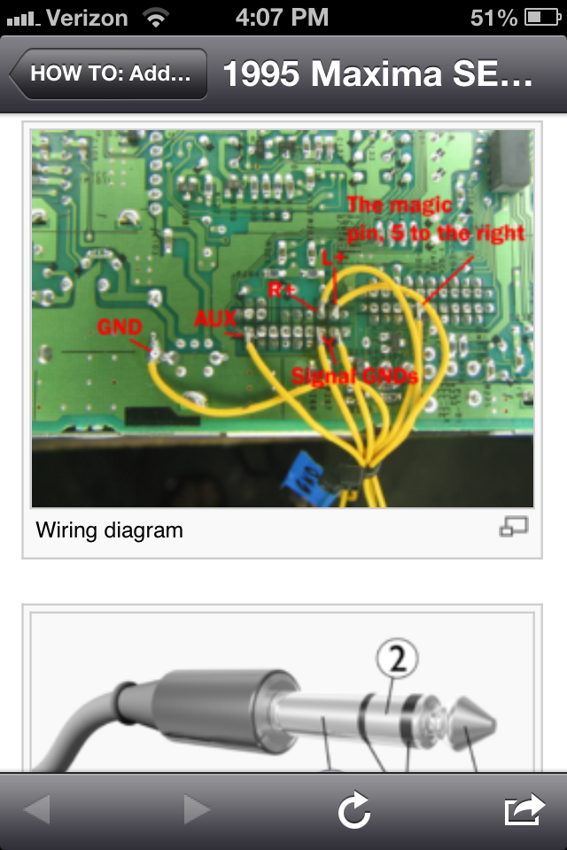
Wiring diagram
1. Sleeve: ground
2. Ring: Right channel
3. Tip: Left channel
(pay no attention to the lower half of the picture)
4. Using the picture to the right, solder whatever hookup wire you'd like to the appropriate pins. It's a good idea to use a short length of heat shrink tubing to prevent possible shorts. Be sure to label all wires, and twist together the common wires: the two signal ground, the AUX and ground, and L+ and R+. You'll need to wire up a SPST (single pole, single throw) on/off switch (not a momentary switch, i.e. it has two positions, and it stays in either position). One side of the switch will be tied to the AUX pin in the picture, the other to the "magic pin" in the picture. You'll also need to wire up either a 1/8" socket, or jack. Look at the diagram for a reference - I used the cable from some crappy airplane headphones.
5. a. If you want to do what I did and add a toggle switch or a female 1/8 jack on the front panel, unscrew the small screws holding on the faceplate on and unsnap it. If you have a low profile switch, you may be able to avoid cutting the board to make it fit. Either way I would suggest taking a dremel and milling out the plastic pins that stick up on the lower left (looking from behind) of the faceplate. You can then drill a hole large enough for your switch, pushbutton or 1/8" jack. If whatever you decide to use sticks out too much in back, don't worry too much. The portion of the board directly where we're putting our switch looks like it was designed to have a button at some point, but I guess they may have left it out at the last minute, who knows.
In any case you can safely cut out a small section of the board with a coping saw or something similar. Before cutting the PCB, trace where you plan to cut and trace what leads you'll be severing to confirm that you won't do any real damage. Be careful when cutting fiberglass because the dust should NOT be inhaled, use a respirator if you have access to one. If like me your jack or switch has a threaded collar, the design of the plastic is great, you can drill a hole just too small for the switch all the way through. I chose to drill exactly where the center pin was (of the three that we milled out with a dremel) however, if you wanted you could probably drill where both the outside ones were and install a jack and toggle. Then drill a slightly larger hole in the above layer of plastic.
Put one of the nuts on the threaded collar and slide the other in between the two layers of plastic. Screw the switch into the bottom nut, and then into the plastic until it is flush with the outside. Tighten the two nuts as best you can. Epoxy can be used to reinforce the switch and keep it from ever unscrewing in the future. I had to dremel the edge of the clear light spreader thingy in order to fit it back in after I installed the switch.
Pin-out diagram for the bose HU
5. b. If you want to do something else; read what I said above for some ideas, and have a go at it, for this step you can really do whatever you'd like. I'd be interested to see what you come up with. Just one note though: when drilling the faceplate, avoid the thin layer that the large clear light spreader lies in, it appears that the plastic is flimsy, and would not look good on the outside.
6. Whichever version of step 5 you decided to do, you'll still need to feed the wires through the holes in the top of the metal plate and solder them to your switch and 1/8" jack or plug. If you installed a jack or switch in the faceplate, feed the wires through the holes in the bottom of the faceplate and solder them in place. Snap the plate back on and remember to put the screws back. Install the faceplate.
7. Before putting everything back together, take the radio out to your car and make sure everything works. If it does, you're done! Reassemble everything and enjoy your music!
If you have any trouble that you can't resolve, feel free to post on http://forum.ryft.org to ask for help.
8. Set up your jack. What I did was route my male 1/8" jack out from the base of the center console at floor level. In the future I'm planning on mounting a dock of sorts for my Zen on the right of the center console in the same fashion as some cell phone holders. I have a car charger for my Zen that I would connect within the center console and then route the cable along the same path as the 1/8" jack to connect to the docking station, giving me charge and playback simply by sliding the zen onto the dock.
Disclaimer: Use common sense, don't solder yourself, stab yourself with a screwdriver or hurt yourself in any other way! Neither ryft.org nor the author of this article can be held accountable for any damage you do to your property or someone else's while attempting this mod.