
Apexi Neo


Apexi Neo
Guys,
I picked up the Apexi Neo, but I'm having a time finding out all the wiring advice I need.
A lot of the old writeups from SafcII have broken links
I was in search of some basic guidance to wiring and baseline tuning.
I've read quite a bit and I'm a hands on person... before I get into the car to mess with things they are hard to understand.
Let me know any information you require.
Last edited by adrenaline_rush_fanatic; Jan 30, 2012 at 09:13 AM.

How do you know you're running rich?


Same principle applies as as far as MAF signal, GND, RPM, TPS, etc goes.
What do you mean locked for you?
try this:
http://forums.maxima.org/5th-generat...on-thread.html
Same principle applies as as far as MAF signal, GND, RPM, TPS, etc goes.
What do you mean locked for you?
try this:
http://forums.maxima.org/5th-generat...on-thread.html
I try and follow that link and always get this Server Error: The website encountered an error while retrieving http://forums.maxima.org/5th-generat...on-thread.html. It may be down for maintenance or configured incorrectly.
What principle exactly? cutting the wire on ecm and soldering the wire from pigtail of apexi wiring harness?
Sorry to ask dumb questions, I just want to explicitly understand what I am doing as I trying to wrap my head around everything before I tackle it.
I'm a hands on learner so I'm headed now to unbolt the ecm plug and start messing with it.
Same principle applies as as far as MAF signal, GND, RPM, TPS, etc goes.
Sorry to ask dumb questions, I just want to explicitly understand what I am doing as I trying to wrap my head around everything before I tackle it.
I'm a hands on learner so I'm headed now to unbolt the ecm plug and start messing with it.
- Throttle position
- Tachometer
- Power
- Ground
plug battery back in and start the car. If it doesn't start, check your wiring. If thats ok, make sure you remembered to plug the ecu pigtail back in. Yes its that simple.
Thanks a ton. It sounds simple, but like I said... I like to explicitly understand what I am going for before I tackle it.
Is tapping the wire in place of using the pins?
So I don't need to get plugs and push in?
Is tapping the wire in place of using the pins?
So I don't need to get plugs and push in?

Find the following wires on the ecu pigtail and splice them (just tap into the wire, DON'T CUT THEM);
plug battery back in and start the car. If it doesn't start, check your wiring. If thats ok, make sure you remembered to plug the ecu pigtail back in. Yes its that simple.
- Throttle position
- Tachometer
- Power
- Ground
plug battery back in and start the car. If it doesn't start, check your wiring. If thats ok, make sure you remembered to plug the ecu pigtail back in. Yes its that simple.

cattman header install...
headed to install neo. wish me luck
Hit a snag....
When following the diagrams supplied I don't have the color wires mentioned.
my afc harness has
1.black
2.brown
3.red
4.red w/white stripe
5.white
6.green
7.purple
8.pink
9.orange
10.grey
11.black w/white stripe
12.brown w/ white stripe
13.blue
14.yellow
15.light pale green
no white/green stripe for Tachometer
no purple/blue stripe for Speedometer
Are the color wires pertaining to color coming off the ECU pigtail?
if so then how do I know what afc wires to use?
From looking at both diagrams it says to connect white to pin #71 (knock sensor), pin #83 (Throttle Position), AND #62 (MAF)...
How is that possible??
Little clarification please?
Last edited by NmexMAX; Jan 30, 2012 at 07:20 AM.
Hit a snag....
When following the diagrams supplied I don't have the color wires mentioned.
my afc harness has
1.black
2.brown
3.red
4.red w/white stripe
5.white
6.green
7.purple
8.pink
9.orange
10.grey
11.black w/white stripe
12.brown w/ white stripe
13.blue
14.yellow
15.light pale green
no white/green stripe for Tachometer
no purple/blue stripe for Speedometer
Are the color wires pertaining to color coming off the ECU pigtail?
if so then how do I know what afc wires to use?
From looking at both diagrams it says to connect white to pin #71 (knock sensor), pin #83 (Throttle Position), AND #62 (MAF)...
How is that possible??
Little clarification please?
On the diagram, the color of the lines pointing to the ecu pinout are the colors for the afc harness.
The pin #'s you're refering too correspond to the pin position on the ecu. The multicolored wires are from the ecu pigtail also. I've never used that as reference though. Just the pin #'s as verified by the fsm because sometimes a year difference can change wire colors. Or in my case, my infiniti has different Colors all together.
I thought I followed it correctly on the pin #'s.
thanks for clearing it up though.
so last question....
what do I use for purple/blue stripe for Speedometer
and connect white to pin #71 (knock sensor), pin #83 (Throttle Position), AND #62 (MAF)...
what pin should white be to?? #83 only? so don't connect anything to 71 or 62?
Thanks for the help...keep it up!
The MAF has 2 wires from the afc harness. Yellow and white. The white wire intercepts the signal from the MAF and the yellow wire sends the altered signal to the ecu. These go to the same wire, the yellow just connects to the end that comes from the ecu and the white connects to the end from the harness.
Also, another note, do you have a wideband to tune with? Or are you going to just tune on the dyno?
You dont need to connect the knock sensor or the speed sensor wires to tune with the afc.
The MAF has 2 wires from the afc harness. Yellow and white. The white wire intercepts the signal from the MAF and the yellow wire sends the altered signal to the ecu. These go to the same wire, the yellow just connects to the end that comes from the ecu and the white connects to the end from the harness.
Also, another note, do you have a wideband to tune with? Or are you going to just tune on the dyno?
Thanks for that, but I still have a question to finish this...
what do I use for purple/blue stripe for Speedometer?? I don't have this wire... i have a different 15 wire afc harness as listed above!

cattman headers....
Can we please focus on the question at hand here?????????
what do I use for purple/blue stripe for Speedometer??
1.black
2.brown
3.red
4.red w/white stripe
5.white
6.green
7.purple
8.pink
9.orange
10.grey
11.black w/white stripe
12.brown w/ white stripe
13.blue
14.yellow
15.light pale green
Can we please focus on the question at hand here?????????
what do I use for purple/blue stripe for Speedometer??
1.black
2.brown
3.red
4.red w/white stripe
5.white
6.green
7.purple
8.pink
9.orange
10.grey
11.black w/white stripe
12.brown w/ white stripe
13.blue
14.yellow
15.light pale green

I believe ARF's answer to the question (i.e. how he knows he is running rich) is, "cattman headers." I believe it could be said, he assumes that he is running rich, but does not have definitive proof.
afc harness wires stripped, ecu out and ready to tap....
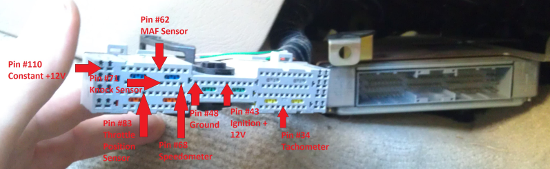
Just want some other users to double-check this list
2.brown goes to pin # 48 Ground
3.red AND 4.red/white stripe both go (1cm apart) to pin # 110 Constant +12v (not #112 or #43 for Ignition +12v??)
6.green goes to pin #34 Tachometer
14.yellow goes to pin #62 MAF sensor (closest to ecu where wire is cut)
5.white goes to pin #62 (other end of cut wire)
By my understanding I still need TPS... but my white wire is already used to MAF.
Would I use 10.grey for the TPS??
On the diagram, the color of the lines pointing to the ecu pinout are the colors for the afc harness.
bc the safc/emanage diagram shows
blue font for MAF
orange for constant power
From what I've read that is the trend... it's not a big deal either way to me.
I'm sorry if you took it to heart. But I REALLY doubt I am running lean so...
Last edited by NmexMAX; Jan 30, 2012 at 09:21 AM.
Soooo I guess hooking up this apexi n turning the **** to a random number will make things work huh lol.... I installed headers n my car ran leaner.... recipe for disaster here... to the OP before you go blind tuning I would suggest you actually go find out what ur AFR really is then go from there... do get the AFC hooked up but bro you don't know if the car is running rich....
Soooo I guess hooking up this apexi n turning the **** to a random number will make things work huh lol.... I installed headers n my car ran leaner.... recipe for disaster here... to the OP before you go blind tuning I would suggest you actually go find out what ur AFR really is then go from there... do get the AFC hooked up but bro you don't know if the car is running rich....
i'm not blind tuning.....
My point isn't to prove my hunch (<--- see, hunch... not actuality)...
it is to get the AFC hooked up and go from there but everyone keeps getting hung up that I said I was running rich.
GET OVER IT! I have a high performance shop w/a dyno tuning my maxima.
Just help me get the dang afc properly wired............
I looked through the diagram off apexi's site, but didn't see a vq35
I was curious what was used for reference.
Final check:
2.brown goes to pin # 48 Ground
3.red AND 4.red/white stripe both go (1cm apart) to pin # 110 Constant +12v (not #112 or #43 for Ignition +12v??)
6.green goes to pin #34 Tachometer
10.grey goes to pin #83 Throttle Position Sensor
14.yellow goes to pin #62 MAF sensor (closest to ecu where wire is cut)
5.white goes to pin #62 (other end of cut wire)
the vafcII or safc/emanage diagram?
Last question....
for clarification, I use the red & red/white stripe for pin #110 constant +12v
Nothing should be tapped on pin #43 for Ignition +12v
If there should be a wire, which one?
1.black
2.brown
3.red
4.red w/white stripe
5.white
6.green
7.purple
8.pink
9.orange
10.grey
11.black w/white stripe
12.brown w/ white stripe
13.blue
14.yellow
15.light pale green
these are already in use.
Last question....
for clarification, I use the red & red/white stripe for pin #110 constant +12v
Nothing should be tapped on pin #43 for Ignition +12v
If there should be a wire, which one?
1.black
2.brown
3.red
4.red w/white stripe
5.white
6.green
7.purple
8.pink
9.orange
10.grey
11.black w/white stripe
12.brown w/ white stripe
13.blue
14.yellow
15.light pale green
2.brown goes to pin # 48 Ground
3.red AND 4.red/white stripe both go (1cm apart) to pin # 110 Constant +12v (not #112 or #43 for Ignition +12v??)
6.green goes to pin #34 Tachometer
10.grey goes to pin #83 Throttle Position Sensor
14.yellow goes to pin #62 MAF sensor (closest to ecu where wire is cut)
5.white goes to pin #62 (other end of cut wire)
Doesn't matter, they're the same signals.
As far as colors, all you need to care about is the PDF link I provided for the colors corresponding to your NEO.
http://www.apexi-usa.com/manuals/ele...eo_diagram.pdf
Page 6.
You can use either or, (110/112) or (43).
As far as colors, all you need to care about is the PDF link I provided for the colors corresponding to your NEO.
http://www.apexi-usa.com/manuals/ele...eo_diagram.pdf
Page 6.
You can use either or, (110/112) or (43).

FINAL checklist:
black and brown both go (1cm apart) to pin # 48 Ground
red and red/white stripe both go (1cm apart) to pin # 110 Constant +12v
green goes to pin #34 Tachometer
grey goes to pin #83 Throttle Position Sensor
yellow goes to pin #62 MAF sensor (closest to ecu where wire is cut)
white goes to pin #62 (other end of cut wire)
purple goes to pin #71 Knock Sensor
http://www.apexi-usa.com/manuals/ele...eo_diagram.pdf
From page 9
The Apexi installation manual states that pin # is indicated by looking at ECU from side where the vehicle's harness plugs in. SO that would mean it was mirrored when you are examining the harness itself, correct?
Example:
Does this allow illumination as well?
I read on Apexi manual that orange wire (as typically I've ran into w/stereos) is for illumination.
Are any of the orange wires coming off ecu fair game??
FINAL checklist:
black and brown both go (1cm apart) to pin # 48 Ground
red and red/white stripe both go (1cm apart) to pin # 110 Constant +12v
green goes to pin #34 Tachometer
grey goes to pin #83 Throttle Position Sensor
yellow goes to pin #62 MAF sensor (closest to ecu where wire is cut)
white goes to pin #62 (other end of cut wire)
purple goes to pin #71 Knock Sensor
http://www.apexi-usa.com/manuals/ele...eo_diagram.pdf
From page 9
The Apexi installation manual states that pin # is indicated by looking at ECU from side where the vehicle's harness plugs in. SO that would mean it was mirrored when you are examining the harness itself, correct?
Example:

Does this allow illumination as well?
I read on Apexi manual that orange wire (as typically I've ran into w/stereos) is for illumination.
Are any of the orange wires coming off ecu fair game??
black and brown both go (1cm apart) to pin # 48 Ground
red and red/white stripe both go (1cm apart) to pin # 110 Constant +12v
green goes to pin #34 Tachometer
grey goes to pin #83 Throttle Position Sensor
yellow goes to pin #62 MAF sensor (closest to ecu where wire is cut)
white goes to pin #62 (other end of cut wire)
purple goes to pin #71 Knock Sensor
http://www.apexi-usa.com/manuals/ele...eo_diagram.pdf
From page 9
The Apexi installation manual states that pin # is indicated by looking at ECU from side where the vehicle's harness plugs in. SO that would mean it was mirrored when you are examining the harness itself, correct?
Example:
Does this allow illumination as well?
I read on Apexi manual that orange wire (as typically I've ran into w/stereos) is for illumination.
Are any of the orange wires coming off ecu fair game??
I'm not sure about illumination wire. My vafc2 had no such wire as far as I kno
I'm waiting until tomorrow on solder. everythings ready to put together and I have all the relearn procedures. Tomorrow should be an epic day

http://dbrhighperformance.com/cart_new/
Dyno Dynamics is the brand. No dynojet here.
http://dbrhighperformance.com/cart_n...yno-tuning.php
Dyno Dynamics is the brand. No dynojet here.
http://dbrhighperformance.com/cart_n...yno-tuning.php
Problem...
I think I did the install correct, but the tuner has yet to power on....
Also, it hasn't completed the MAF circuit as now car won't rev over 2200.
I checked my install twice... first time I was just trying to tape connections, but then I soldered all connections. So I'm still unsure where my problem is.
I am going to contact Apexi tomorrow to figure out how to test the tuner with a multimeter so I know that the unit is functional.
In the mean time, any suggestions?
I did ecu reset, and the 3 relearn procedures for idle, throttle position, etc.
I've never had a MAF problem, but from what I have read it is textbook of maf.
...bucks under load, won't rev over 2.2k..
My theory was that since I cut the MAF, it just can't read the signal...
maf signal should now be running THROUGH the neo. you clipped the wire. the end coming from the ECU should run to a wire. the end going to the engine bay goes to a different wire.
the issue your listing is maf related. double and triple check your maf wiring.
the issue your listing is maf related. double and triple check your maf wiring.