
A32 Adjustable Lower Control Arms


A32 Adjustable Lower Control Arms
The shop I asked to make the ALCAs started to machine and fabricate the parts for 4th gen lower ALCAs. Months ago I had sent them a set of used arms and told them I would want something with a corrected roll center, adjustable camber, and the ability to add some positive caster if possible. (Which the A32s need badly)
This is what he came up with so far
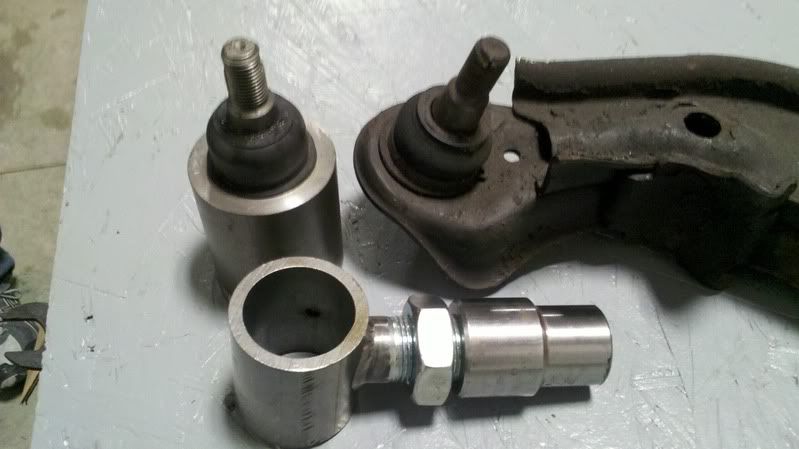
This design uses the OEM balljoints which are very sturdy and last a long time. A longer balljoint with spacers is a quick fix but ideally you want a short ball joint stud as it reduces flex & stress on the stud.
The thread adjusts in and out about an inch and this will allow adjustment of camber. These are designed to have more negative camber than stock and allow a bit more with the threaded adjuster. I have to measure the adjustment range when the prototype set is ready. You have to pop out the ball joint of the hub to adjust camber but once its set there is no need to worry about anything.
The idea is you can set your arms up and not have to worry about them until you need to replace the balljoints. Everything is heavy duty, the adjuster threads are 1" and rated well above the balljoint's strength. The cup and scalloped threaded rod is TIG welded to be very strong. The only drawback to this method is that the roll center is fixed and cannot be adjusted. These arms he is making for my car raise the roll center 1.5" and just clear my 17" rims. I will only have 1" of drop at most as the Koni/GC struts have limited suspension travel so these will work for me and still give me a better camber curve along with alot more negative static camber. If your slammed on coilovers and want more roll center correction you would have to run larger rims.
Most good race tires come in 17" and I don't have any issue with it. Guys who run 15s or 16s and want these ALCAs are out of luck. The A32s LCAs were designed around compact 15" rims with Macpherson struts and this is why the roll center and camber curve are so bad when lowered. They could not make the stock arms or knuckles sit any lower with 15" or 16" rims and a McStrut configuration provides very little negative camber gain.
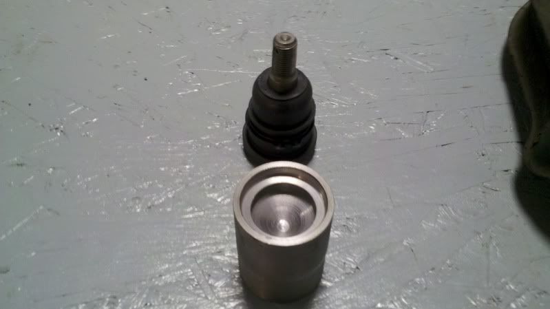
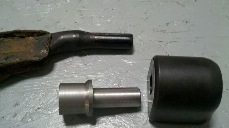
This is the custom made fitting tool to press in the ball joints. These have to be machined out of solid steel on his lathe but match the balljoint bottom perfectly. These will make replacing balljoints 5x easier with these custom roll center lifters.
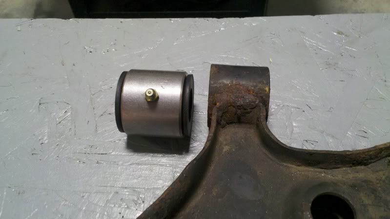
This is the piece that holds the front bushings. These were designed to work around ES bushings and that is why there is a grease fitting attached for easier greasing of the poly bushings. Extra options for this piece may involve a rod end and threaded adjuster for some caster adjustment or he could make these bushings out of delrin on his lathe.
The machined piece for the rear bushings. Again they are designed to work with ES or Superpro bushings and he could make this part out of delrin as well.
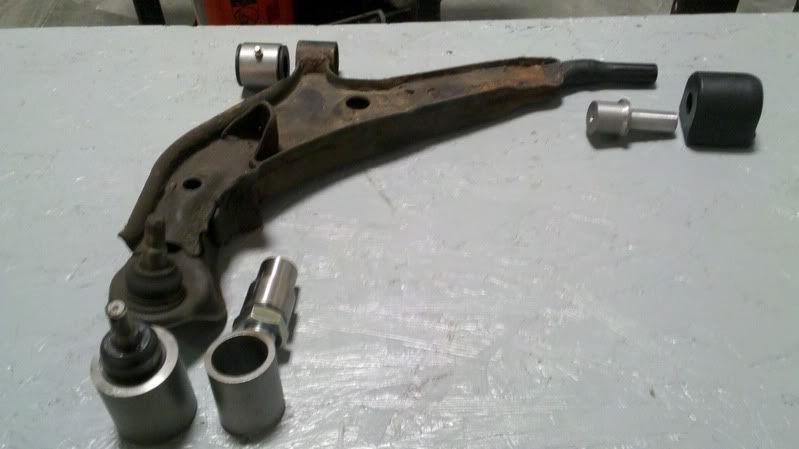
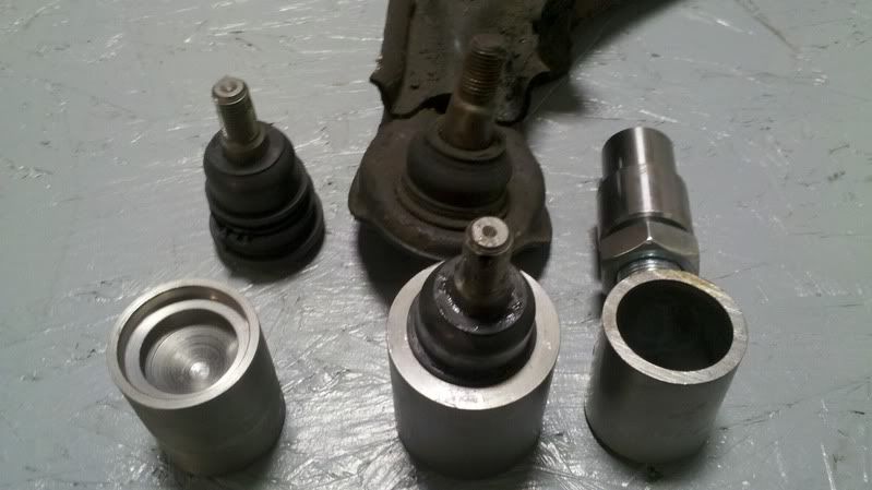
The whole setup as it sits now. His next step is to fabricate a set of welding jigs so he can weld all the tubing together and have me test fit these arms to see what changes have to be done, if any. Right now he has enough machined parts and steel tubing for my set and one more set if anyone is willing to put up the money.
I have paid for most of the R&D and will do all the testing myself. So the production sets should be less than what I paid but bear in mind it is one guy working on this stuff so it will take some time and its not some Chinese made copy cat of the crappy OEM LCAs.
This is what he came up with so far
This design uses the OEM balljoints which are very sturdy and last a long time. A longer balljoint with spacers is a quick fix but ideally you want a short ball joint stud as it reduces flex & stress on the stud.
The thread adjusts in and out about an inch and this will allow adjustment of camber. These are designed to have more negative camber than stock and allow a bit more with the threaded adjuster. I have to measure the adjustment range when the prototype set is ready. You have to pop out the ball joint of the hub to adjust camber but once its set there is no need to worry about anything.
The idea is you can set your arms up and not have to worry about them until you need to replace the balljoints. Everything is heavy duty, the adjuster threads are 1" and rated well above the balljoint's strength. The cup and scalloped threaded rod is TIG welded to be very strong. The only drawback to this method is that the roll center is fixed and cannot be adjusted. These arms he is making for my car raise the roll center 1.5" and just clear my 17" rims. I will only have 1" of drop at most as the Koni/GC struts have limited suspension travel so these will work for me and still give me a better camber curve along with alot more negative static camber. If your slammed on coilovers and want more roll center correction you would have to run larger rims.
Most good race tires come in 17" and I don't have any issue with it. Guys who run 15s or 16s and want these ALCAs are out of luck. The A32s LCAs were designed around compact 15" rims with Macpherson struts and this is why the roll center and camber curve are so bad when lowered. They could not make the stock arms or knuckles sit any lower with 15" or 16" rims and a McStrut configuration provides very little negative camber gain.
This is the custom made fitting tool to press in the ball joints. These have to be machined out of solid steel on his lathe but match the balljoint bottom perfectly. These will make replacing balljoints 5x easier with these custom roll center lifters.
This is the piece that holds the front bushings. These were designed to work around ES bushings and that is why there is a grease fitting attached for easier greasing of the poly bushings. Extra options for this piece may involve a rod end and threaded adjuster for some caster adjustment or he could make these bushings out of delrin on his lathe.
The machined piece for the rear bushings. Again they are designed to work with ES or Superpro bushings and he could make this part out of delrin as well.
The whole setup as it sits now. His next step is to fabricate a set of welding jigs so he can weld all the tubing together and have me test fit these arms to see what changes have to be done, if any. Right now he has enough machined parts and steel tubing for my set and one more set if anyone is willing to put up the money.
I have paid for most of the R&D and will do all the testing myself. So the production sets should be less than what I paid but bear in mind it is one guy working on this stuff so it will take some time and its not some Chinese made copy cat of the crappy OEM LCAs.
Last edited by 98SEBlackMax; Dec 19, 2010 at 12:55 PM.

Member
Joined: Jan 2009
Posts: 151
From: lawrenceville GA
Been waiting for someone to get serious with the a32 suspension setup this looks very promising. If you do production versions i maybe interested. Although i am on d2 coilovers and way more than 1 inch low.

Custom mounts for the spherical end links are also being considered along with making the sway bar adjustable. He can also include a mounting plate for those people using traction rods.
Obviously bump steer will also have to be corrected with these ALCAs but I already have a kit for bump adjustable outer tie rods.
Last edited by 98SEBlackMax; Dec 20, 2010 at 12:53 PM.


great project. always wanted to do something like this when i had my maxima.
spacing the ball joint up from the lca will not correct roll center. nothing you do with a stock ball joint will, since the angle is from the pivot point. spacers aren't a "quick fix", they are used to drop the joint down from the spindle which results in an actual change.
if it was my project i would have used heim joints and long tapered studs w/ optional spacers.

Will this help people who want to AutoX while dropped 3" or so? I know that the A32's suspension gets outta wack when you get that low and I've been wondering what needs to be done to help that...

great project. always wanted to do something like this when i had my maxima.
spacing the ball joint up from the lca will not correct roll center. nothing you do with a stock ball joint will, since the angle is from the pivot point. spacers aren't a "quick fix", they are used to drop the joint down from the spindle which results in an actual change.
if it was my project i would have used heim joints and long tapered studs w/ optional spacers.
spacing the ball joint up from the lca will not correct roll center. nothing you do with a stock ball joint will, since the angle is from the pivot point. spacers aren't a "quick fix", they are used to drop the joint down from the spindle which results in an actual change.
if it was my project i would have used heim joints and long tapered studs w/ optional spacers.
Yes lowering the pivot point would help the most with roll center but the length of the arms help to. Also the angle of the arms relative to the struts also helps with negative camber gain under roll. This is where the A32 suffers badly as there is poor camber gain when cornering, these arms will give more dynamic camber gain which would be more noticeable with reduced understeer.
However the design is still open to using rod ends with a tapered studs with spacers, its that we did not want to have something that wears so quickly and needs maintenance. Also the longer stud has the greater potential to bend or break easier.
I just got off the phone talk ith this guy and he had mentioned that for mostly tracked cars he could make a rod end/tapered stud/spacer setup. He has made ALCAs for other cars and people always *****ed about rod ends wearing out, so his thought was to make these much more user friendly with less maintenance. I may try the existing setup and see how it feels and if I need something more I could convert later on.
Last edited by 98SEBlackMax; Dec 20, 2010 at 12:58 PM.

Joe, he's correct on that point.
moving the entire ball joint up doesn't do anything REAL in relation to the control arm angle. you just make the control arm an L shape instead of lowering the actual pivot point.
I ran into this several years ago when I started with this whole deal on my 3 gen.
Yes, you'll see a slight difference in roll center and track width because the angle across the L is longer than the original control arm. But you're not doing anything about changing the pivot points. the pivot point is still 2" below the bottom of the knuckle- you just moved the entire knuckle out a fraction of an inch, which now changes your ackerman since the steering rack pivots didn't move but you moved the steering axis since the knuckle is moved. whole-nuther ball of wax.

The only proper way to move the roll center is to lower the outer pivot point itself in relation to the wheel hub (which is attached to the steering knuckle). that requires that you either modify the knuckle by lowering the mounting point (i.e. weld onto cast steel), or that you use an extended tapered shank and a monoball bearing/rod end on the end of the control arm.
moving the entire ball joint up doesn't do anything REAL in relation to the control arm angle. you just make the control arm an L shape instead of lowering the actual pivot point.
I ran into this several years ago when I started with this whole deal on my 3 gen.
Yes, you'll see a slight difference in roll center and track width because the angle across the L is longer than the original control arm. But you're not doing anything about changing the pivot points. the pivot point is still 2" below the bottom of the knuckle- you just moved the entire knuckle out a fraction of an inch, which now changes your ackerman since the steering rack pivots didn't move but you moved the steering axis since the knuckle is moved. whole-nuther ball of wax.
The only proper way to move the roll center is to lower the outer pivot point itself in relation to the wheel hub (which is attached to the steering knuckle). that requires that you either modify the knuckle by lowering the mounting point (i.e. weld onto cast steel), or that you use an extended tapered shank and a monoball bearing/rod end on the end of the control arm.
Fair enough, I can run a longer rod end/taper with a spacer.
Now in your diagram what if the car was lowered and the angle of the control arm sat the other way? Most lowered Maximas I've seen the inner parts of the control arms sit lower than the outer part, would it help to lower the outer part of the control arms?
Also do you ever find a tapered shank that would work for us? I could have the hubs drilled out to accept a different taper but if there was a longer balljoint made for Nissans that would be great.
Last edited by 98SEBlackMax; Dec 20, 2010 at 01:20 PM.

The only one I ever found to fit was the ones that SPL sells with their front control arms for Z and S chassis cars. But he only sells those as a complete kit w/ the control arm.
Your best bet for an affordable 1-off part is to buy a chevy/ford tapering tool and regrind the taper to fit a domestic app, then buy studs from a company that sells parts for them- like Rod End Supply or Coleman Machine..
As for the angles, I'm fully aware of the geometry issues. The options are to:
1. lower the outer joint by modifying the knuckle to move the factory ball joint mount down.
2. lower the outer joint by using a longer ball joint shank as we're discussing.
3. raise the inner control arm pivot points. this is going to be nearly impossible on a Maxima due to the location of the pivots.
4. Raise the car. having a low center of gravity means nothing if the damn thing can't handle because of the geometry (and runs out of suspension travel as well.)
Option 4 is the least expensive. option 2 is next and is what most people choose.
fortunately my S14 has enough space that I can raise the mounting points on the front control arms and TC rods without much trouble.
Last edited by bryan163; Dec 20, 2010 at 09:06 PM.
got to be careful with those "roll center adjuster" ball joints as a lot of them are just regular bj's with riser bases. the real deal have longer shanks. moonface makes some legit versions that may work (z32/s13/s14/r32), it's just a matter of measuring.
another method i've seen used instead of tapered shanks is drilling the taper out of the knuckle and using regular studs.
another method i've seen used instead of tapered shanks is drilling the taper out of the knuckle and using regular studs.

Going with a generic tapered ball joint stud using heim joints and reaming the hubs to accept a different taper. Trying to get the outer ball joint pivot point to sit as low as possible without hitting the inside of the rims.
The other option was to machine a rod of tool steel to make a a ball stud and having it heat treated, but it is to much risk. It would be easier to buy an off the shelf part that is already made for it and ream the stock hubs to match.
The other option was to machine a rod of tool steel to make a a ball stud and having it heat treated, but it is to much risk. It would be easier to buy an off the shelf part that is already made for it and ream the stock hubs to match.


Most of it looks good, very interested. Just don't like that it doesn't change the location of the ball joint pivot. That's the biggest reason to need a new control arm design!
http://www.nittotire.com/blog_detail.asp?id=15


not sure which shop did this, but it has been done for the Sentra community. if only someone here was buddies with Mike Kojima.
not sure which shop did this, but it has been done for the Sentra community. if only someone here was buddies with Mike Kojima.
you don't want to do it that way on a street car. on a track only car, sure. but to put that much stress on a rod end on a street car is asking for trouble- especially in a heavy FWD car.
Rod ends are made for tension and compression; they are NOT made for bending loads.
Rod ends are made for tension and compression; they are NOT made for bending loads.
http://www.nittotire.com/blog_detail.asp?id=15
not sure which shop did this, but it has been done for the Sentra community. if only someone here was buddies with Mike Kojima.
not sure which shop did this, but it has been done for the Sentra community. if only someone here was buddies with Mike Kojima.
you don't want to do it that way on a street car. on a track only car, sure. but to put that much stress on a rod end on a street car is asking for trouble- especially in a heavy FWD car.
Rod ends are made for tension and compression; they are NOT made for bending loads.
Rod ends are made for tension and compression; they are NOT made for bending loads.


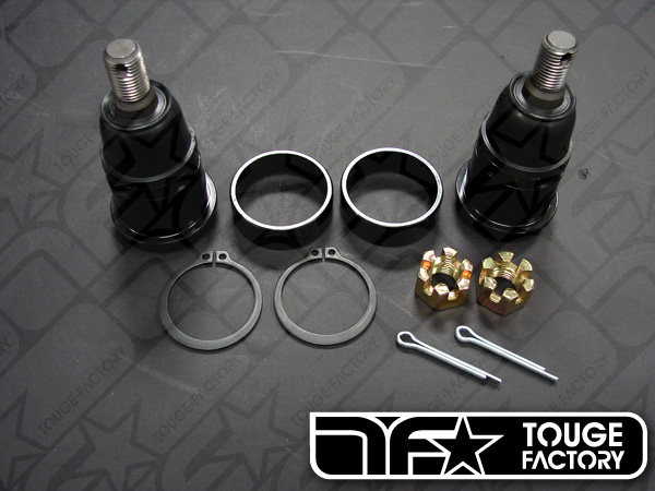
Something like this seems more reasonable. OEM makes these for the B14s but I haven't heard much feed back yet. The custom tapered stud they made for this project might work in a A32 spindle. I talked to Mark about it and he could look into making something for me however after the camber/caster plate issue I am not so confident.
Last edited by 98SEBlackMax; Jan 27, 2011 at 01:20 PM.

 those sentra ******* have everything.
They also have alot more people willing to spend the time and money on suspension parts. 
Some of the stuff I have is B14 suspension parts modified to work on my car.
However that Sentra stuff can be cheap and not well engineered. For example it might be me or my computer monitor but I swear that sway bar end link tab isn't welded onto that ACLA very straight.
Some of the stuff I have is B14 suspension parts modified to work on my car.
However that Sentra stuff can be cheap and not well engineered. For example it might be me or my computer monitor but I swear that sway bar end link tab isn't welded onto that ACLA very straight.
Last edited by 98SEBlackMax; Jan 27, 2011 at 01:23 PM.
you don't want to do it that way on a street car. on a track only car, sure. but to put that much stress on a rod end on a street car is asking for trouble- especially in a heavy FWD car.
Rod ends are made for tension and compression; they are NOT made for bending loads.
Rod ends are made for tension and compression; they are NOT made for bending loads.
In the case of braking and accelerating, the force would not be compression or tension for the threaded rod end shaft, it would be perpendicular. From a quick search, braking forces in typical sports cars are 1-1.5 g, which means a load of approximately 1500-2250 lbs for each side of a 3000 lb car. For a part like ARHT8CR the threaded part is 5/8 of an inch for a 1/2 ball bore. It is rated at 21,800 static. Now I realize that's a static rating, but there is a safety factor of 7 for a 3000 lb car to do 1g of braking with only one tire. If shearing the stud is your concern, those rod ends are 17-4PH stainless and have a tensile strength of 160-190ksi.
For cornering, you'd be lucky to get near 1g in a turn with a maxima, and that force is spread over multiple tires.
I'm also thinking the rod end should be angled in such a way that when the suspension is at rest at the desired ride height, the threaded shaft of the rod end would be perpendicular to the tapered stud inserted into the knuckle. You can see this especially well in the picture Joe posted. Notice the LCA is level with the ground, but the tapered stud leaves the knuckle at an angle that is not perpendicular to the ground, causing the ball in the rod end to not be in the center of its range of motion. This is not ideal. If the rod end was angled up slightly from left to right, the axial forces on the ball in the rod end would be minimized if the assertion in the paragraph above is correct.
Thoughts?
Agreed to an extent as far as axial force goes. I think the front sway bar would contribute to the up and down load on the ball joint/rod end. If you had a disconnected or removed front sway bar, then I agree that the load would be minimal.
I also agree that the ball in the rod end should be close to center. the nittotire picture above is at full droop so i'm sure that once it settled with weight on it, it would look more like 98SEBlackMax's picture.
I also agree that the ball in the rod end should be close to center. the nittotire picture above is at full droop so i'm sure that once it settled with weight on it, it would look more like 98SEBlackMax's picture.
This site sells the "racing" series, but they are expensive. According to the site, the NHBB rod ends are the best and find themselves on F-1, NASCAR, and CART cars. They also have neat boots and seals for rod ends on the rod end accessories page.
safety factor of 7? How much force do you think the suspension undergoes when you hit a pothole? it's enough to bend a wheel and blow a tire many times, so how much do you think that relates to force on the control arm? it's way more than 7x the expected load.
Do some research in "rod end in bending" and you'll find it's a naughty thing in the world of engineering. the proper way to do it would be to use a spherical bearing with a reinforced housing on the outer joint, like this one:

The inner joint on that control arm can only be loaded in tension or compression, so a rod end there is just fine.
So if one were so inclined, they could machine a piece from steel that would weld to the end of the LCA. This piece would hold a spherical bearing at an angle complementary to the angle that the tapered shaft exits the knuckle, keeping the ball at 0* misalignment at ride height.
Do you think the design could be so simple as to include a piece of thick wall tubing with the ID machined to accept the spherical bearing? If tubing with the proper dimensions was found, could it just be welded to the end of a stock LCA, taking care that the welds are strong and there is sufficient material to handle the loads?
That's exactly what you could do. That steel is readily available from race suspension shops already- like Coleman, AED Motorsports, etc. The only problem with that is the stock control arm will likely have to be lengthened to make this work- so cutting and welding may be a bit more complicated than that.
One other thing to keep in mind though is that the 3 gen control arm uses a bolt-on ball joint, as does the 280ZX and some others.. http://shopping.yahoo.com/nissan-ball-joints--shop/
If the 3 gen arm would bolt into the factory mounting locations on a 4/5 gen, it's possible to fabricate a bolt-on adjustable ball joint w/ heim and stud vs. chopping the end of a 4/5 gen control arm off and making something to fit.
It's yet another option to think about.

got to be careful with those "roll center adjuster" ball joints as a lot of them are just regular bj's with riser bases. the real deal have longer shanks. moonface makes some legit versions that may work (z32/s13/s14/r32), it's just a matter of measuring.
another method i've seen used instead of tapered shanks is drilling the taper out of the knuckle and using regular studs.
another method i've seen used instead of tapered shanks is drilling the taper out of the knuckle and using regular studs.
S13 Front
Taper low diameter 15.8mm
Taper High diameter 18mm
Taper length 19.5mm
Diameter where it presses in 41mm
S13 Rear, R32 Rear
Taper low diameter 15mm
Taper High diameter 18.6mm
Taper length 23mm
Diameter where it presses in 38mm
R32 Front. S14 F&R , S15 F&R
Taper low diameter 15mm
Taper High diameter 18.6mm
Taper length 23mm
Diameter where it presses in 41mm
anyone have any Maxima ball joint dimensions???
Bump. Did you ever get those measurements?
Another thing.... Can we make a custom spindle to achieve the same effect? EG making a slightly taller spindle to correct roll center? I'd also want to have bolt up hubs like newer nissans too....
Another thing.... Can we make a custom spindle to achieve the same effect? EG making a slightly taller spindle to correct roll center? I'd also want to have bolt up hubs like newer nissans too....

