

VTC Cam Angles vs RPM

Thread Starter

Joined: Oct 2002
Posts: 1,199
From: Ontario, Canada
VTC Cam Angles vs RPM
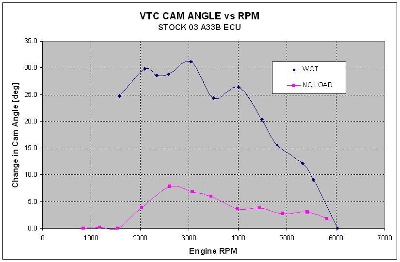
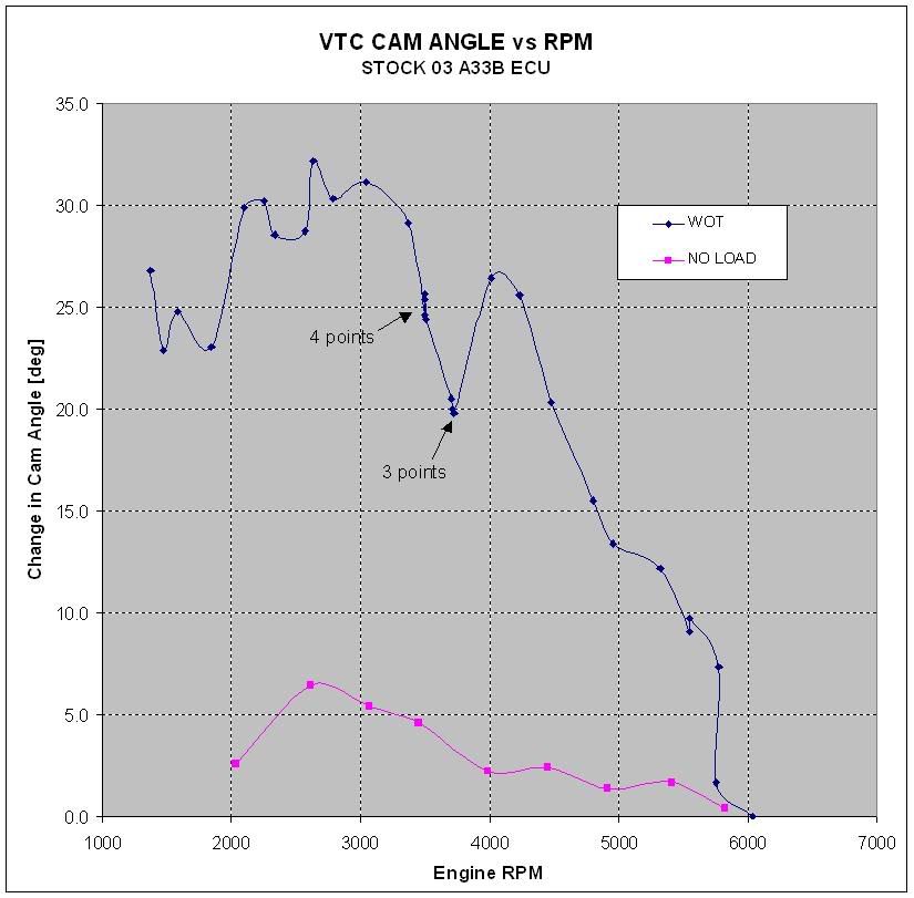
The data in the graph below was obtained by scoping the crank and cam signals at various rpm points and measuring the timing changes between them. The overall range of approximately 0-30 degrees is in good agreement with what is stated in the FSM.
EDIT - Before anyone rags on me - The y-axis should designate CRANK angle - NOT CAM angle
The cams in the 287hp Z33 are the same and it also has the same 30 deg crank angle range. The difference (if any) would have to be the slope of the ramp down from 30 degrees and what rpm level they are brought back to 0 degrees at.
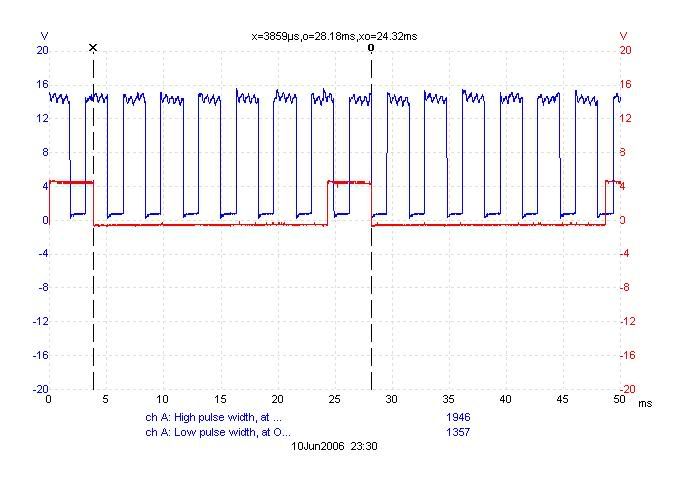
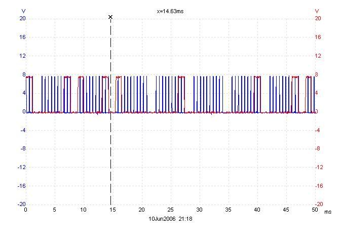
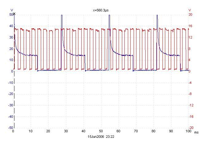
The vtc solenoid pulse signal is displayed below in blue with the ignition signal to one of the coils in red for a relative frequency comparison. Data was taken at WOT at approximately 5Krpm.
EDIT - Before anyone rags on me - The y-axis should designate CRANK angle - NOT CAM angle
The cams in the 287hp Z33 are the same and it also has the same 30 deg crank angle range. The difference (if any) would have to be the slope of the ramp down from 30 degrees and what rpm level they are brought back to 0 degrees at.
The vtc solenoid pulse signal is displayed below in blue with the ignition signal to one of the coils in red for a relative frequency comparison. Data was taken at WOT at approximately 5Krpm.

Thread Starter
Joined: Oct 2002
Posts: 1,199
From: Ontario, Canada
Top waveforms are crank and cam signals at about 6200 rpm (VTC solenoids are no longer being pulsed)
Crank is blue. Cam is red.
Bottom waveforms are at about 3000 rpm. The cam is approximately 30 degrees advanced relative to the crank.
 ]
]The graphs above will probably only make sense to someone who is very familiar with the crank and cam signal wheels.
Thread Starter
Joined: Oct 2002
Posts: 1,199
From: Ontario, Canada
Originally Posted by SR20DEN
The VTC gears are supposed to have a maxium sweep of 40�.
Originally Posted by SR20DEN
So how did you monitor the actual cam offset, in relation to the RPM and pulse?
I was not too concerned with the pulse signal this time around. However from the waveforms above, you can see that the "ON" time is shorter than the "OFF" time which indicates that the cams are being retarded which is what is expected at 5K.
Thread Starter
Joined: Oct 2002
Posts: 1,199
From: Ontario, Canada
Originally Posted by SR20DEN
Interesting. So the crank signals are reading the gaps as pulses and the cam signals are reading the lobes. Odd.
Do you have longer graphs? I take it you've actually seen the cam pickups.
Do you have longer graphs? I take it you've actually seen the cam pickups.
Originally Posted by eng92
No they both read the gaps. You have to think of the linear velocity of the crank signal plate vs that of the cam. The speed at which the gap passes the sensor is proportional to the diameter. Also, the crank is turning at twice the angular speed.
Thread Starter
Joined: Oct 2002
Posts: 1,199
From: Ontario, Canada
Originally Posted by SR20DEN
Which is why i asked for a longer graph, to see the bigger picture. (one full cam rotation). Which should equal six of the crank reference pauses.
Thread Starter
Joined: Oct 2002
Posts: 1,199
From: Ontario, Canada
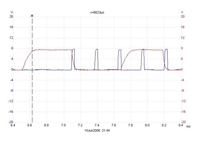
This is about 1-1/3 crank rotations at idle.
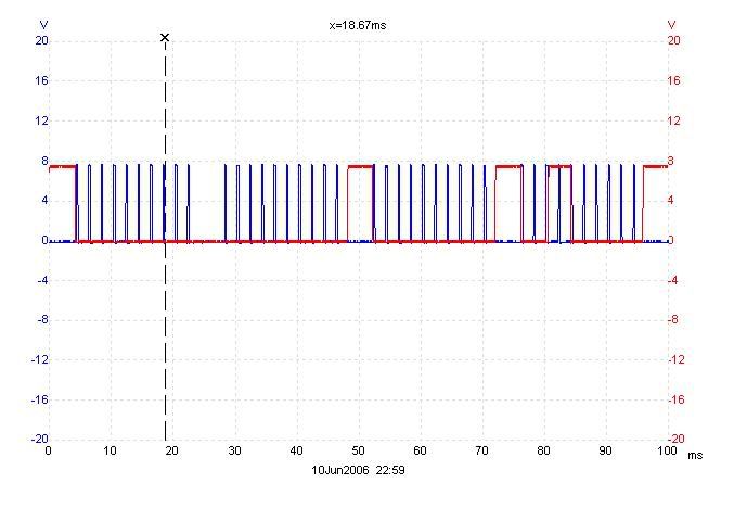
As the measurements are essentially taken from screen shots, I have better accuracy if I use a smaller time scale.
As the measurements are essentially taken from screen shots, I have better accuracy if I use a smaller time scale.
Thread Starter
Joined: Oct 2002
Posts: 1,199
From: Ontario, Canada
Originally Posted by DandyMax
Nice work Dave; good info. Will have to look at this again more when I'm not falling asleep.
Originally Posted by eng92
My FSM shows an expected operating range of approximately 0-30 degrees when revved from idle to 2K.
The Nismo VTCs are advertised at 55� (crank) which is of course 27.5� (cam), and I have seen them listed as being an additional 15� (crank) over the OE VTCs.
Now I think it would be cool watch the cam pickup with a tiny camera, strobed with an ignition timing light to see it in action.
Thread Starter
Joined: Oct 2002
Posts: 1,199
From: Ontario, Canada
The FSM indicates that at idle, the cam timing should be in the range -5 to 5 crank degrees and 0 to 30 degrees at higher rpms. That gets us a little closer at 35 degrees total.
Also, it is quite possible that the IVT control maps are set up to keep the vtc working within its range so it is not driven up against a hard stop at either end of its travel.
Also, it is quite possible that the IVT control maps are set up to keep the vtc working within its range so it is not driven up against a hard stop at either end of its travel.
It is designed so that one lobe hits it's mechanical limit before the other three do, which gives the others plenty of chamber space to be filled with oil and backed out. And it can be backed up with simple parasitic drag of the cam.
Full retard, as it is in the locked position, the master control lobe is pushed against it's stop.
Full retard, as it is in the locked position, the master control lobe is pushed against it's stop.
Thread Starter
Joined: Oct 2002
Posts: 1,199
From: Ontario, Canada
Originally Posted by IceY2K1
Know anyone with a Z33/G35 you could test?
It is kind of amusing really. Instead of civics, all I see are sunfires and cavaliers with the huge spoilers and the fartcan mufflers to match.
Thread Starter
Joined: Oct 2002
Posts: 1,199
From: Ontario, Canada
You will have to wait on Vasily for that one.
With some off the shelf components and a little bit of electronic creativity, one can create their own independent VTC controller with feedback. All the necessary sensor inputs are already present and I know what form the required outputs need to be. I just need to build a little black box to make the magic happen.
With some off the shelf components and a little bit of electronic creativity, one can create their own independent VTC controller with feedback. All the necessary sensor inputs are already present and I know what form the required outputs need to be. I just need to build a little black box to make the magic happen.
Originally Posted by eng92
You will have to wait on Vasily for that one.
With some off the shelf components and a little bit of electronic creativity, one can create their own independent VTC controller with feedback. All the necessary sensor inputs are already present and I know what form the required outputs need to be. I just need to build a little black box to make the magic happen.
With some off the shelf components and a little bit of electronic creativity, one can create their own independent VTC controller with feedback. All the necessary sensor inputs are already present and I know what form the required outputs need to be. I just need to build a little black box to make the magic happen.
My method is going to be a litte more crude than yours. I want to set mine up to sever the ECU link @ 90% throttle so I can write my own map with the EU during the remaining 10%.
Thread Starter
Joined: Oct 2002
Posts: 1,199
From: Ontario, Canada
Originally Posted by SR20DEN
I think a feedback box would be great to interface with a EB or EU, so those devices can be used to control the VTC solenoids, via additional injector drivers.
My method is going to be a litte more crude than yours. I want to set mine up to sever the ECU link @ 90% throttle so I can write my own map with the EU during the remaining 10%.
My method is going to be a litte more crude than yours. I want to set mine up to sever the ECU link @ 90% throttle so I can write my own map with the EU during the remaining 10%.
I was thinking along your lines initially with using a relay energized at >90% throttle to switch the VTC solenoid grounds between the ecu and an external controller.
Now that I can monitor the crank and cam positions directly, I will do a little bit of experimentation first using the EU as an open loop VTC controller. I do not have any experience with pwm solenoids so I am a little concerned about trying to operate them with such a reduced frequency signal (especially at lower rpms)
A feature on the EU that might be useful, but not sure....
1)Set CHA/CHB to activate per CH1-CH6 and use the timing offset.
Maybe using these in some way or combining the two channels together to operate both VTC solenoids might be a way around the low PWM signal when using injector maps to drive them.

1)Set CHA/CHB to activate per CH1-CH6 and use the timing offset.
Maybe using these in some way or combining the two channels together to operate both VTC solenoids might be a way around the low PWM signal when using injector maps to drive them.
Thread Starter
Joined: Oct 2002
Posts: 1,199
From: Ontario, Canada
Originally Posted by IceY2K1
A couple things about on the EU that might be useful, but not sure....
1)Try using CHA/CHB Sub I/J channels set with "Type" and set to "RPM".
or
2)Set CHA/CHB to activate per CH1-CH6 and use the timing offset.
1)Try using CHA/CHB Sub I/J channels set with "Type" and set to "RPM".
or
2)Set CHA/CHB to activate per CH1-CH6 and use the timing offset.
Option 2) would only give 1 pulse every 2 rpm.
What if you paired the injector wires to the EU and change the # of Input to 3 and the # of Output to 6, so you get....
Ch1/Ch6
1-0
1-120
1-240
1-360
1-480
1-600
2-0
2-120
2-240
2-360
2-480
2-600
3-0
3-120
3-240
3-360
3-480
3-600
Ch1/Ch6
1-0
1-120
1-240
1-360
1-480
1-600
2-0
2-120
2-240
2-360
2-480
2-600
3-0
3-120
3-240
3-360
3-480
3-600
Originally Posted by eng92
Possibly option 1) if the three pulses every 2 rpm are at equal spaced time intervals (240 degrees apart). Unfortunately there are no timing options with this setting otherwise you might be able to combine the 2 channels to get 6 pulses.
Thread Starter
Joined: Oct 2002
Posts: 1,199
From: Ontario, Canada
Originally Posted by IceY2K1
What if you paired the injector wires to the EU and change the # of Input to 3 and the # of Output to 6, so you get....
Ch1/Ch6
1-0
1-120
1-240
1-360
1-480
1-600
2-0
2-120
2-240
2-360
2-480
2-600
3-0
3-120
3-240
3-360
3-480
3-600
Ch1/Ch6
1-0
1-120
1-240
1-360
1-480
1-600
2-0
2-120
2-240
2-360
2-480
2-600
3-0
3-120
3-240
3-360
3-480
3-600
So on a V6 wouldn't 1-0 = 2-120 = 3-240 ?
What I'm trying to do is pick your brain or I'm hoping SR20DEN chimes in since he knows more about injection/ignition timing events then I do, how we can somehow combine the 6-inputs from the ECU to the 8-channel outputs from the EU.
Basically, we need to still fire the CH1-CH6 sequentially, but somehow incorporate the CHA/CHB to fire more often for the VTC solenoids when in RPM mode. Just wondering if it is possible to keep the order/timing, yet combine the inputs so the EU fires the injector outputs more frequently and out of phase by the correct amount.
Just brainstorming...I need to do some digging/reading, since I don't understand the timing events clearly.
Guest
Posts: n/a
the way I understand it the EU can fire the 7th and 8th outputs as 2 extra injectors. Which would mean you could fire them as much as you want anywhere in the rpm range as they would be mounted in the intake plenum. VTCs would use these 2 injector drivers, with a "fuel map" with a strange shape. But thats just an outsiders view...
~Alex
~Alex
Thread Starter
Joined: Oct 2002
Posts: 1,199
From: Ontario, Canada
I just wanted to make sure that we are all on the same page in terms of control of the VTC solenoids.
If this is a repeat for some of you, you can put your head down and have a nap.
Below is a picture I marked up out of one of my vendor's catalogs. It clearly illustrates the three types of pulses needed for control of pwm solenoid valves.
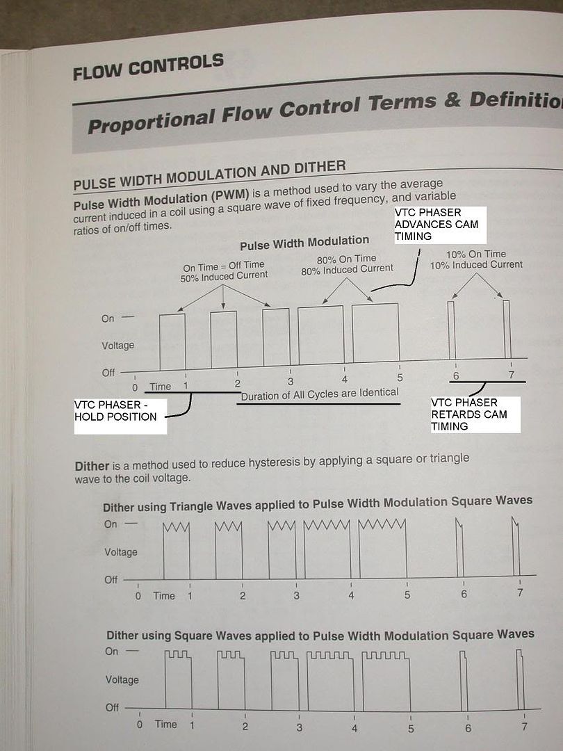
It is actually the inverse of my vtc solenoid waveforms as the ON pulse occurs when it is grounded (ie 0 volts)
You can see the dithering waveform present in the scope screenshot I posted previously. This keeps the valve oscillating a very small amount to prevent it from sticking. It also significantly reduces positional errors due to hysteresis (equal advance and retraction pulses not ending up at the same spot)
In terms of pulse duty cycle:
DC > 50% advance cam
DC = 50% hold cam position
DC < 50% retard cam
To use the EU for control, you have 16 different rpm points available in any injector map. In order to use intermediate cam positions, you would need to use adjacent columns with rpm points that are very close to one another. The left column would be to advance or retard and the right would be to hold. The rpm difference required will need to be experimented with as I currently do not know how long it takes the vtc to move full stroke.
Wait a minute, what is going to happen when you shift? Presumably, you will be up near redline and the cam is pretty well fully retarded and you shift but you need to get the cam to go back completely the other way and start retarding again. I guess some judicious choices have to be made when choosing rpms. If the leftmost column is selected at an rpm that will always be below your landing rpm when you shift then you can set it to >50% DC. The column immediately adjacent to that would need to set at 50% and at an rpm that is always above your shift landing rpm.
You can buy pwm solenoid valve drivers that you can adjust frequency and already have built in dithering functions. As input, some of them take an analog voltage or current. Varying the input changes the duty cycle of the output. I will have to see if I can find some cost effective units.
-EDIT- IceY2K1, This was not in response to your post. I started typing over an hour ago and got called away on something else.
If this is a repeat for some of you, you can put your head down and have a nap.
Below is a picture I marked up out of one of my vendor's catalogs. It clearly illustrates the three types of pulses needed for control of pwm solenoid valves.
It is actually the inverse of my vtc solenoid waveforms as the ON pulse occurs when it is grounded (ie 0 volts)
You can see the dithering waveform present in the scope screenshot I posted previously. This keeps the valve oscillating a very small amount to prevent it from sticking. It also significantly reduces positional errors due to hysteresis (equal advance and retraction pulses not ending up at the same spot)
In terms of pulse duty cycle:
DC > 50% advance cam
DC = 50% hold cam position
DC < 50% retard cam
To use the EU for control, you have 16 different rpm points available in any injector map. In order to use intermediate cam positions, you would need to use adjacent columns with rpm points that are very close to one another. The left column would be to advance or retard and the right would be to hold. The rpm difference required will need to be experimented with as I currently do not know how long it takes the vtc to move full stroke.
Wait a minute, what is going to happen when you shift? Presumably, you will be up near redline and the cam is pretty well fully retarded and you shift but you need to get the cam to go back completely the other way and start retarding again. I guess some judicious choices have to be made when choosing rpms. If the leftmost column is selected at an rpm that will always be below your landing rpm when you shift then you can set it to >50% DC. The column immediately adjacent to that would need to set at 50% and at an rpm that is always above your shift landing rpm.
You can buy pwm solenoid valve drivers that you can adjust frequency and already have built in dithering functions. As input, some of them take an analog voltage or current. Varying the input changes the duty cycle of the output. I will have to see if I can find some cost effective units.
-EDIT- IceY2K1, This was not in response to your post. I started typing over an hour ago and got called away on something else.
Thread Starter
Joined: Oct 2002
Posts: 1,199
From: Ontario, Canada
Originally Posted by Alex_V
the way I understand it the EU can fire the 7th and 8th outputs as 2 extra injectors. Which would mean you could fire them as much as you want anywhere in the rpm range
So, assuming the EU injector pulse type will work, the Sub injectors at 100% duty cycle would be equivalent to 50% PWM.
That could at least hold the cam angle when the ECU backs down to zero by 6000rpm, correct?
That could at least hold the cam angle when the ECU backs down to zero by 6000rpm, correct?
Thread Starter
Joined: Oct 2002
Posts: 1,199
From: Ontario, Canada
1 crank rotation at 6000 rpm takes 10ms. In the context of an injector which is based on 2 crank rotations, 100% duty is 20ms.
To hold position at 6K, the on/off pulses would be equal at 10ms (50% duty)
At SR20DEN's 7.5K redline, 50% duty would be 8ms.
The problem would be more at lower rpms because the pulses at a given DC become longer. At 3K, 50% duty is 20ms which is the upper limit for IPW with the EU.
This may be a concern at the lowest rpm in the map because you want a high ON pulse width in order to advance the cams as quickly as possible after your shift.
Of course this is assuming that you would be making the VTC maps for rpms from roughly 3-4K+ where the stock ecu starts to retard the cams.
Thread Starter
Joined: Oct 2002
Posts: 1,199
From: Ontario, Canada
Just a re-post of the graph from post#1 with some more data points added.
I did several more logs in the 3.5-3.75K region because the dip in the first data set looked suspicious. I did four independent data logs at 3500 rpm and they were all within 1.2 degrees. The three data points at 3750 were within 0.7 degrees so I guess the dip is real.
I can't quite explain why the cam would be retarded over a 500 rpm range and then advanced again.
Maybe it has something to do with working in conjunction with the VIAS
Originally Posted by eng92
J
I can't quite explain why the cam would be retarded over a 500 rpm range and then advanced again.
Maybe it has something to do with working in conjunction with the VIAS
I can't quite explain why the cam would be retarded over a 500 rpm range and then advanced again.
Maybe it has something to do with working in conjunction with the VIAS
But now we (I) need you to take measurments with a greatly reduced MAF voltage. You don't have to swap out injectors with the EU. You can cheat by using the additional injection map, effectively making the injectors larger.
Thread Starter
Joined: Oct 2002
Posts: 1,199
From: Ontario, Canada
Originally Posted by SR20DEN
That is exactly what it is.
But now we (I) need you to take measurments with a greatly reduced MAF voltage. You don't have to swap out injectors with the EU. You can cheat by using the additional injection map, effectively making the injectors larger.
But now we (I) need you to take measurments with a greatly reduced MAF voltage. You don't have to swap out injectors with the EU. You can cheat by using the additional injection map, effectively making the injectors larger.
Scratch that. Now I remember. You are running larger injectors with the scaled back MAF to bump your ignition timing.
That may have to wait for a little bit. I have not been running my injectors through the EU for a while. It runs quite rich (~10-10.5:1) at idle and I was not satisfied with the recommended solution that had no explanation. My input and output IPW is the same on my data logs so I am not quite sure where that problem lies. The only obvious thing I can think of is that one injector is grounding out in my EU harness somewhere.
Back on topic:
As far as the ecu is concerned, if you can snap the throttle open to say 50-60% to go into open loop, what is the difference? The ecu sees a reduced MAF and the only other difference that I can think of is the throttle position.
Can I not just stick a block under my pedal to simulate this or does the ecu need to see that WOT TPS as well?
What % reduction in MAF voltage are we taking about?
Thread Starter
Joined: Oct 2002
Posts: 1,199
From: Ontario, Canada
Originally Posted by SR20DEN
But now we (I) need you to take measurments with a greatly reduced MAF voltage.
A couple of years ago I was experimenting with my ignition timing and what the impact of engine load had on it. At the time I didn't have any equipment to change MAF voltage, all I had was an OBD-II scanner to monitor timing.
I was amazed how much of the filter I had to cover up before I could feel and measure a difference.
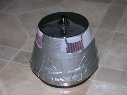
The duct tape is wrapped around a piece of plastic. It is not stuck to the filter.
Thread Starter
Joined: Oct 2002
Posts: 1,199
From: Ontario, Canada
Well I have had some preliminary success with VTC control using the EU sub-injector maps. It appears that the 50% duty cycle balance point doesn't mean squat when you are using such a low frequency to drive the solenoids.
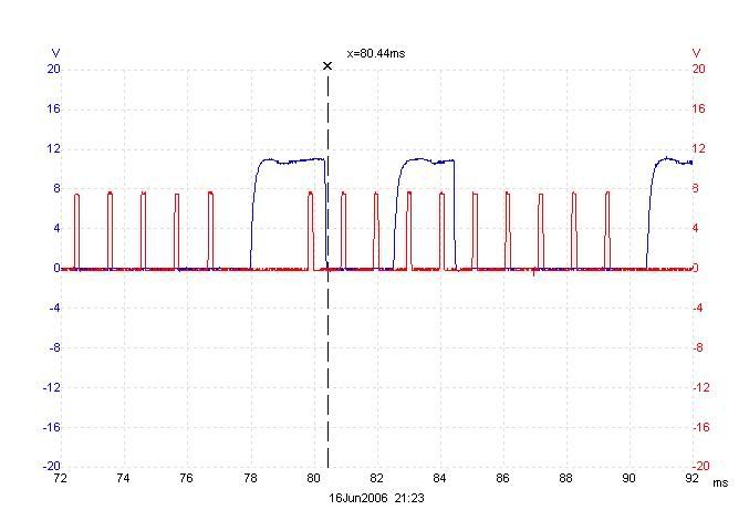
Here is a comparison of the PWM VTC waveform generated by the ecu (red) with the EU sub injector output (blue) This data was taken at around 2000 rpm.
20ms is the longest pulse width duration the EU will allow you to enter in an injector map. At 2000 rpm, this would only correspond to an IDC of 33%.
Yet by 2K, my intake cam was fully advanced at approximately 40 degrees over the VTC off condition. (Yes I found another 5 degrees of cam retard compared with the idle values I measured earlier.)
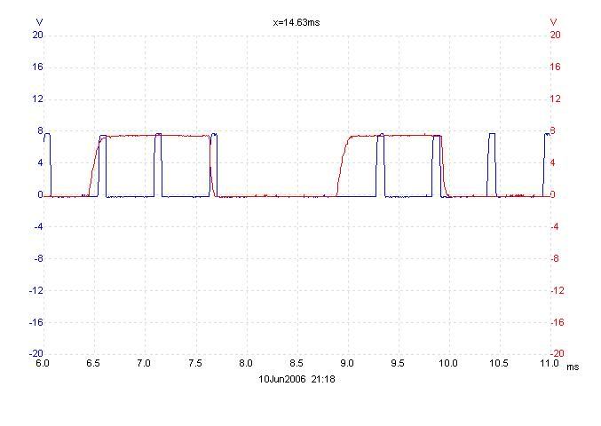
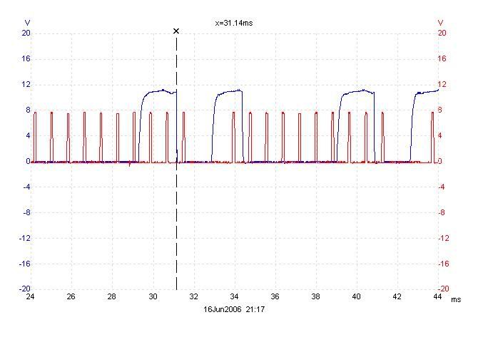
Here are two crank (red) and cam (blue) data sets taken at 1500 rpm (top)and 2000 rpm. (bottom)
The larger space between the red pulses can be used as a reference point for both traces. The two leftmost blue pulses (cam lobes) have shifted to the left in the 2000rpm trace. This corresponds to an advance in cam timing of approximately 39 crank angle degrees.
Well I guess the cams advancing at such a reduced duty cycle is beneficial in that it allows control at significantly lower rpms. However, it is going to take a lot of experimentation to figure out how fast the cams will advance and retard with a given duration. The fact that the pulse frequency varies with rpm adds yet another variable in to the mix.
As an alternative, I found this PWM driver/controller:
http://www.appliedprocessor.com/PWMC400.html
Key features are that the pwm frequency is programmable and the output duty cycle may be varied using a 0-5 volt analog input.
Price for the kit is about $250. The 10 unit price is $189.
Here is a comparison of the PWM VTC waveform generated by the ecu (red) with the EU sub injector output (blue) This data was taken at around 2000 rpm.
20ms is the longest pulse width duration the EU will allow you to enter in an injector map. At 2000 rpm, this would only correspond to an IDC of 33%.
Yet by 2K, my intake cam was fully advanced at approximately 40 degrees over the VTC off condition. (Yes I found another 5 degrees of cam retard compared with the idle values I measured earlier.)
Here are two crank (red) and cam (blue) data sets taken at 1500 rpm (top)and 2000 rpm. (bottom)
The larger space between the red pulses can be used as a reference point for both traces. The two leftmost blue pulses (cam lobes) have shifted to the left in the 2000rpm trace. This corresponds to an advance in cam timing of approximately 39 crank angle degrees.
Well I guess the cams advancing at such a reduced duty cycle is beneficial in that it allows control at significantly lower rpms. However, it is going to take a lot of experimentation to figure out how fast the cams will advance and retard with a given duration. The fact that the pulse frequency varies with rpm adds yet another variable in to the mix.
As an alternative, I found this PWM driver/controller:
http://www.appliedprocessor.com/PWMC400.html
Key features are that the pwm frequency is programmable and the output duty cycle may be varied using a 0-5 volt analog input.
Price for the kit is about $250. The 10 unit price is $189.
Thread Starter
Joined: Oct 2002
Posts: 1,199
From: Ontario, Canada
I should note that if you go with an external pwm driver for vtc control at wot and retain ecu control for part throttle you will need to use a 4PDT relay or 2 DPDT relays to connect everything.
This is necessary because the pwm driver will vary the signal output to the vtc solenoid while the ECU or EU will vary the ground connection.
This is necessary because the pwm driver will vary the signal output to the vtc solenoid while the ECU or EU will vary the ground connection.
Thread Starter
Joined: Oct 2002
Posts: 1,199
From: Ontario, Canada
Well the "magic" IDC seems to be in the range of 32-33%. Below that I measured no cam advance and above it the cams advance fully (given enough time)
To determine this I set all the IPWs in the sub-injector map to the same value, say 7.5ms. I then worked up slowly through the rpm range while monitoring the crank and cam sensors to see at what rpm the cam would start to advance. This was repeated for IPWs of 7.5, 10, 12.5,15,17.5 and 20ms. The results were consistent throughout the rpm range.
Right now it would be easy to create a map that would give two cam positions (ie. fully advanced or fully retarded), but that would be far from optimal.
The IDC needs to be fine tuned further to see what level it needs to be at to hold a certain amount of advance. This way it may be possible to step the cam advance down slowly in the mid to upper rpms.
Guest
Posts: n/a
i dont have anywhere near the understanding of everything that went on here, but if you kept the advance further along the RPM range instead of going to zero wouldnt that be a huge help in getting rid of the drop at 5500? i would say the dip at 4k is the VIAS, and maybe you could experiment with eliminating the dip to see any effects. is there a timing adjustment with the EU or is that for the future? can we get a comparison of cam angle and ignition timing per RPM?