A BUNCH of extra ECU crap about 3.5 swapping ... you will probably never need it
Subscribe

Well a noob set off into the far lands of the FSM to prove the 3.5 ECU can be swapped in without a headache. I was determined to get VTC if I ever swapped. LOL all I did is guarentee I will NEVER have VTC. The following is a full layout of the how the ECUs line up. You may or may not be able to read my logic. It wasn't until I couldn't find the VSS for the A34 ECU did it hit me ...... CAN SYSTEM!!! It is purely the CAN systems fault for f***ing us over.
Parts from A34 only
1 � Ground
3 � Throttle Control Motor Relay � E-Gas
4 � Throttle Control Motor (Closed) � E-Gas
5 � Throttle Control Motor (Opened) � E-Gas
10 � VIAS control
11 � VIAS control
12 � Power Steering Pressure Sensor �
A32 � 0-1.5 Volts during usage
Battery Voltage while idle
A34 - .5 � 4.5 volts during usage
.4-.8 volts while idle
It is probably smartest to see if the sensors will just swap
13 � CPS (POS)
14 � CPS (PHASE) (Bank 2)
15 � Knock Sensor � Swap pin 64
The A32 sensor could be used, but the sensors are tuned for different frequencies. The sensor may or may not pick up the knock
17-20 � EGR Volume Control Valve
The EGR system of the A34 is controlled electrically versus the vacuum controlled EGR used in the A32. The simplest solution should be a full swap of all the equipment
21, 22, 23 � Injectors 5, 3, 1 respectively
29 � VIAS
32 � EVAP control system pressure sensor � swap pin 62
33 � Camshaft position sensor (PHASE) (Bank 1)
40, 41, 42 � Injectors 6, 4, 2 respectively
44 � Electronic controlled Engine Mount 1 � swap pin 33
A32 � 0-0.4v
A34 � 0-3v
The voltages vary drastically between the 2 models. Hopefully the sensors can be swapped and the A32 engine mounts can be used (That is assuming the A34 mounts don�t fit)
45 � EVAP Canister purge volume control solenoid valve � swap pin 26 and 27?
A32 � 0-.4v
A34 � Battery Voltage
The conditions in which the sensors are used are different as well the voltages. The A32 also uses two wires for its EVAP. You can either use the wire from pin 26 and remove the wire for pin 27 or just simply rewire it.
47 � TPS
48 � EVAP control system pressure sensor power supply
49 � Refrigerant pressure sensor power supply (posses a problem using A32 A/C)
50 � TPS 1
51 � MAF
A32 � 1.0-1.7v at idle ; 1.5-2.1v when RPMS = 2,500
A34 � 1.1-1.5v at idle ; 1.7-2.4v when RPMS = 2,500
Technically, you could use the A32 MAF, but, since the voltage readings are off (although by little), the car would not run very well. You could use the A32 for a very temporary solution or test.
60, 61, 62 � Ignition Signal No. 5, 3, 1 respectively
63 � Electronic controlled engine mount 2 � swap pin 34 (See pin 44)
66 � TPS Ground
67 � Sensors� Ground (Multiple Sensor grounds)
Splice in pins 55, 43 from A32 harness[There may be more]
68 � Power Steering pressure Sensor Power Supply (Just run it to the new sensor)
69 � TPS 2
70 � Refrigerant pressure sensor (Adds doubt that A32 A/C can be used)
78 � Heated oxygen sensor 2 ground (I believe the A32 O2 Sensors are grounded to the body. I would just run a new ground right to the A34 ECU to keep everything happy.)
79, 80, 81 � Ignition signal no. 6, 4, 2 respectively
90 � Accelerator Pedal Position sensor 1 power supply (E-Gas stuff)
91 � APP sensor 2 power supply (more e-gas stuff)
94 � CAN Communication line (Major nightmare)
98 � APP sensor 2 (E-Gas)
104 � Throttle Control Motor Relay (E-Gas)
106 � APP Sensor 1 (E-Gas)
109 � Ignition Switch � swap pin 24
It is probably smarter to just rewire this. The immobilizer has to fit into this equation and I am not sure about any of that.
Parts swapped or swappable from A32 and compatible pin swaps
6 � Heated Oxygen Sensor 2 Heater (Bank 2) � swap pin 119
25 � Heated Oxygen Sensor 2 Heater (Bank 1) � swap pin 121
34 � Intake Air Temp sensor (IAT) � swap pin 58 (This means you can keep the A32 intake if you can make it fit )
)
54 � EGR Temp Sensor � swap pin 63 (Make sure to use A34 parts)
55 � Heated Oxygen Sensor 2 (Bank 2) � swap pin 51
73 � Engine Coolant Temperature Sensor � swap pin 59
74 � Heated Oxygen Sensor 2 (Bank 1) � Swap pin 50
102 � PNP switch � swap pin 22
A32 - ~5v while in gear
A34 � Battery voltage while in gear
I am not sure if these differences will cause a lot of problems. It may be necessary to wire the A34 PNP.
107 � Fuel Tank Temp Sensor � swap pin 52 (This is VERY NICE � now you don�t have to touch your fuel tank)
111 � ECM relay (Self shut-off) � swap pin 4 (the voltages don�t line up, but honestly it is just a stupid relay. I think it is part of the ignition switch anyway)
113 � Fuel Pump Relay � swap pin 11 (You may end up rerunning this anyway. I am not sure)
115, 116 � ECM Ground � swap pins 10, 19 respectively. You can also splice in the pins 25, 32, and 105 if you want.
117 � EVAP canister vent control valve � swap pin 70 (WOW the only emissions equipment that lines up � too bad you will probably rerun it anyway)
119, 120 � Power supply for ECM � swap pins 67, 72 respectively
121 � Power Supply for ECM (Buck-up) � swap pin 80
Cruise Control Swapping
99 � ASCD Steering switch
101 � Stop lamp switch
108 � ASCD Brake Switch
Incompatible or Missing Parts (Trouble Spots)
2 � A/F Sensor 1 � Sensor located in Exhaust manifold � doesn�t exist in A32
16,35,56,75 � A/F Sensor 1 (Bank 2) � Sensor located in Exhaust manifold. See Pin 2 above
24 � A/F Sensor 1 heater (Bank 1) - See Pin 2 and 16
57,58,76,77 � A/F Sensor 1 (Bank 1) � See above
The A32 Downstream O2 sensor cannot be used by the A34 ECU � uh-oh � guess you need wideband
Note all A/F sensor trouble spots can be avoided by using A34 Headers/Exhaust manifold but there is a SIGNIFICANT decrease in power. Purchasing aftermarket headers for the 3.0 will yield the same problems. The only option is to purchase aftermarket headers for the 3.5 and hope it bolts to the 3.0 y-pipe. There is the possibility that you can use 3.5 headers and a 3.5 Y-pipe but I am not sure if it bolts to the A32 Cat.
WHAT THE HELL DOES THIS ALL MEAN!!!
Aside from a nice ECU diagram, this map tells you what you have to provide. The Top list is the parts that need to come from the A34. The parts in the second list are the parts that can be kept from the A32 or where A34 parts will not require rewiring. With the exception of the O2 sensors, that section is STRICTLY to save you time from rewiring unnecessary parts. The A34 wires can just splice into the existing wires. The third list is how to rewire your cruise control. The A32 uses the BCU to control cruise control. The last list is the trouble spots. This is where parts just simply do not line up period.
Why Did I do this?
I wanted to further debate why the A34 ECU cannot be swapped in without going through hell. All I did is prove it is a BIGGER headache then you think
I figured hell if it took me 2.5 hours to compile a list of useless information I may as well post it. This should eliminate the multiple reposts of, "Why is it so hard to get 3.5 ECU?"
Parts from A34 only
1 � Ground
3 � Throttle Control Motor Relay � E-Gas
4 � Throttle Control Motor (Closed) � E-Gas
5 � Throttle Control Motor (Opened) � E-Gas
10 � VIAS control
11 � VIAS control
12 � Power Steering Pressure Sensor �
A32 � 0-1.5 Volts during usage
Battery Voltage while idle
A34 - .5 � 4.5 volts during usage
.4-.8 volts while idle
It is probably smartest to see if the sensors will just swap
13 � CPS (POS)
14 � CPS (PHASE) (Bank 2)
15 � Knock Sensor � Swap pin 64
The A32 sensor could be used, but the sensors are tuned for different frequencies. The sensor may or may not pick up the knock
17-20 � EGR Volume Control Valve
The EGR system of the A34 is controlled electrically versus the vacuum controlled EGR used in the A32. The simplest solution should be a full swap of all the equipment
21, 22, 23 � Injectors 5, 3, 1 respectively
29 � VIAS
32 � EVAP control system pressure sensor � swap pin 62
33 � Camshaft position sensor (PHASE) (Bank 1)
40, 41, 42 � Injectors 6, 4, 2 respectively
44 � Electronic controlled Engine Mount 1 � swap pin 33
A32 � 0-0.4v
A34 � 0-3v
The voltages vary drastically between the 2 models. Hopefully the sensors can be swapped and the A32 engine mounts can be used (That is assuming the A34 mounts don�t fit)
45 � EVAP Canister purge volume control solenoid valve � swap pin 26 and 27?
A32 � 0-.4v
A34 � Battery Voltage
The conditions in which the sensors are used are different as well the voltages. The A32 also uses two wires for its EVAP. You can either use the wire from pin 26 and remove the wire for pin 27 or just simply rewire it.
47 � TPS
48 � EVAP control system pressure sensor power supply
49 � Refrigerant pressure sensor power supply (posses a problem using A32 A/C)
50 � TPS 1
51 � MAF
A32 � 1.0-1.7v at idle ; 1.5-2.1v when RPMS = 2,500
A34 � 1.1-1.5v at idle ; 1.7-2.4v when RPMS = 2,500
Technically, you could use the A32 MAF, but, since the voltage readings are off (although by little), the car would not run very well. You could use the A32 for a very temporary solution or test.
60, 61, 62 � Ignition Signal No. 5, 3, 1 respectively
63 � Electronic controlled engine mount 2 � swap pin 34 (See pin 44)
66 � TPS Ground
67 � Sensors� Ground (Multiple Sensor grounds)
Splice in pins 55, 43 from A32 harness[There may be more]
68 � Power Steering pressure Sensor Power Supply (Just run it to the new sensor)
69 � TPS 2
70 � Refrigerant pressure sensor (Adds doubt that A32 A/C can be used)
78 � Heated oxygen sensor 2 ground (I believe the A32 O2 Sensors are grounded to the body. I would just run a new ground right to the A34 ECU to keep everything happy.)
79, 80, 81 � Ignition signal no. 6, 4, 2 respectively
90 � Accelerator Pedal Position sensor 1 power supply (E-Gas stuff)
91 � APP sensor 2 power supply (more e-gas stuff)
94 � CAN Communication line (Major nightmare)
98 � APP sensor 2 (E-Gas)
104 � Throttle Control Motor Relay (E-Gas)
106 � APP Sensor 1 (E-Gas)
109 � Ignition Switch � swap pin 24
It is probably smarter to just rewire this. The immobilizer has to fit into this equation and I am not sure about any of that.
Parts swapped or swappable from A32 and compatible pin swaps
6 � Heated Oxygen Sensor 2 Heater (Bank 2) � swap pin 119
25 � Heated Oxygen Sensor 2 Heater (Bank 1) � swap pin 121
34 � Intake Air Temp sensor (IAT) � swap pin 58 (This means you can keep the A32 intake if you can make it fit
)54 � EGR Temp Sensor � swap pin 63 (Make sure to use A34 parts)
55 � Heated Oxygen Sensor 2 (Bank 2) � swap pin 51
73 � Engine Coolant Temperature Sensor � swap pin 59
74 � Heated Oxygen Sensor 2 (Bank 1) � Swap pin 50
102 � PNP switch � swap pin 22
A32 - ~5v while in gear
A34 � Battery voltage while in gear
I am not sure if these differences will cause a lot of problems. It may be necessary to wire the A34 PNP.
107 � Fuel Tank Temp Sensor � swap pin 52 (This is VERY NICE � now you don�t have to touch your fuel tank)
111 � ECM relay (Self shut-off) � swap pin 4 (the voltages don�t line up, but honestly it is just a stupid relay. I think it is part of the ignition switch anyway)
113 � Fuel Pump Relay � swap pin 11 (You may end up rerunning this anyway. I am not sure)
115, 116 � ECM Ground � swap pins 10, 19 respectively. You can also splice in the pins 25, 32, and 105 if you want.
117 � EVAP canister vent control valve � swap pin 70 (WOW the only emissions equipment that lines up � too bad you will probably rerun it anyway)
119, 120 � Power supply for ECM � swap pins 67, 72 respectively
121 � Power Supply for ECM (Buck-up) � swap pin 80
Cruise Control Swapping
99 � ASCD Steering switch
101 � Stop lamp switch
108 � ASCD Brake Switch
Incompatible or Missing Parts (Trouble Spots)
2 � A/F Sensor 1 � Sensor located in Exhaust manifold � doesn�t exist in A32
16,35,56,75 � A/F Sensor 1 (Bank 2) � Sensor located in Exhaust manifold. See Pin 2 above
24 � A/F Sensor 1 heater (Bank 1) - See Pin 2 and 16
57,58,76,77 � A/F Sensor 1 (Bank 1) � See above
The A32 Downstream O2 sensor cannot be used by the A34 ECU � uh-oh � guess you need wideband
Note all A/F sensor trouble spots can be avoided by using A34 Headers/Exhaust manifold but there is a SIGNIFICANT decrease in power. Purchasing aftermarket headers for the 3.0 will yield the same problems. The only option is to purchase aftermarket headers for the 3.5 and hope it bolts to the 3.0 y-pipe. There is the possibility that you can use 3.5 headers and a 3.5 Y-pipe but I am not sure if it bolts to the A32 Cat.
WHAT THE HELL DOES THIS ALL MEAN!!!
Aside from a nice ECU diagram, this map tells you what you have to provide. The Top list is the parts that need to come from the A34. The parts in the second list are the parts that can be kept from the A32 or where A34 parts will not require rewiring. With the exception of the O2 sensors, that section is STRICTLY to save you time from rewiring unnecessary parts. The A34 wires can just splice into the existing wires. The third list is how to rewire your cruise control. The A32 uses the BCU to control cruise control. The last list is the trouble spots. This is where parts just simply do not line up period.
Why Did I do this?
I wanted to further debate why the A34 ECU cannot be swapped in without going through hell. All I did is prove it is a BIGGER headache then you think
I figured hell if it took me 2.5 hours to compile a list of useless information I may as well post it. This should eliminate the multiple reposts of, "Why is it so hard to get 3.5 ECU?"
The funniest part is that without the CAN system, this swap would be pretty damn easy. I am a noob and can tell. Most of the wires that need to be swapped in are in a harness anyway. I didn't bother looking at the A33B ECU too indepthly, but it seems it is SLIGHTLY closer to the A32. Still missing critical sensors like the VSS.

I don't know why you looked up that stuff concerning the A34 ECU when both of the people with the FULL swap are using A33B ECU's and didn't have a problem with it's partial CAN system. That wasn't an issue with their swaps.

Have you read eng92's thread at all?
Have you read eng92's thread at all?

Senior Member
so is there any kind of thread/walkthrough showing you what exactly is that you need and how to do a swap with a 3.5 ecu like eng92 or other people did?
Quote:
Negatory. It's gonna take quite a bit of individual research.Originally Posted by Biggs_02
so is there any kind of thread/walkthrough showing you what exactly is that you need and how to do a swap with a 3.5 ecu like eng92 or other people did?
Common sense would lead people to start with A33B ECU, but I followed the retarded thought pattern that I wanted to use an 04+ engine, I researched the A34 ECU. Your right, I should have looked at A33B.
When you say partial CAN system, are you referring to the fact that the A33B CAN system isn't as complex as the A34 CAN system. Doesn't take much sense to figure that out seeing that the A33B ECU has some pins for the fan control, VSS input, A/C controls. I ask because it also sounds like you mean they didn't hook it all up.
Seeing this stuff in the A33B ECU makes me go back and think again if it is still necessary to swap BCUs. According to the FSM, the CAN system in the A33B is only used for Traction control and ABS in Manual transmission cars. In an automatic it would include the TCU, but that is negated in this case. So then I am going to beg the question again lol ... why do we need CAN?
That list has already given me a big headache again. I'd stay with 3.0 timing and let go of the torque.
I am going to redo the list using the A33B ECU. You will see how much closer it is and then I will redebate.
This should give you a good start.
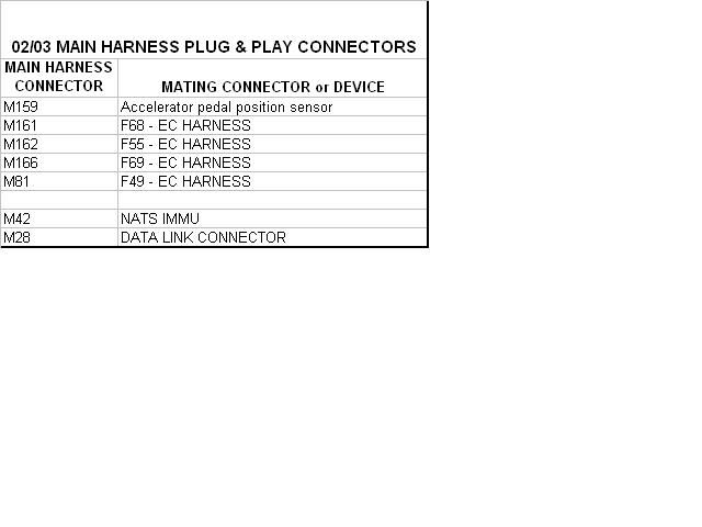
My adapter harness (pruned A33B main dash harness) has 11 connectors.
- 7 of them are plug and play as given in the list below
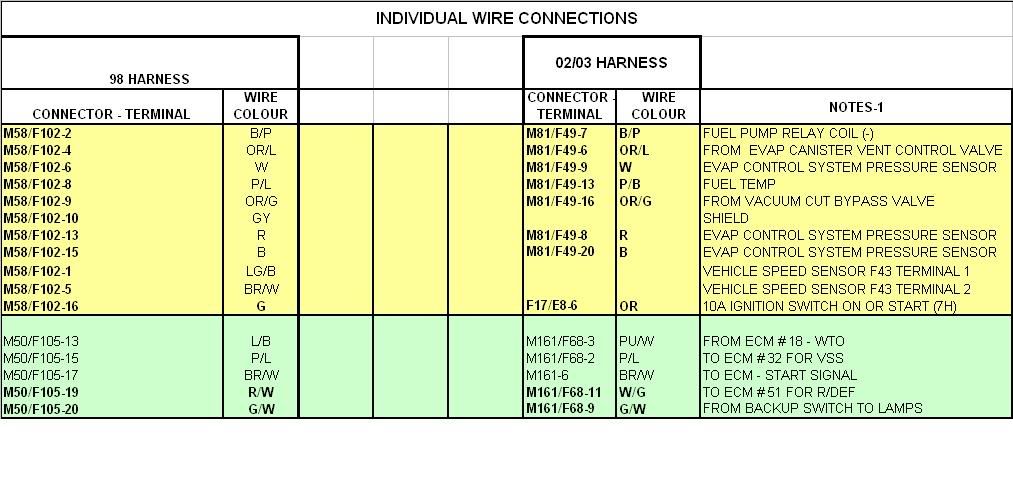
- 2 are ones I cut off my 98 engine harness (F102 & F105) and wired into the adapter harness to make the connections into the 98 main harness (M58 & M50)
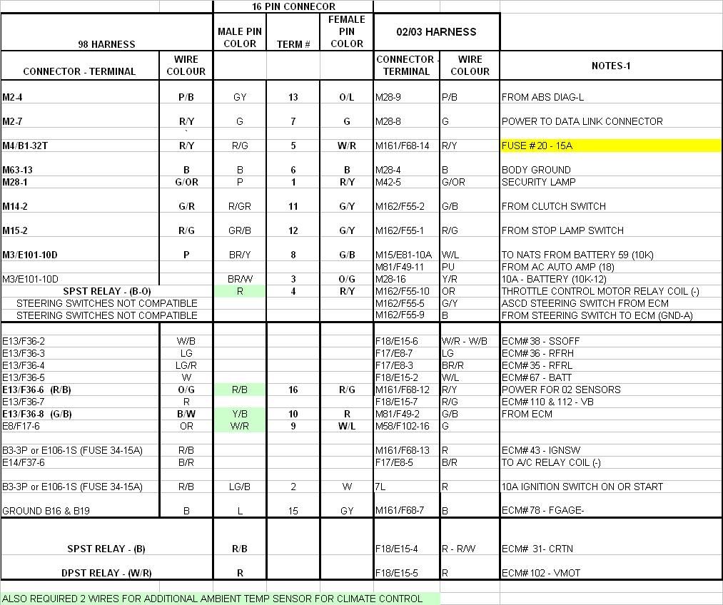
- 2 are ones I used for the remaining loose wire connections I had to make to various devices under the dash
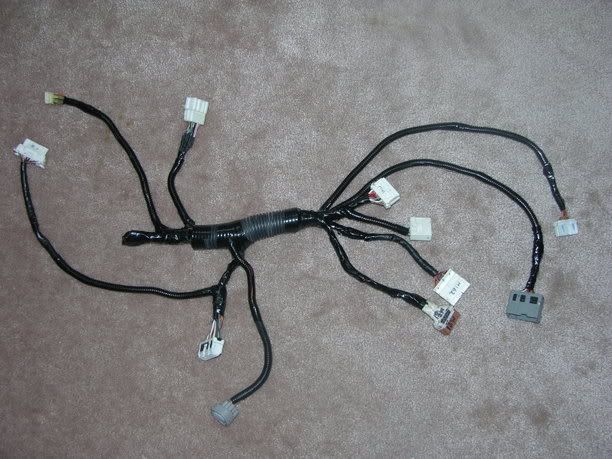
The three spreadsheet snapshots below summarize the majority of the connections
I should note that in addition to the electrical work to get this swap to work, the A33B crank timing ring has to be adapted to the A32 flywheel if you are planning to keep the 5MT transmission.
-EDIT-
certain other systems such as the auto a/c and cruise control required a little bit of improvisation in order for them to retain proper function.
06/08/19 - added VSS connection
My adapter harness (pruned A33B main dash harness) has 11 connectors.
- 7 of them are plug and play as given in the list below
- 2 are ones I cut off my 98 engine harness (F102 & F105) and wired into the adapter harness to make the connections into the 98 main harness (M58 & M50)
- 2 are ones I used for the remaining loose wire connections I had to make to various devices under the dash
The three spreadsheet snapshots below summarize the majority of the connections
I should note that in addition to the electrical work to get this swap to work, the A33B crank timing ring has to be adapted to the A32 flywheel if you are planning to keep the 5MT transmission.
-EDIT-
certain other systems such as the auto a/c and cruise control required a little bit of improvisation in order for them to retain proper function.
06/08/19 - added VSS connection
For the record, did you have auto or manual climate control. Just by looking at the FSM, it doesn't look like it would change many things, but I am just curious. Unfortunately your images aren't coming through, but the fact that you only listed 3 main changes keeps me convinced this can be done without as much rewiring as thought on this forum.
Quote:
AutoOriginally Posted by scrhale
For the record, did you have auto or manual climate control.
Quote:
Is anyone else having a problem viewing them?Originally Posted by scrhale
Unfortunately your images aren't coming through
Quote:
It is what it is. Everyone's perception of what constitutes "alot of wiring" is different. Why waste time trying to convince other people? Just go ahead and do it.Originally Posted by scrhale
but the fact that you only listed 3 main changes keeps me convinced this can be done without as much rewiring as thought on this forum.
Clearly if you can get your hands on a wrecked 02-03, it would make life beyond easier. Having the complete E-Gas harness seems like it simplifies life. Judging from what you have in the spreadsheets, it seems like you kept the A32 BCU. Restating the obvious, the A33B's cruise control is obviously integrated into E-Gas so the A32 BCU cruise control doesn't work. I guess the question is do you still have cruise control and do you have any CEL/SES for not having the CAN lines installed.
Quote:
You would have to get the car for next to nothing to make it feasible from a financial perspective. Although you could part it out to recoup some of your money.Originally Posted by scrhale
Clearly if you can get your hands on a wrecked 02-03, it would make life beyond easier.
Quote:
Without the main dash harness, you would have to hardwire everything.Originally Posted by scrhale
Having the complete E-Gas harness seems like it simplifies life..
Quote:
Yes - I added a resistor network into the 98 steering wheel mounted cruise control to make it compatible with the 02/03 ecu controlled system Originally Posted by scrhale
I guess the question is do you still have cruise control .
Quote:
There is no CAN system for an 02/03 with 6MT.Originally Posted by scrhale
and do you have any CEL/SES for not having the CAN lines installed.
eng92 what are you doing for the VSS? I know the 2000 and up using the ABS signal as the speed signal.
Quote:
I wired it the same way as an 01 would be without traction control. They use a tranny-based speed sensor just like the 4th gen.Originally Posted by nismology
eng92 what are you doing for the VSS? I know the 2000 and up using the ABS signal as the speed signal.
One wire to the cluster and the other one is connected to the sensor ground on the ecu.
Ok so I redid this little map using the 1998 and 2002 FSMs
The lines are written in this format: [A33B ECU Pin #] - [Description] - swap pin [Compatible Pin # from A32]
There are a few comments written on the end of some lines. Please note that you can just bypass the entire "Compatible Swaps" section and re-run all of those components and/or use A33B parts. It is strictly to help minimize the amount of re-wiring you have to do. In addition to that, eng92 already specified that there are 7 harnesses that are plug-and-play so why bother re-running or hardwiring them.
Use common sense to guide you as to whether or not to use A33B parts. Example, Why would you even contemplate trying to use A33B/rerunning O2 sensors, re-running ECM grounds, A/C relays, and Fan Relays? On the other hand, why would you try to use A32 start/ignition equipment even if it is 100% compatible since the immobilizer plays a part.
Note that the term "[Perfect Swap]" used in the 2nd sections denotes an ELECTRICAL condition in which BOTH A32 and A33B use the exact same voltages in the exact same situations. Chances are that the sensors are physically the same, but that will need to be verified.
1998 A32 ECU to 2002 A33B ECU
A33B Parts/Wires/Runs
1, 2, 3, 11, 12, 13 � Injector No. 1, 2, 3, 4, 5, 6 respectively
5, 6, 7, 15, 16, 17 � Injector Signal No. 1, 2, 3, 4, 5, 6, respectively
8 � VTC valve (bank 2)
9 � VTC valve (bank 1)
10 � EVAP canister purge volume control solenoid valve
18 � Engine Coolant temperature sensor signal output (Probably goes to gauge cluster)
26 � Throttle Control Motor Relay � E-Gas harnesses
27 � VIAS Control Solenoid Valve
34 � Tachometer � Run to gauge cluster
60 � EVAP control system pressure sensor
62 � MAF Sensor- can swap pin 54 � voltages are too far off and is not advised to use A32 MAF
64 � Accelerator Pedal Position Sensor 2 Power Supply � E-Gas Harnesses
65 � CPS (PHASE) (Bank 1)
70 � APP Sensor 2 ground � E-Gas Harnesses
71 � Knock Sensor � swap pin 64 � voltages differ slightly from A32 � you shouldn�t try to use an A32 sensor
72 � APP Sensor signal output
73 � APP Sensor 1 � E-Gas Harnesses
74 � APP Sensor 2 � E-Gas Harnesses
83 � TPS 1 � E-Gas Harnesses
84 � TPS 2 � E-Gas Harnesses
85 � CPS (PHASE) (bank 2)
89 � Power Steering Pressure Sensor � can swap pin 39 � voltages are way off. Not sure if you can use A32 Power Steering. It may be possible to swap sensors.
95 � Crankshaft Position Sensor (POS)
101 � Throttle control motor (open) � E-Gas Harnesses
102 � Throttle control motor relay � E-Gas Harnesses
103 � Throttle control motor (close) � E-Gas Harnesses
105 � EVAP canister vent control valve
107 � Throttle Control motor ground � E-Gas Harnesses
115 � Data link connector � Re-run the Consult connector � wires do not line up period
Compatible Parts/Swaps/Pins
21 � Air Conditioner relay � swap pin 12 [Perfect swap]
23 � Fuel Pump Relay � swap pin 11 [Perfect swap]
28 � Vacuum Cut Valve bypass Valve � swap pin 120 [Perfect swap]
35 � Cooling fan relay (Low) � swap pin 14 [Perfect swap]
36 � Cooling fan relay (High) � swap pin 13 [Perfect swap]
38 � ECM relay (self shut-off) � swap pin 4 [Off by .5v � should work anyway]
41 � Heated oxygen sensor 2 heater (bank 1) � swap pin 119 [Perfect swap]
42 � Start Signal � swap pin 20 [Off by 2v � probably needs to be run through immobilizer]
43 � Ignition Switch - swap pin 24 [Perfect swap � probably needs to be run through immobilizer]
44 � PNP Switch � swap pin 22 � May or may not work.
A32 � 5v in gear
A33B � Battery Voltage in gear
45 � Air Conditioner Switch Signal � swap pin 21 [Perfect swap]
47 � Heated Oxygen Sensor 2 heater (bank 2) � swap pin 121 [Perfect swap]
48 � ECM Ground � swap pin 10
51 � Electrical load signal � swap pin 79 [Near perfect. The A33B ECU likes to know when the hi-beams are in use. The A32 ECU does not. You may need to splice in a wire from the high-beam controller on the light switches]
57 � ECM Ground � swap pin 19
58 � Sensors� ground � swap pin 43 [Near perfect. The FSM does not specify which sensors are grounded here]
66 � MAF (Intake Temp Sensor) � swap pin 58 [Perfect swap]
67 � Power Supply for ECM (Back-up) � swap pin 80 [Perfect swap]
75 � Fuel Tank Temperature Sensor � swap pin 52 [Perfect swap]
80 � MAF Sensor ground � swap pin 55 [Perfect swap]
88 � Heated Oxygen Sensor 2 (bank 1) � swap pin 50 [Perfect swap]
90 � Heated Oxygen Sensor 2 (bank 2) � swap pin 51 [Perfect swap]
93 � Engine Coolant Temperature Sensor � swap pin 59 � sensors electrically are identical but why bother using A32 sensor. Just save the rewiring time
106, 108 � ECM grounds � swap pins 25, 108 respectively
110, 112 � Power Supply for ECM � swap pins 67, 72 respectively [Perfect swap]
111 � Sensors� power supply � swap pin 42 [Perfect swap]
Cruise Control Swaps
24 � ASCD CRUISE lamp � runs to gauge cluster � intercept wire from A32 BCU
25 � ASCD SET lamp � see A33B pin 24
50 � ASCD Steering Switch � intercept from BCU � comes from steering wheel � different voltages send different signals
55 � Stop Lamp switch � shuts off Cruise lamp in dash when brake is hit
59 � ASCD Brake switch � shuts off cruise when gear changes, brake is used, clutch is used
Incompatible Parts
4 � Electronic Controlled engine mount (1) [Unused in M/T]
14 � Electronic Controlled engine mount (2) � [Unused in M/T]
30 � A/C Cut Signal
31 � Counter Current Return
33 � MIL
39 � Heated Oxygen sensor 1 heater (bank 1)
40 � Heated Oxygen sensor 1 heater (bank 2)
81 � Refrigerant pressure sensor
109 � CAN Communication Line [Unused in M/T]
113 � CAN Communication Line [Unused in M/T]
Unknown
68 � VSS � voltages and conditions differ.
69 � Fuel Level sensor � may need to intercept from tank, BCU, or A32 cluster
78 � Fuel Level sensor ground
If anyone can just key in on ideas for the Cruise, Incompatible parts, and/or Unknown parts it would be nice. Thanks.
Note I am not liable if anyone starts cutting up their car and (*$#@ something up using my mini-guide here.
On a side note, can anyone tell me what are Electronic Controlled Engine Mounts are? Why do mounts need sensors or controllers?
EDIT: Oh I think twice in the post above you will see situations like:
4 – Electronic Controlled engine mount (1) – Swap pin 33
A32 – 0-.4v at idle
A33B – 0-1v at idle
The second line: "A32 - _____" Denotes how the A32 ECU interprets the signal. The 3rd line denotes how the A33B ECU interprets the signal.
The first number is the A33B Pin number. The swap pin number is the pin from the A32 ECU. I will edit the post to show that.
Why are you talking about "pin swapping" at all?
You have to use the A33B engine harness which has the ecu connector on it. There is no "swapping" of ecu pin terminals to be done.
You have to use the A33B engine harness which has the ecu connector on it. There is no "swapping" of ecu pin terminals to be done.
Quote:
Only used on automatics. They decrease the stiffness at idle to reduce vibration.Originally Posted by scrhale
On a side note, can anyone tell me what are Electronic Controlled Engine Mounts are? Why do mounts need sensors or controllers?
Quote:
You do use the A32 ignition switch and starting system. They do not run through the immobilizer.Originally Posted by scrhale
Use common sense to guide you as to whether or not to use A33B parts. ... On the other hand, why would you try to use A32 start/ignition equipment even if it is 100% compatible since the immobilizer plays a part.
The immobilizer is a single harness connection with one wire going to the ecu and a few others connections for power, ground and the security lamp.
I thought the key sends a signal to the immobilizer which then permits the car to start. I guess I was wrong. I need to look in the FSM again to see how it is wired.
Not only does this provide a VERY vague diagram for those too lazy to go into the FSM and find it themselves, but it also proves that this swap can be accomplished WITHOUT BCU swapping. That is why I was always confused as to why JClaw had problems with his door locks and windows.
To be honest, I have 0 experience in car electronics minus the one head unit swap I did from my 95 to my 98 which is just baby's stuff. I couldn't tell you what a main harness looks like sadly.
Quote:
Why are you talking about "pin swapping" at all?
You have to use the A33B engine harness which has the ecu connector on it. There is no "swapping" of ecu pin terminals to be done.
I am not talking about swapping the physical pin terminals. It is the physical wire that goes into that pin that can be swapped. You will have to cut or splice these wires from the A32 harness. You can use this guide to pick up the A32 main harness, cut the wires you need and pull the rest out. As I stated, you can just simply re-run all of those wires, but this is probably quicker.Why are you talking about "pin swapping" at all?
You have to use the A33B engine harness which has the ecu connector on it. There is no "swapping" of ecu pin terminals to be done.
Not only does this provide a VERY vague diagram for those too lazy to go into the FSM and find it themselves, but it also proves that this swap can be accomplished WITHOUT BCU swapping. That is why I was always confused as to why JClaw had problems with his door locks and windows.
To be honest, I have 0 experience in car electronics minus the one head unit swap I did from my 95 to my 98 which is just baby's stuff. I couldn't tell you what a main harness looks like sadly.
Quote:
You have to use the A33B engine harness which has the ecu connector on it. There is no "swapping" of ecu pin terminals to be done.
That is what i was thinking. Originally Posted by eng92
Why are you talking about "pin swapping" at all?You have to use the A33B engine harness which has the ecu connector on it. There is no "swapping" of ecu pin terminals to be done.
Back on topic:
What should be done with the extra A/C wiring and Exhaust manifold O2 sensors?
For the A/C, I guess there are 3 options:
1.) Leave A32 A/C and connect existing sensors
2.) Leave A32 A/C and retrofit/swap in A33B sensors
3.) Use A33B A/C.
Do MIL and Counter Current Return run to the Gauge Cluster?
What should be done with the extra A/C wiring and Exhaust manifold O2 sensors?
For the A/C, I guess there are 3 options:
1.) Leave A32 A/C and connect existing sensors
2.) Leave A32 A/C and retrofit/swap in A33B sensors
3.) Use A33B A/C.
Do MIL and Counter Current Return run to the Gauge Cluster?
Quote:
The immobilizer and ignition system are two seperate things. The only relationship the two have is proximity since the immobilizer is screwed to the key cylinder in the A33B. But since the A32 key cylinder and ignition switch is going to be retained, what i'll be doing is taping the key to the immobilizer and wiring it up close to the ECU for simplicity. The connection it requires is 12V constant, 12V switched, Ground, LED output for security light, and feedback to the ECU. The A32 starting system will be unchanged.Originally Posted by scrhale
I thought the key sends a signal to the immobilizer which then permits the car to start. I guess I was wrong. I need to look in the FSM again to see how it is wired.
This is kinda of an off idea, but if the situation were ever occur where you couldn't find an immobilizer, couldn't you just get an immobilizer from another car and install a by-passer?
EDIT: I just found the NVIS crap in the FSM. HA ... I never thought the immobilizer was just one stupid wire. Was the reason that we need 2 ignition systems because the A33B ignition switch didn't fit in the steering column right?
EDIT: I just found the NVIS crap in the FSM. HA ... I never thought the immobilizer was just one stupid wire. Was the reason that we need 2 ignition systems because the A33B ignition switch didn't fit in the steering column right?
eng92 can you fill me in as to what modifications to the A32 engine room harness were required and what other relays are needed other then one for the throttle motor and 1 for the ECU? Thanks.
Quote:
Currently those are the only two additional relays I have added. The existing single pole ECCS relay was replaced with a 2-pole one I got from a wrecking yard. The now spare single pole relay was used for the throttle motor. It fit nicely into the empty space in the relay box.Originally Posted by nismology
eng92 can you fill me in as to what modifications to the A32 engine room harness were required and what other relays are needed other then one for the throttle motor and 1 for the ECU? Thanks.
For the underhood wiring, I cut the F17 and F18 connectors off the end of the A33B engine harness. Most of these wires were re-attached to the F36 connector that I cut off from the old A32 engine harness. More detail on the specific terminal connections for these is given in the spreadsheet above.
I have a hardcopy of the above spreadsheet, marked up with a few additional connections, floating around in my garage somewhere. I will try and find it.
Quote:
For the underhood wiring, I cut the F17 and F18 connectors off the end of the A33B engine harness. Most of these wires were re-attached to the F36 connector that I cut off from the old A32 engine harness. More detail on the specific terminal connections for these is given in the spreadsheet above.
I have a hardcopy of the above spreadsheet, marked up with a few additional connections, floating around in my garage somewhere. I will try and find it.
Awesome info. It's starting to make more and more sense to me. Originally Posted by eng92
Currently those are the only two additional relays I have added. The existing single pole ECCS relay was replaced with a 2-pole one I got from a wrecking yard. The now spare single pole relay was used for the throttle motor. It fit nicely into the empty space in the relay box.For the underhood wiring, I cut the F17 and F18 connectors off the end of the A33B engine harness. Most of these wires were re-attached to the F36 connector that I cut off from the old A32 engine harness. More detail on the specific terminal connections for these is given in the spreadsheet above.
I have a hardcopy of the above spreadsheet, marked up with a few additional connections, floating around in my garage somewhere. I will try and find it.
Quote:
One wire to the cluster and the other one is connected to the sensor ground on the ecu.
How are you inputting the VSS signal to the ECU?Originally Posted by eng92
I wired it the same way as an 01 would be without traction control. They use a tranny-based speed sensor just like the 4th gen.One wire to the cluster and the other one is connected to the sensor ground on the ecu.
Quote:
The ecu gets the VSS signal from the gauge cluster.Originally Posted by nismology
How are you inputting the VSS signal to the ECU?
Quote:
I'm trying to avoid having to swap in the A33B gauge cluster so is there any way i can wire the VSS directly to the ECU or does the gauge cluster modify the signal to the ECU?Originally Posted by eng92
The ecu gets the VSS signal from the gauge cluster.
Quote:
The FSMs show different voltage inputs to the ecu. Originally Posted by nismology
I'm trying to avoid having to swap in the A33B gauge cluster so is there any way i can wire the VSS directly to the ECU or does the gauge cluster modify the signal to the ECU?
A32 - 5.2V ave
A33B - 2.5V ave
I had the A33B cluster installed for about 8 months before I carried out my swap. The wierd thing I came across after I installed it was there was a "soft" speed limiter at about 120 km/hr. I could "break" through if I was accelerating rapidly in say 4th gear but if I was in fifth at about 110 and floored it it would not go over 120. My OBD scanner gave me a vehicle speed that was exactly 4X what my speedometer was showing.
Long story short is that the cluster does modify the VSS signal.
If you do not use the A33B cluster, you will need to add in the A32 coolant temp sensor so your cluster gauge will function.
Quote:
A32 - 5.2V ave
A33B - 2.5V ave
I had the A33B cluster installed for about 8 months before I carried out my swap. The wierd thing I came across after I installed it was there was a "soft" speed limiter at about 120 km/hr. I could "break" through if I was accelerating rapidly in say 4th gear but if I was in fifth at about 110 and floored it it would not go over 120. My OBD scanner gave me a vehicle speed that was exactly 4X what my speedometer was showing.
Long story short is that the cluster does modify the VSS signal.
If you do not use the A33B cluster, you will need to add in the A32 coolant temp sensor so your cluster gauge will function.
Thanks for the response. I was just wondering if the 2k2 ECU would be satisfied getting a direct signal or if i'd experience your "soft" speed limiter at like 40 MPH or something. lol I hope it works. Originally Posted by eng92
The FSMs show different voltage inputs to the ecu. A32 - 5.2V ave
A33B - 2.5V ave
I had the A33B cluster installed for about 8 months before I carried out my swap. The wierd thing I came across after I installed it was there was a "soft" speed limiter at about 120 km/hr. I could "break" through if I was accelerating rapidly in say 4th gear but if I was in fifth at about 110 and floored it it would not go over 120. My OBD scanner gave me a vehicle speed that was exactly 4X what my speedometer was showing.
Long story short is that the cluster does modify the VSS signal.
If you do not use the A33B cluster, you will need to add in the A32 coolant temp sensor so your cluster gauge will function.

And as for the coolant temp sending unit, the plan is to use the 3.0 coolant tube.
I'm having some trouble understanding the 3rd spreadsheet and the some of the notes. Did you wire each of those things up seperately?
And as for the 2 connectors on the adapter harness that you used to wire up various things under the dash, which part of the spreadsheet contains the info concerning them?
And as for the 2 connectors on the adapter harness that you used to wire up various things under the dash, which part of the spreadsheet contains the info concerning them?
Quote:
And as for the 2 connectors on the adapter harness that you used to wire up various things under the dash, which part of the spreadsheet contains the info concerning them?
In the third spreadsheet, the three central columns for "16 pin connector" represent one of the 2 additonal connectors that I used. The mating part of that connector was hardwired into the positions under the dash designated in the first 2 columns. Originally Posted by nismology
I'm having some trouble understanding the 3rd spreadsheet and the some of the notes. Did you wire each of those things up seperately?And as for the 2 connectors on the adapter harness that you used to wire up various things under the dash, which part of the spreadsheet contains the info concerning them?
There are two more columns of notes in that spreadsheet that I left off because it would have made the text too small to read due to the width of the image. PM me your email address and I can send it to you.
Quote:
You will need to add an extra wire for the second coolant sensor as the A33B only has a single sensor for all functions.Originally Posted by nismology
And as for the coolant temp sending unit, the plan is to use the 3.0 coolant tube.
I will probably do the same this winter. The coolant temp output (WTO) from the ecu is not compatible with the A/C amp. The only problem it creates is instead of waiting for the coolant temperature to get to a certain value before turning the blower fan on in AUTO mode for heat, the fan comes on right away. Only really a minor inconvenience in the winter.
Quote:
I will probably do the same this winter. The coolant temp output (WTO) from the ecu is not compatible with the A/C amp. The only problem it creates is instead of waiting for the coolant temperature to get to a certain value before turning the blower fan on in AUTO mode for heat, the fan comes on right away. Only really a minor inconvenience in the winter.
I'll just cannibalize the wire from the A32 EC harness and run it directly to the gauge cluster.Originally Posted by eng92
You will need to add an extra wire for the second coolant sensor as the A33B only has a single sensor for all functions.I will probably do the same this winter. The coolant temp output (WTO) from the ecu is not compatible with the A/C amp. The only problem it creates is instead of waiting for the coolant temperature to get to a certain value before turning the blower fan on in AUTO mode for heat, the fan comes on right away. Only really a minor inconvenience in the winter.
Another thing i was confused about.....the A32 guage cluster recieves the VSS signal at terminals 2 and 4 from VSS terminals 1 and 2. The A32 ECU recieves the VSS signal directly to pin 29. My question is this...how can the signal get to three difference places if there are only 2 terminals on the VSS? I need to know so i can figure out how to get the signal to all three places. Thanks in advance.