

? about shift-fast mod


Originally Posted by Cdg2125
Awesome. That four gang maintained contact switches should do the trick. I do want the maintained conatact right? The other switch is momentary non-maintained. I'm guessing that's not what I want. I contacted Digikey as well to see if they had anything good.
Using this will make you manually down shift correct?
Using this will make you manually down shift correct?
You then wire from the normally-open contact to Solenoid A and Solenoid B differently for each switch ( 3rd gear actually requires no connections) so the 1st gear button energizes both solenoids, then match the logic chart I posted back a ways to pick the solenoids for each gear.
Once pulled into 1st gear and switched to Race mode, pushing any button will put you into that gear (at any speed - be careful) going up or down from 1st to 4th or back the other way. Congratulations - you just re-invented the Ford Edsel pushbutton shifter first seen in 1958.

Originally Posted by Tatanko
My shift_fast is up and working. No on/off switch, but it works for now (it's unplugged atm). I may just go with that 4-gang switch as well, it seems like a good idea.
I'm still impressed that you guys keep thinking and trying stuff and don't give up easily...

You could call the 4-button version the Shift_Four_Fast or something cheesy like that. This would actually work rather well, I think. Positive gear selection both up and down - something lots of people seem to want. Go into business and make some for others. That should add to your education, and make you never do that again!


Ok I'm glad to hear this idea will work. I spent so long looking at sites and searching all over the web trying to find a switch group like that. My thought now is how to draw the power to the box. I was thinking of using a relay from the power wire that runs to the solenoids. Is it one wire or two? I would have my switch control that wire and instead of sending power to the solenoids, send it directly up to the box to be controlled. When I look at the FSM it looks like that one relay would work but Im unsure if I'm reading it correctly. I already have a schematic drawn up so maybe I'll post that sometime soon to see what you guys think.
Originally Posted by Cdg2125
Ok I'm glad to hear this idea will work. I spent so long looking at sites and searching all over the web trying to find a switch group like that. My thought now is how to draw the power to the box. I was thinking of using a relay from the power wire that runs to the solenoids. Is it one wire or two? I would have my switch control that wire and instead of sending power to the solenoids, send it directly up to the box to be controlled. When I look at the FSM it looks like that one relay would work but Im unsure if I'm reading it correctly. I already have a schematic drawn up so maybe I'll post that sometime soon to see what you guys think.
When the DPDT switch is set to NORMAL, the computer controls the tranny as usual. When you switch to RACE, then the switch bank controls what comes out and goes to the two tranny solenoids. Just switches and wires.
My Shift_Fast MSD controller takes the two wires from the tranny computer that can be found in the engine wiring harness, goes into the cabin and controls the output with electronics and relays for automatic sequential shifting, and feeds the output two wires back to the tranny - through a DPDT switch for NORMAL and RACE - same thing we're talking about.
You could do this with one DPDT toggle and the four-position switch bank and some wiring. And you could have the first up-down-button 4-gear Maxima shifter. It's actually quite do-able if you can get the right switch bank...

Yeah I was looking at Pats site and noticed that I was wrong about that relay. The DPDT switch will change the flow of power to the switch bank. Let me get this straight tho...
I'm just confused on the wires from the tranny. I was thinking to have wires spliced to the existing power wires for the solenoids, and when the DPDT switch was switched to Race then the power flow would then be switched into the switch bank. Each button for the shift bank would then go to the designated solenoid wires. When switched back to Normal the power would run regularly again. Is that right or am I missing a step? As I said, I have a schematic drawn up so I'll try to post it soon to see if I'm on the right track.
I'm just confused on the wires from the tranny. I was thinking to have wires spliced to the existing power wires for the solenoids, and when the DPDT switch was switched to Race then the power flow would then be switched into the switch bank. Each button for the shift bank would then go to the designated solenoid wires. When switched back to Normal the power would run regularly again. Is that right or am I missing a step? As I said, I have a schematic drawn up so I'll try to post it soon to see if I'm on the right track.
Originally Posted by Cdg2125
Yeah I was looking at Pats site and noticed that I was wrong about that relay. The DPDT switch will change the flow of power to the switch bank. Let me get this straight tho...
I'm just confused on the wires from the tranny. I was thinking to have wires spliced to the existing power wires for the solenoids, and when the DPDT switch was switched to Race then the power flow would then be switched into the switch bank. Each button for the shift bank would then go to the designated solenoid wires. When switched back to Normal the power would run regularly again. Is that right or am I missing a step? As I said, I have a schematic drawn up so I'll try to post it soon to see if I'm on the right track.
I'm just confused on the wires from the tranny. I was thinking to have wires spliced to the existing power wires for the solenoids, and when the DPDT switch was switched to Race then the power flow would then be switched into the switch bank. Each button for the shift bank would then go to the designated solenoid wires. When switched back to Normal the power would run regularly again. Is that right or am I missing a step? As I said, I have a schematic drawn up so I'll try to post it soon to see if I'm on the right track.
The output from the transmission computer goes to both the NORMAL/RACE switch and the input to the switch bank. The DPDT switch decides which pair of wires actually go to the transmission.
Hope this helps.....
Well I think I confused myself. I'm still looking at Pat's site and looking at your post. I see that wires from the N/R switch attach to the 1/2/3 switch but I dont know how that would work with the switch bank. Are the wires cut and rerouted to the switch? Or would I be tapping into the exsisiting wires?
Reading your post before confused me. "Original wires from the tranny to the switch... Connecting wires from the switch bank to those wires...." It just all seemed to not make sense to me. Maybe because I have a certain picture in my head about the wires.
I know how to get the power to the solenoids from the switch box. I can understand the idea of switching power from the N/R switch but I just can't make it click in my head how the wires work. I can't see how bringing the original TCU wires to the N/R switch works. On Race I understand that the power will be moved into the switch bank, but on Normal, how is the TCU able to switch everything? That makes me think the original TCU wires need to be tapped...I can't see by that.
My thought is that the original wires from the TCU to the solenoids would be cut and go up to the Normal and the Race prongs. The Normal wires would then come off one of the output prongs and go back to the solenoids. The other output prong would go to the switch bank and then each button would go to the designated solenoid. I dont see how the TCU can control the solenoid power once it is routed to the switch because the 12v output only comes from one prong. This would give each solenoid power at the same time and not allow the TCU to control that power. What am I doing wrong here?
Originally Posted by Cdg2125
Ok thanks Pat. I'm still not sure of the wiring up to the switch tho. That's all that is confusing me.
I just need to figure out power to the N/R switch. It's not making sense to me. I understand how to run the power from everything else. I just cant figure it out how the TCU will be able to control the Normal mod.
Originally Posted by Cdg2125
I just need to figure out power to the N/R switch. It's not making sense to me. I understand how to run the power from everything else. I just cant figure it out how the TCU will be able to control the Normal mod.
The two wires from the transmission computer go to one side of the DPDT "N/R" switch and go through the common poles of the DPDT switch to the transmission.
The proposed switch bank also connect to the same two wires leaving the computer and goes through the switch bank to the other side of the "N/R" DPDT switch.
The transmission does as it is told by either the tranny computer directly - stock form - or whatever the switch bank does with the tranny computer wires' voltages.

Originally Posted by grey99max
Hint:
The two wires from the transmission computer go to one side of the DPDT "N/R" switch and go through the common poles of the DPDT switch to the transmission.
The proposed switch bank also connect to the same two wires leaving the computer and goes through the switch bank to the other side of the "N/R" DPDT switch.
The transmission does as it is told by either the tranny computer directly - stock form - or whatever the switch bank does with the tranny computer wires' voltages.
When switched to Race, does the switch pull power through the tapped wires from the original wires into the bank? Is that where the power is coming from?
Originally Posted by Cdg2125
I dont see how that controls the power. There isnt an in and out on the switch bank. Two wires from the TCU (a) need to go to the Normal side of the switch. If I tap those same wires (a) and bring the other wires (b) to the switch bank, the power from the bank and the switches go directly to the designated solenoids. There is no other output do go back to the Race part of the switch. Which prongs on the DPDT switch are the common poles?
When switched to Race, does the switch pull power through the tapped wires from the original wires into the bank? Is that where the power is coming from?
When switched to Race, does the switch pull power through the tapped wires from the original wires into the bank? Is that where the power is coming from?
The "common" pole of the DPDT switch is the center contact - the one that goes from the "NORMAL" position and wire leading to the tranny computer output, or the "RACE" position contact that is fed from the switch bank. The "common" contacts go to the transmission solenoids as two wires - the same wires that originally left the computer.
Notice I'm not drawing any diagrams for you..... streetz, step up and help out here - I bet you've got it figured.

So is there only one wire for the TCU output? Is it just one wire for power or what? It still doesnt make sense. Why do you need to have two wires out of the bank?
The two wires (Lt G/Blk, Red/Yel) come out of the TCU and run to the solenoids. I use those wires and splice a wire into each one. Those new wires are run to B (diag). They are also run to E. So A and D will go back to the original two TCU wires, and C and F go to the switch bank. From the switch bank each button would have 2 wires for 1st, 1 for 2nd, 0 for 3rd, 1 for 4th. Is that right yet or no?!

Ignore the actual figure I just wanted to use the letters
Another idea....using that same picture....
Lt G/Blck wire from TCU has wire spliced into it. That new wire goes to B. A and C will be the out puts. A will go to the switch bank, and C will go back to be spliced to the original TCU wire. The Red/Yel wire will also be spliced and that new wire goes to E. D will be that output to the bank and F will go back to be spliced to the original TCU wire.
That is the only other thing I can think of.
The two wires (Lt G/Blk, Red/Yel) come out of the TCU and run to the solenoids. I use those wires and splice a wire into each one. Those new wires are run to B (diag). They are also run to E. So A and D will go back to the original two TCU wires, and C and F go to the switch bank. From the switch bank each button would have 2 wires for 1st, 1 for 2nd, 0 for 3rd, 1 for 4th. Is that right yet or no?!
Ignore the actual figure I just wanted to use the letters
Another idea....using that same picture....
Lt G/Blck wire from TCU has wire spliced into it. That new wire goes to B. A and C will be the out puts. A will go to the switch bank, and C will go back to be spliced to the original TCU wire. The Red/Yel wire will also be spliced and that new wire goes to E. D will be that output to the bank and F will go back to be spliced to the original TCU wire.
That is the only other thing I can think of.
Originally Posted by Cdg2125
Another idea....using that same picture....
Lt G/Blck wire from TCU has wire spliced into it. That new wire goes to B. A and C will be the out puts. A will go to the switch bank, and C will go back to be spliced to the original TCU wire. The Red/Yel wire will also be spliced and that new wire goes to E. D will be that output to the bank and F will go back to be spliced to the original TCU wire.
That is the only other thing I can think of.
Then again, that's basically what I did and I never figured out why mine didn't work
On another note, grey, do you suppose you could look over my OLD setup and tell me what was wrong with it possibly? (if there was anything)

Ok, so basically, I had it as follows:
1. I had solenoid "A's" wire (from TCU) hooked to pin B.
2. I had solenoid "B's" wire (from TCU) hooked to pin E.
3. I had an "out" wire (to the tranny) on pins A and D, going to their corresponding wire on the tranny.
4. I had C going to pin H, and pin F going to pin K.
5. Pins I and L had wires going to their respective wires on the tranny (combined with the corresponding wires from pins A and D to form 2 output wires instead of 4).
6. I had pin J going out to it's respective wire on the tranny (combined with respective wires the same as A, D, I, and L).
7. I had nothing hooked to pin G.
What could have possibly been wrong with this?

The switch to connect and disconnect is wired properly, ie power goes from B & E to A & D in normal position. When connecting for the shift-fast mod power goes from B & E to C & F and then to H & K on the second switch, again this is correct.
You need to disconnect one solenoid for 2nd gear and two solenoids for 3rd gear. Therefore the J & G end of the switch is fine for second gear, ie A solenoid disconnected and B solenoid connected.
Now the other end, pins I & L should be connected to NOTHING because A & B solenoids both need to be disconnected for 3rd gear.
Originally Posted by Jime
Now the other end, pins I & L should be connected to NOTHING because A & B solenoids both need to be disconnected for 3rd gear.
Originally Posted by Tatanko
Why aren't I and L connected to anything? Why would I and L be used for 3rd gear if the DPDT switch is center-off? Wouldn't I and L be used for 1st gear if 2nd gear is J and G?
Originally Posted by Jime
You didn't say you had a center off switch. Ok it should work then with it wired that way, just don't mess up when shifting from 2nd to 3rd and miss the center position and go to 1st.
Originally Posted by grey99max
Just wondering if anyone has gotten their mod to work?
Originally Posted by Cdg2125
Well unfortunately I dont have the time to design anything right now so Tatanko is going to get the credit for my 4 gang idea.
Originally Posted by babymac
Please do a write up because I want to do this too.
Well I'm going to have some time this winter, hopefully, to get some stuff done. I'm looking to clean up my interior a bit by relocating some of my current switches, and add a few. I don't just want to throw this thing in there and go, I want it to be "clean" as well.
EDIT: I just ordered that 4-gang switch off the site linked to. The ordering process was a bit odd, and they don't even tell you shipping costs 'til the end. I chose USPS Priority and it ended up being free They require you have a minimum purchase of $10, and the switch is only $9, so I opted to grab an LED indicator. Who knows, maybe I'll find a use for it
EDIT: I just ordered that 4-gang switch off the site linked to. The ordering process was a bit odd, and they don't even tell you shipping costs 'til the end. I chose USPS Priority and it ended up being free
They require you have a minimum purchase of $10, and the switch is only $9, so I opted to grab an LED indicator. Who knows, maybe I'll find a use for it
Originally Posted by Cdg2125
Pat are you wiring it the way I said before? If my idea works then I'll have no problem explaining to my father what I'm doing to my newly rebuilt tranny haha.
 clown....until he "test" drove it
The switch(es) has arrived.

It's pretty neat how they work. Has all kinds of holes you can use to bolt it to stuff (which I plan to do). Operates very smoothly, and feels "solid", not like it's going to break (which I was afraid of).
The thing you see on the right is simply a green LED indicator. I had to order at least $10 of stuff, and that was only $1, so why not? Looks easy to hook up and install compared to doing your own LED work, so I'm sure I'll find a use for it.
It's pretty neat how they work. Has all kinds of holes you can use to bolt it to stuff (which I plan to do). Operates very smoothly, and feels "solid", not like it's going to break (which I was afraid of).
The thing you see on the right is simply a green LED indicator. I had to order at least $10 of stuff, and that was only $1, so why not?
Looks easy to hook up and install compared to doing your own LED work, so I'm sure I'll find a use for it.
I was also thinking to hook up LED's in the dash for that mod. So you can see which gear it's in on the dash. Can't do it with the stock shifter so maybe with this mod haha. Good luck on the wiring. Let me know if the idea works Pat!
Originally Posted by Cdg2125
I was also thinking to hook up LED's in the dash for that mod. So you can see which gear it's in on the dash. Can't do it with the stock shifter so maybe with this mod haha. Good luck on the wiring. Let me know if the idea works Pat!
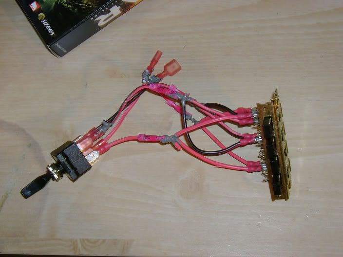
Should look something like this when I'm done:

Ahh it didn't work 
This time I had it wired as follows:
1. B and E were the input from the TCU.
2. C and F went to the 4-gang switch.
3. A and D went to the tranny.
4. H and K got input from C and F (respectively).
5. G and J went to the tranny. (1ST GEAR)
6. I and L were ignored.
7. Q got input from F.
8. P went to the tranny. (2ND GEAR)
9. M, N, O, and R were ignored.
10. S, T, U, V, W, and X were ignored. (3RD GEAR)
11. Z got input from C.
12. Y went to the tranny. (4TH GEAR)
13. A2, B2, C2, and D2 were ignored.
WHY DOESN'T THIS WORK?!?!?! AHHH!!! haha