When you click on links to various merchants on this site and make a purchase, this can result in this site earning a commission. Affiliate programs and affiliations include, but are not limited to, the eBay Partner Network.
Posted awhile back regarding my 5.5 blowing itself up (most likely precats, bluh), and faced with a decision to trade the car in and take a loss, or swap another engine in, I decided to go with the latter. More fun, right?
I'm making this thread to sort of chronicle the process, and hopefully post up any gotchas/issues I ran into that I haven't seen detailed in my travels through the various forums. (not to say they haven't been, but info is scattered.)
Mods, if this isn't the appropriate place for this, apologies, let's get it moved to the right one.
As far as skills, I'm fairly mechanically-inclined. While I don't have access to a lift or anything, I've got lots of air tools, a small compressor, lots more ratchets and sockets, swivels, wrenches, and a bunch of specialty stuff. If I need it, and it will make the job easier, I'll buy it.
I'm a little torn on this, because I purchased a 6th gen engine to swap in (2005 Maxima AT) and I'm going to be doing some work on it before dropping it in there, so this may split up between the 5th and 6th gen forums. I'll make sure the threads all link together if there's multiple.
Let me know if there's any pictures you guys want to see, or questions about this process, and I'll give you whatever I know, but since this is the first time I'm embarking on this, it may or may not be correct. I'll let the veterans chime in on that kinda stuff, but for the most part, this will just be a narrative of me doing this, problems, successes, and everything.
Overview:
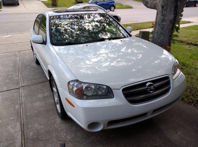
I've got a 2002 Maxima SE, 6MT with HLSD. Totally stock.
Rings appear shot, large clouds of smoke dump from the tailpipe constantly, runs rough. Front bank plugs drenched in oil.
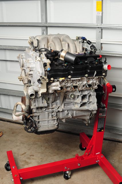
I've purchased a used engine with 55k miles on it out of a 2005 Maxima, AT. I picked it up from a local auto recycler and brought it home.
Upgrades:
No sense in tearing everything apart and putting it all back together stock, when there's other fun things to do, right?
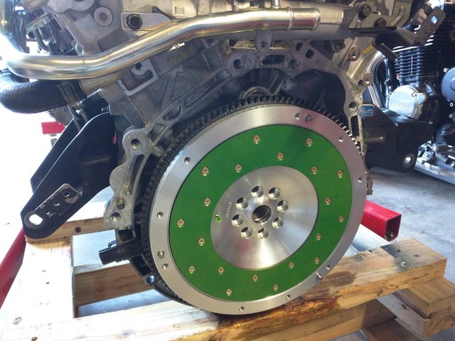
Fidanza lightweight flywheel
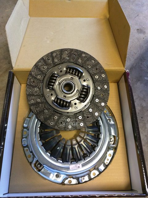
Exedy Stage 1 clutch
OBX Headers
Magnaflow high-flow cat
Energy Suspension engine mounts
Many other components were purchased, but mainly as OEM replacements for wear components.
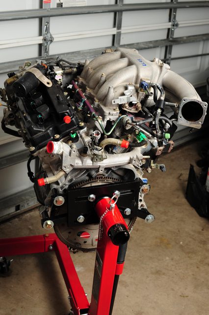
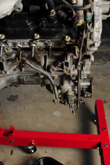
Engine was purchased from LKQ, and shipped in on a crate.
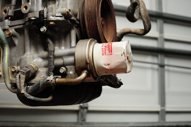
Oil filter was supporting the front of the engine :(
Seems the cooler was still alright though, will be replacing the o-ring and such as part of the teardown work.
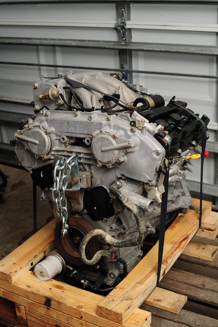
Aside from that and a few chopped hoses or cables, a slightly dented lower oil pan, and a couple other things, it appears to be in pretty good condition. Still has a Nissan filter on it, and inside the valve cover is clean and nice, so had regular oil changes.
I borrowed a hoist from a friend, and bought a cheap engine stand to support it while I do most of the work on the engine, to make things easier. It bolted right up to the block using some 14x80mm bolts, though I could have gone a bit longer, maybe 85mm. The lower bolt I used a non-tapped hole, and ran a 100mm bolt through with washer/nut to give some extra support.
I started by removing the EGR valve assembly, since the 2002 ECU won't be expecting one. Drained some coolant from that area. After setting it up on the stand, I pulled the passenger side engine mount bracket, as the recycler had bent the bolt upon removing the engine from the car, so i'll need to replace that.
Since I have a 6MT, I'll need to swap the upper oil pan over from my current engine onto this one, which was set up for AT. The lower oil pan is dented, but I have the one attached to my current upper oil pan, so I'll just swap that over as well. Oil cooler hardline was also crushed a bit, so i'll either swap or buy new.
I'll flesh this out a bit more when pulling the pan from my other engine, but there's not much to it. I just forgot to take a couple pictures while removing the pan.
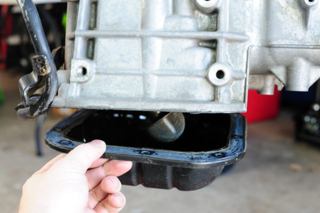
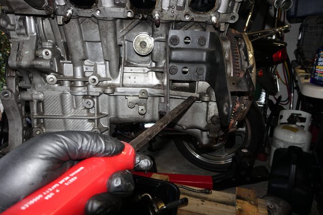
To start, I removed the lower oil pan from the upper pan. This is fairly easy, there are 10 10mm bolts holding it in. Breaking it free from the RTV was a bit difficult, I set a large screwdriver against one corner and tapped at it with a hammer to try and push it down and away. This isn't a good idea if you want to reuse the pan, as it bent the corner of my pan, but I didn't care since it was already dented. Once I got it open enough, I used a large prybar to wedge into the opening and pull the pan downwards.
I'm trying to use the largest tool I can when prying on these areas, as it distributes the force and prevents marring the aluminum.
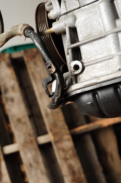
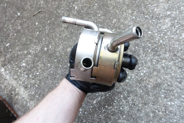
I then needed to finish removing the other components from the upper pan, namely the oil cooler and it's attachments.
I probably didn't really need to disconnect all this stuff from the upper pan since I was removing it anyway, but I did.
I disconnected the lower coupling from the cooler and removed it, with the goal of draining the most coolant I could out of those two lines.
Then I removed the upper rigid coolant line banjo bolt and disconnected the (broken) oil pressure switch from the oil pan. I also disconnected the upper rubber hose from the other side of the cooler's piping, and removed the hard line on that side of the engine as well, so the cooler was completely freed.
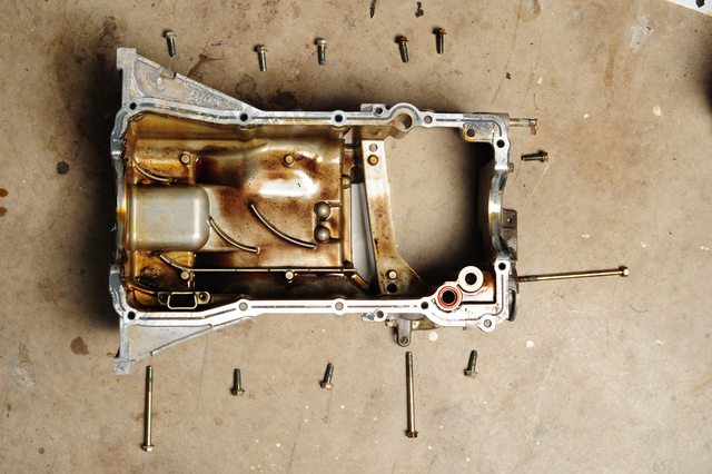
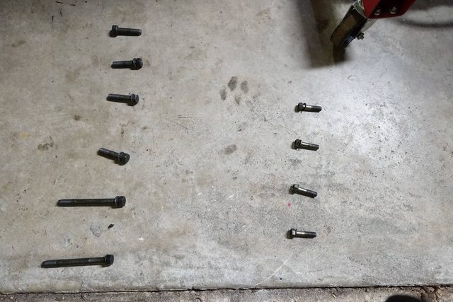
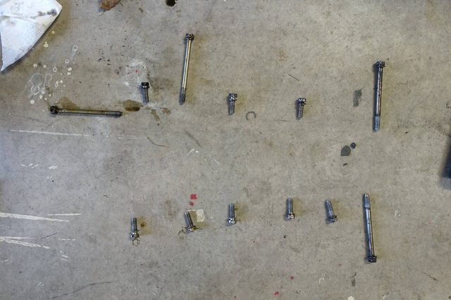
With that out of the way, I removed the 12 bolts holding the upper oil pan in place. These are varying sizes (3 different from what I saw), and I arranged them around the oil pan so that I would remember what went where!
I'm keeping all my fasteners in labelled plastic baggies so I don't mix them up.
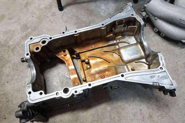
The oil pan was fairly easy to pry off, even without doing the 'special cutter tool' technique, by using a large pry bar in the provided opening (see FSM). This pries outside of the actual mating surfaces, so there's very little chance of damage. I ran a cutter blade around the slot as I was prying to help cut away some of the RTV within, which made things a little easier. I also made sure to pry from alternating sides because there are a couple dowels that I didn't want to bend. The pan popped right off and was also fairly clean. I noted there are two o-rings connecting the oil pump to the filter port that will need to be replaced as well.
Looks good. When you go back together with the oil pan use a good RTV like Hondabond. The upper pan is a lot of work to remove while it's in the car so a pricey RTV is well worth it.
I'm assuming your replacing the rear main seal as well?
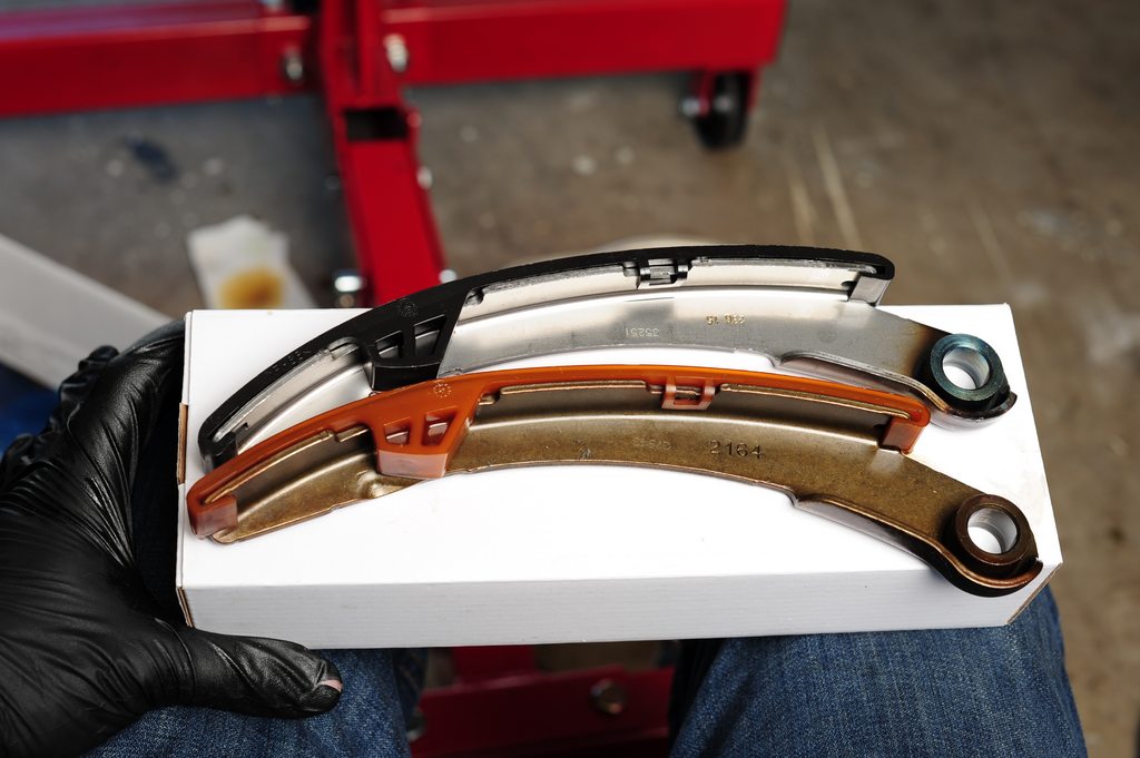
I did the timing chain on this engine while it's out of the car, to address the issue with the slack guide on these engines, and just to freshen up everything inside so it'll be good for another 150k.
A quick little visual of what changed.. The slack guide was superceded by another part which seems to beef up the plastic area near the top, as well as be made from a different plastic:
Looks good. When you go back together with the oil pan use a good RTV like Hondabond. The upper pan is a lot of work to remove while it's in the car so a pricey RTV is well worth it.
I'm assuming your replacing the rear main seal as well?
I'll get some on the way. I might as well replace the rear main since i'm going to be pulling the flex plate off and installing the new flywheel.
I was originally looking at Permatex Ultra Black.. anyone used that and had good results? I've used it before on small things, but not sure if that's the right thing for the job. I can just get the official Nissan stuff too..
I uses permatex ultra black and copper. I douse the crescent seal lol.
Last edited by Child_uv_KoRn; 05-09-2016 at 11:32 PM.
I'll get some on the way. I might as well replace the rear main since i'm going to be pulling the flex plate off and installing the new flywheel.
I was originally looking at Permatex Ultra Black.. anyone used that and had good results? I've used it before on small things, but not sure if that's the right thing for the job. I can just get the official Nissan stuff too..
Definitely do the rear main. You have to pull the upper oil pan to do it.
I haven't used the Permatex but others here have. The Nissan stuff never seems to fail from the factory. If the dealer sells the same stuff it might be good. I do some work for a shop that specializes in high end Euro cars and exotics. Hondabond is the only RTV in our shop and goes on everything from an old Mercedes to a Ferrari to a race prepped Porsche.
It was discussed a little in my original thread, but from what i'd read from SurraTT, it required a bit more than a direct drop-in (timing/fueling). This is meant to be a reliable commuter car, so I wanna keep it close to stock. Maybe next swap!
Originally Posted by Derrick2k2SE
Definitely do the rear main. You have to pull the upper oil pan to do it.
I haven't used the Permatex but others here have. The Nissan stuff never seems to fail from the factory. If the dealer sells the same stuff it might be good. I do some work for a shop that specializes in high end Euro cars and exotics. Hondabond is the only RTV in our shop and goes on everything from an old Mercedes to a Ferrari to a race prepped Porsche.
I'll probably just be going with the Permatex, that's coming in today. Upper oil pan is already off, so rear main should be no problem. Will have to do it on the hoist somehow!
Apologies for the slow progress, had a ton of stuff going on at work this past week and a vacation this weekend. I'm going to be doing the swap this week so LOTS of updates hopefully.
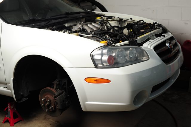
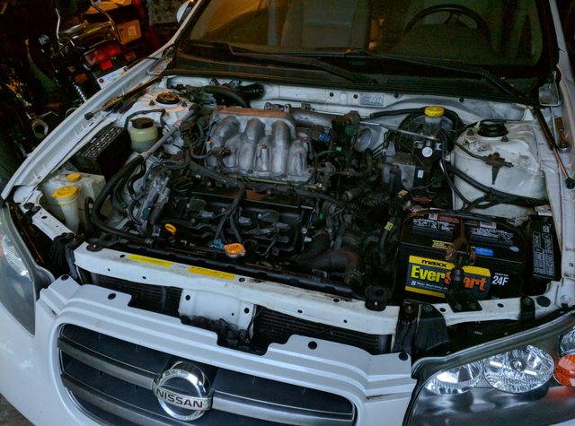
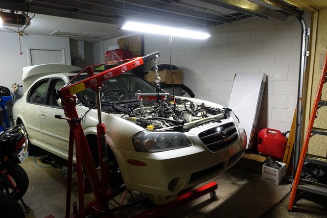
Just pulled the car into the garage, pulled the hood and airbox, getting ready to start the swap. Gonna jump in tomorrow and start draining the the fluids, getting things unbolted. I'll take pictures of the whole way, also going to get the new engine buttoned up.
Getting going on this swap some more today and tonight. Will be posting a fairly detailed list of what I'm doing and in what order.
Apologies that the photos on the underside don't have the same lighting, but i'm stuck using my smaller camera as I don't have the lenses or lights to deal with using my large Nikon under the car.
Today I've parked the car in the garage, put it up on jackstands (doubled up for safety) and removed the wheels. I'm going to start by pulling the hood, draining the fluids, and getting most of the wiring pulled.
I pulled the hood, by removing the four bolts holding it on, and removing one of the clips holding the insulation on the underside of the hood in order to access the tubing connector where the washer nozzle attached. I removed the hose from the T and tucked it away, then removed the hood and stored it in a safe place.
Next I removed the airbox and associated plumbing, leaving the throttle body attached to the intake manifold. The remaining tubing was disconnected, including the PCV at the valve cover.
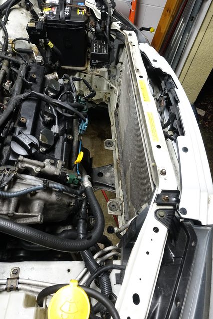
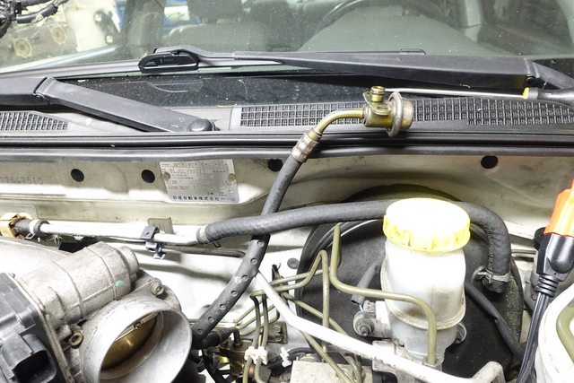
This gives a lot more room to work in the engine bay, and I wanted to get as much as possible before tackling a lot of the big unboltings, so I drained the cooling system and removed the radiator.
Started by removing the drain plug in the radiator with a PH3 driver and removing the radiator cap.
Once the coolant had drained from the system (took about 10 minutes), I removed the upper and lower radiator hoses, and the surge tank hose from the nipple beside the radiator cap. Some coolant will spill from the lower hose.
With the hoses disconnected, I disconnected the fan wiring as well, and pulled the radiator out of the car. Be sure to also disconnect the small clips holding the wires to the fan shroud.
Once those are removed, unbolt the two 10mm bolts holding the radiator supports in at the top, and remove them. The radiator can then be lifted out of the front of the car and set aside. Mine looks like it was replaced before, possibly due to a minor accident.
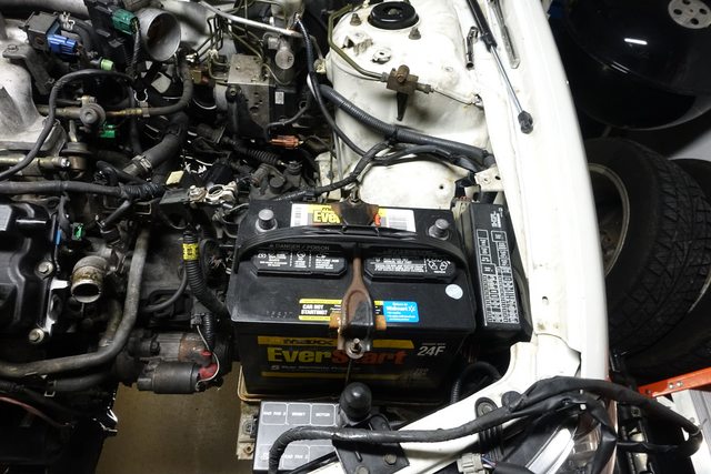
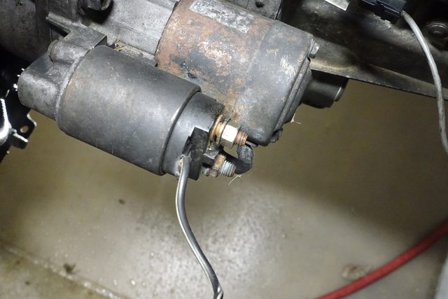
Next I removed the battery, disconnected the starter, and began working on the wiring.
Disconnecting both leads from the starter
Disconnecting the negative lead from the transmission. Helps to put these fasteners back to keep them in place, the onesy-twosey stuff.
It helps to remove the shift linkages on a manual transmission to reach the neutral shift wire.
Now I removed the wiring harness. I originally thought the harness wrapped around the engine like a belt, and the end couldn't be removed, however, it can.
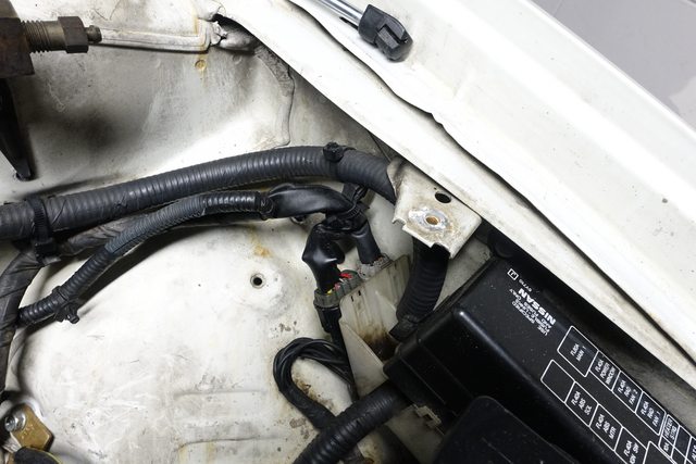
Starting from the driver's side, there are two connectors against the fender that terminate the harness. I started my unplugging here. Most of these connectors can be unplugged easier by using a screwdriver or other object to press in on the unlock tab, as they are usually pretty stiff.
Moving across to the transmission, there are a few connectors as well, and some clips that hold the wiring harness into the car. For nearly all of these I used needle-nose pliers to compress the wings of the clips and slide them out of their holes to preserve the plastic tie-downs, where possible.
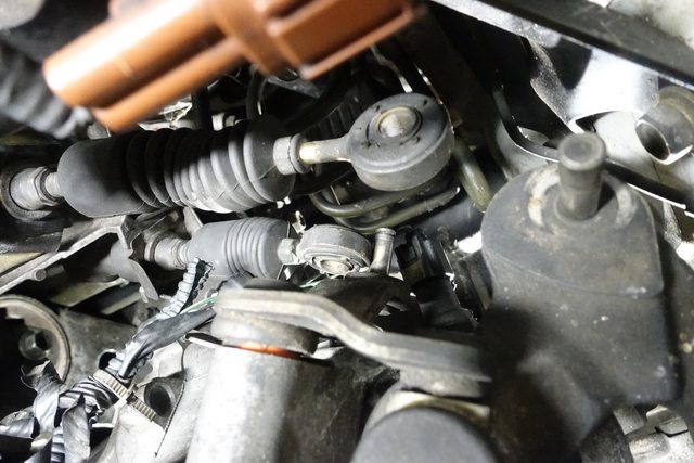
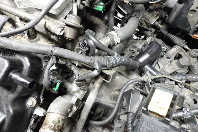
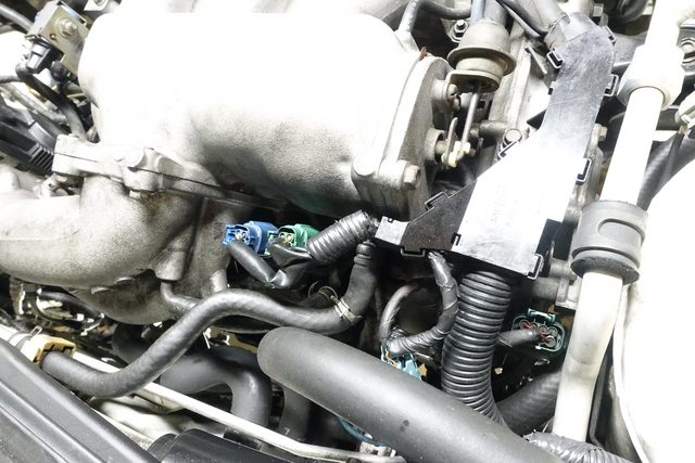
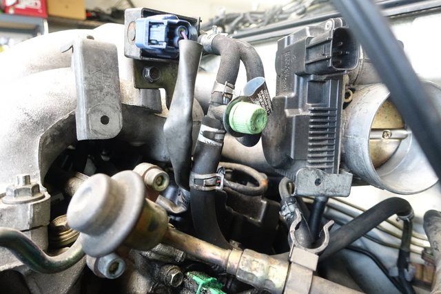
Towards the side of the engine, the knock sensor and a few other connectors are present. The knock sensor connector is a bit different than the others, and requires pushing the green part inwards, towards the sensor until it 'clicks' and then removing the connector.
More standard stuff here, unplugging injectors, coils, etc. It may help to label the coil wires, but not necessary.
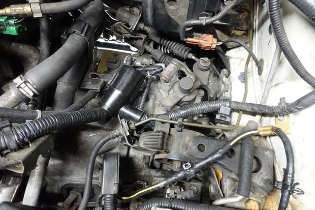
On the passenger side of the engine there are two grounds and the variable timing solenoids. The exception to the clip rule is here, the clip is threaded into the timing cover. For this clip I used a screwdriver to help undo the zip-strap and pulled the harness free.
On the back of the engine, there are three large connectors and one small, for the oxygen sensor.
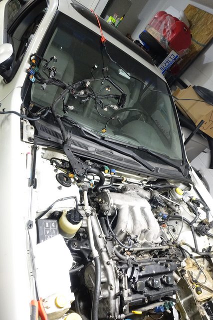
With all this freed, I was able to toss the harness up onto the windshield and out of the way of the engine.
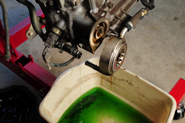
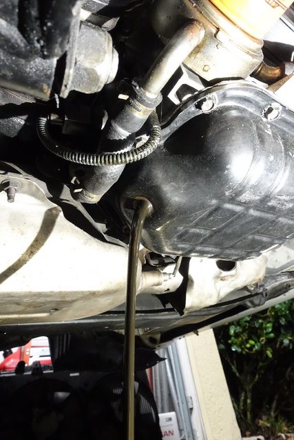
Next, I began draining the fluids. Need to get the oils out before working on tipping things around and pulling axles!
Started with the oil, drained it all out. it was completely black, very dark. Not sure if this was from the blowby of driving it a half mile with all the damage from the pre-cats, or just from lack of being changed, but with how the insides of the valve cover looked, I'd assume the former.
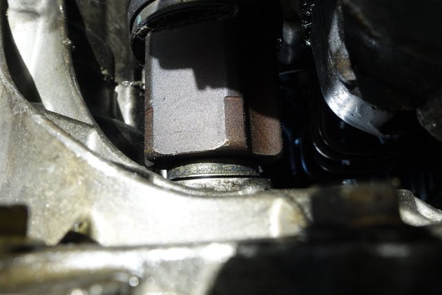
Next up, removing the transmission drain plug:
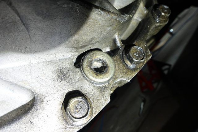
However, I found that they do not use hex for the drain and fill plugs, but Torx, and on top of that, some a-hole decided it would be a good idea to jam a hex socket in and try to free the drain bolt. It looks completely shredded.
(Mostly)Correct bolt appearance:
Drain bolt appearance:
I'm going to do some quick shopping tomorrow to try and find a larger set of Torx sockets to use, and maybe even some extractors to try and remove this drain. Looks like I'll be visiting the dealer again to pick up some drain bolts.
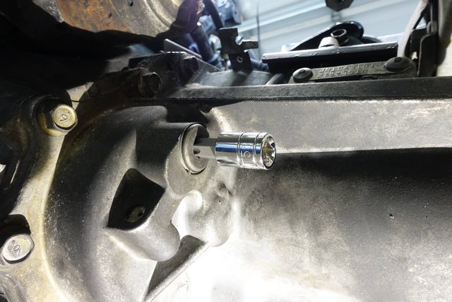
So, today I stopped by Northern Tool, picked up a set of large torx sockets (through T60), and a creeper to help save my back a bit. The goal tonight was to get the axles out. In order to do that, I had to accomplish draining the transmission.
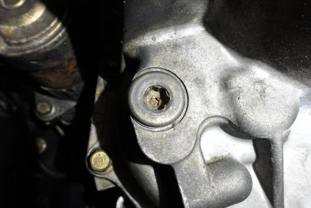
Knowing the drain/fill plugs were damaged, I stopped by the Nissan dealership to grab a few parts, including those, and of course, they had to order it all. Also found out they can't look up key codes by VIN for vehicles over 10 years old, i guess their system doesn't handle it? Doesn't make sense to me. Anyone know how I can get some keys cut from VIN? The one i got with the car is pretty worn.
As you can see, a T55 fits perfectly into the hole. These are T55 bolts, NOT HEX.
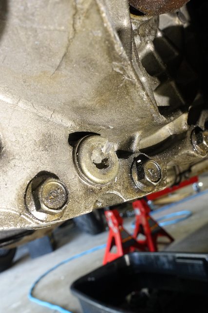
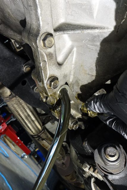
For the well-rounded bolt, I ended up having to use a die grinder to cut a slot in it, then put a cold chisel in and pound it with a hammer til it started to rotate. i was able to spin it out after breaking it loose. The upper fill wasn't as damaged, so I used the T55 socket and an impact wrench to break it loose.
Finally drained all the old oil out. Judging by the condition of the drain, this may not have been done when someone attempted to do it last.
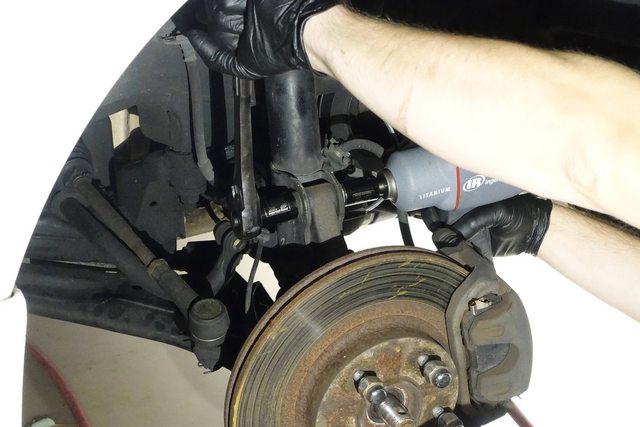
Next up was to try and pull the axle; according to the FSM all that's needed to be done is to unclip the ABS and brake lines from the holders on the strut, unbolt the strut from the knuckle and pull it away. This seemed to work.
Pulling the bolts for the strut.
Make sure you remove this clip and pull the brake line free of the strut before pulling the knuckle away, as well as the ABS wire! You dont' want to have to splice in another ABS sensor because you tore it off when trying to yank out the driveshaft!
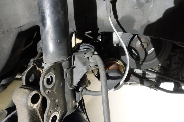
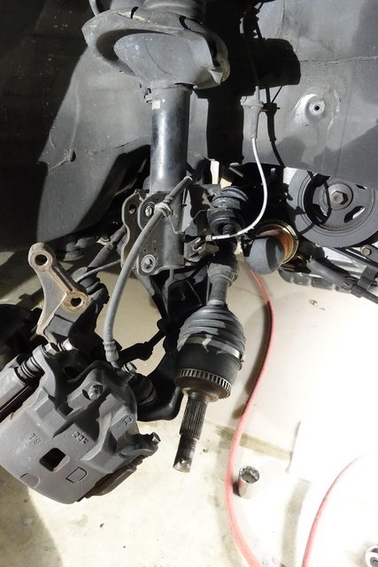
Finally pulled the driveshaft free from the knuckle/hub. Those of you with keen eyes will note the inner boot is broken and the grease has spilled out. I'm going to be installing new CV half shafts since they are both leaking.
The passenger side half shaft is held on by 3 bolts that screw into a flange attached to the driveshaft. Unfortunately, with the stock exhaust Y-pipe, it's nearly impossible to reach these bolts without building a complex stack up of extensions and swivels and attempting to reach from the driver's side transmission area. They are *buried* in there.
So, since i'm removing the exhaust anyway to pull the engine, and to replace the headers and Y-pipe with the OBX ones, I figured I'd just dive into the exhaust as well and get that pulled.
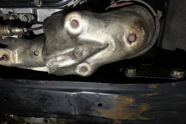
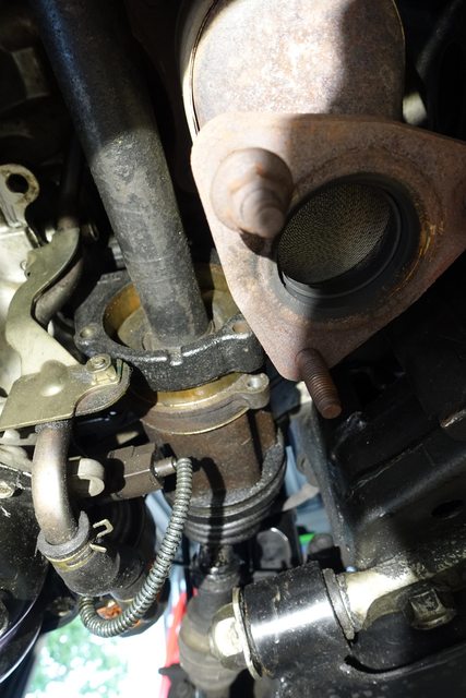
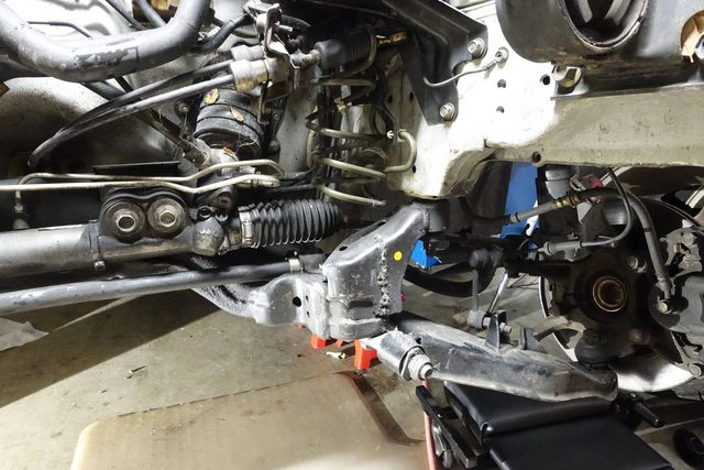
I started by removing the heat shield here to get access to the three bolts holding the front bank pre-cat to the Y-pipe
Once they were removed, the bolts are exposed. I hit these with some penetrating oil and let them sit for a bit before removing the bolts with my impact gun.
With those removed, I also sprayed and removed the bolts holding the rear bank cat to the Y-pipe. Two of the bolts weren't even fastened all the way!
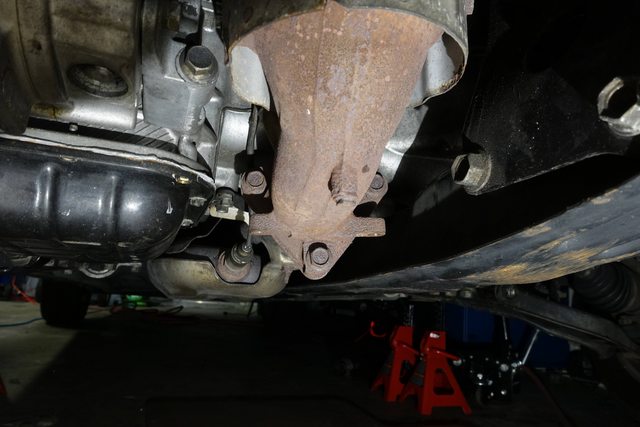
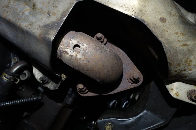
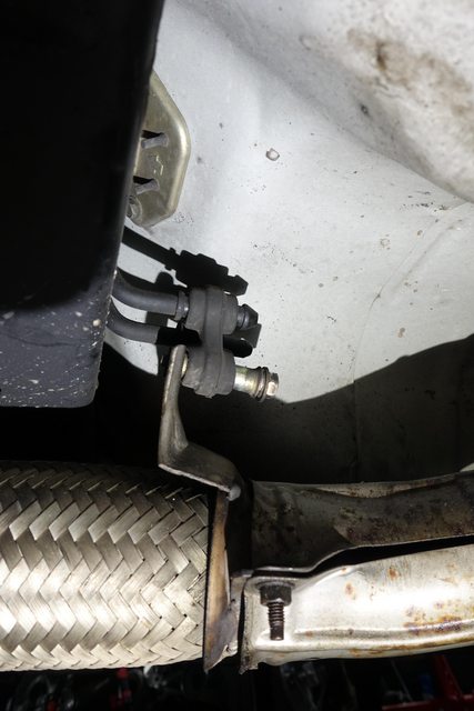
Finally, there are three things holding the Y-pipe in place now.
These two screws attached to the engine block where the pipe's curve is...
This rubber hanger,
and finally the two bolts attaching the Y-pipe to the cat. I sprayed and removed these as well.
Once all the bolts are removed, the pipe should move around a good bit. It took some pulling and shoving to get the heat shield to pop around the rear pre-cat enough to fit out, but once it did the rest came with it, and my car was free of the Y-pipe, with plenty of room now to work on the axle.
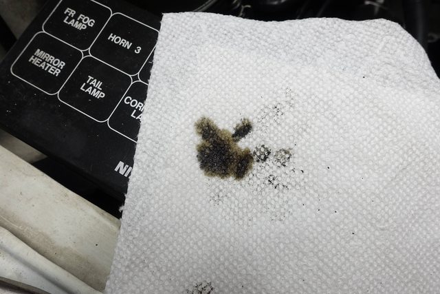
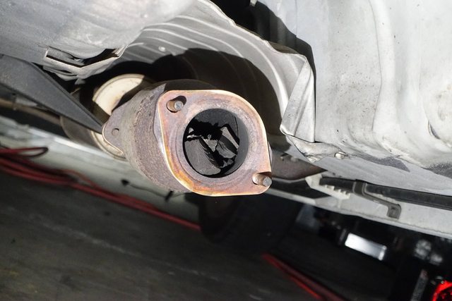
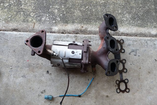
I decided to call it quits for tonight after having a long day of work and car work, but decided to take a peek inside the main catalytic converter after I got the Y pipe out. Big surprise what I found:
Yep. That's bits of front bank precat. Checked the rear bank, it's perfectly intact and solid. The front one seems to be the issue. confirms my theory a bit and just shows how bad the front precats really are on these cars.
I'll update again tomorrow with removing the half-shafts and hopefully getting the timing cover buttoned up. I should be closing in on getting read to pull the engine, which is good timing to have it done by the end of this weekend, depending on part lead times. (dealership and other items)
For most of the remainder of the work, I've been jumping around between different things, but I'll try and assemble it into something.
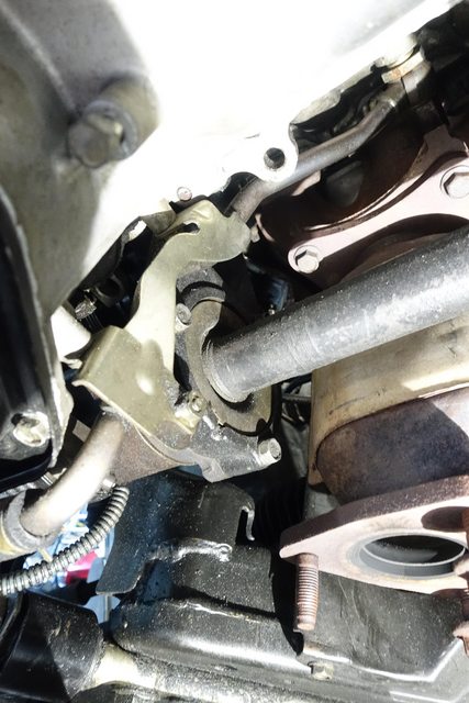
Now that the exhaust Y pipe has been removed, it's a lot easier to access the mid-shaft mounting bolts.
After removing those bolts, the midshaft slides right out, no prybar required.
On the driver's side, a prybar is needed, pry between the transmission housing and the CV shaft's housing. The shaft will pop out of the transmission.
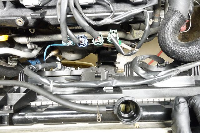
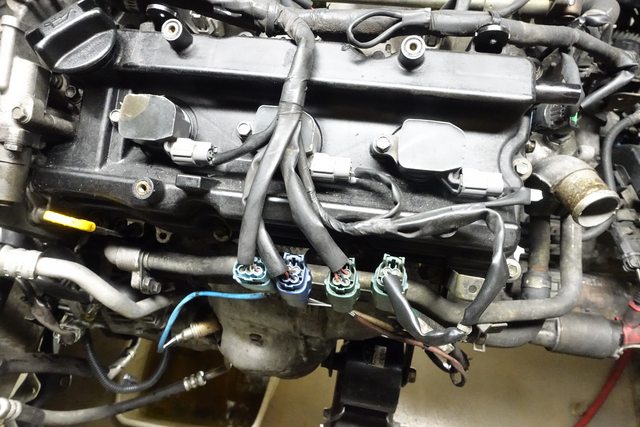
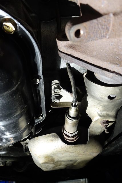
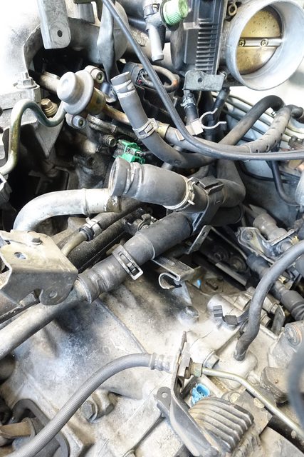
With the shafts out, I also removed the exhaust manifold from the front bank. You can see that the light blue connectors are for upper oxygen sensors, and the green connectors are for the lower sensors. Some penetrating oil overnight helped get them off easily.
I removed the Evap line, which feeds the intake manifold evap solenoid from the tank elsewhere, to burn off gases that evaporate within the fuel tank.
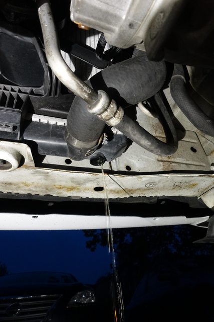
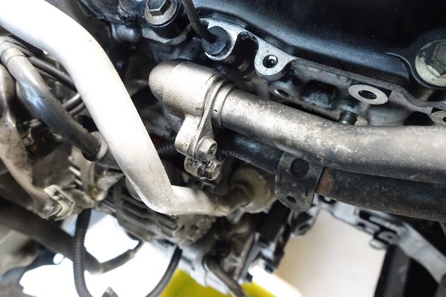
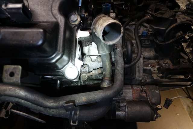
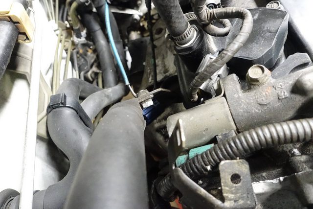
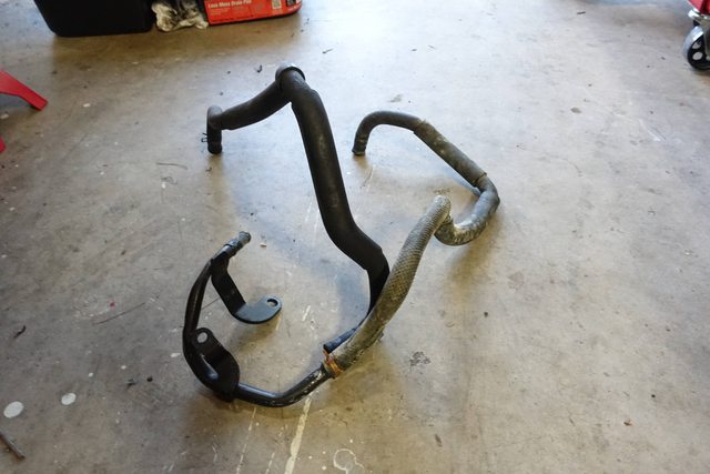
To drain the coolant out of the heater core before disconnecting the hoses, I first disconnected the lower heater hose from the coolant manifold here (upper hose in this picture):
I then blew compressed air through the other hose, which I disconnected from the other coolant manifold while directing the hard line into a bucket:
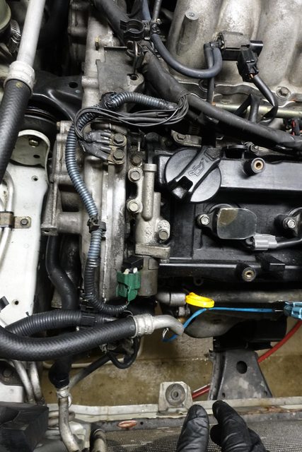
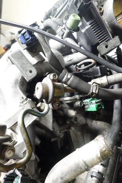
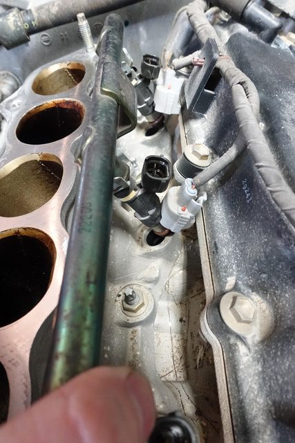
Disconnecting the fuel line almost last. There's a little fuel left in it, both the line and the rail. The screws are 5mm hex. I pushed the rail up under one of the vacuum lines against the firewall to keep it from dripping and getting in the way.
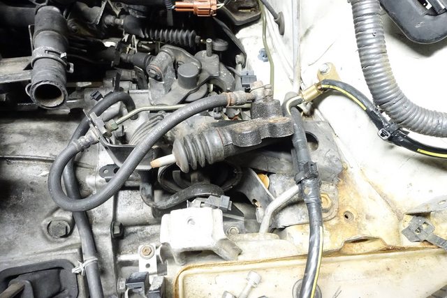
I also removed the clutch slave cylinder from the transmission, as it's going to need to come off to drop the trans. I set it off to the side, in the battery try after removing the clip that held the line into the transmission mount (I'll also be replacing that). It's held on with two 14mm bolts.
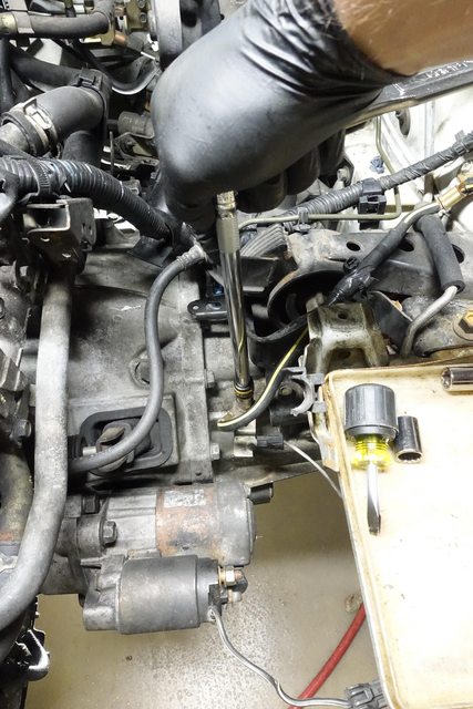
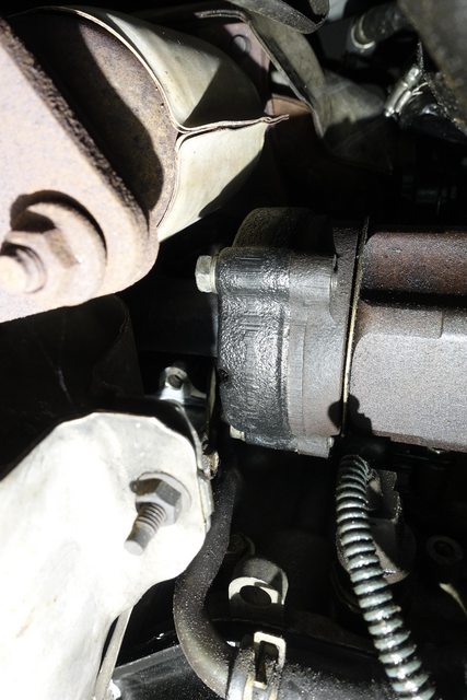
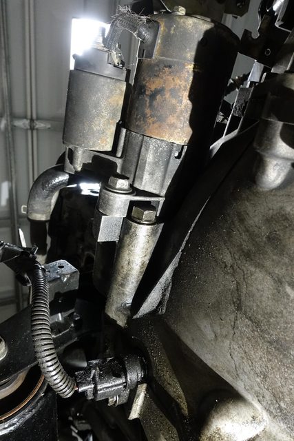
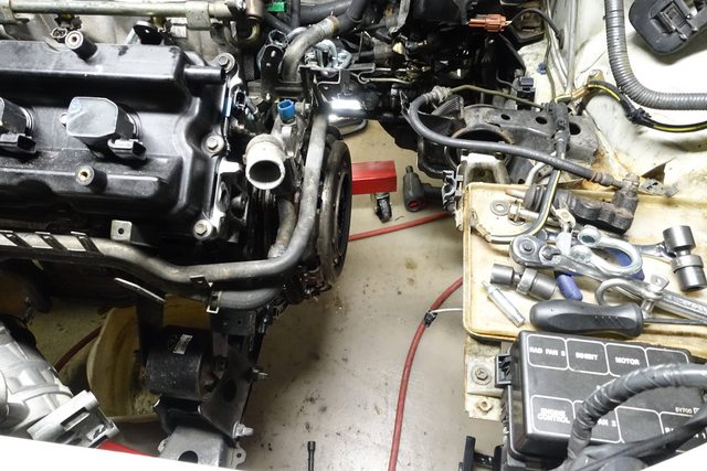
With nearly all of those things removed, the only things really left are the accessory drive items, and the transmission. I wanted to get the trans bolts loose to get it ready, but I noticed that the starter housing prevent access to one of the transmission bellhousing bolts.
So, the starter has to be removed in order to access the transmission bellhousing. I did that, and will probably replace it, as it looks like it's been through hell.
I should mention the crank sensor pigtail is removable.. i pulled it off to avoid any damage while moving the engine, as it's something you have to order from the dealer.
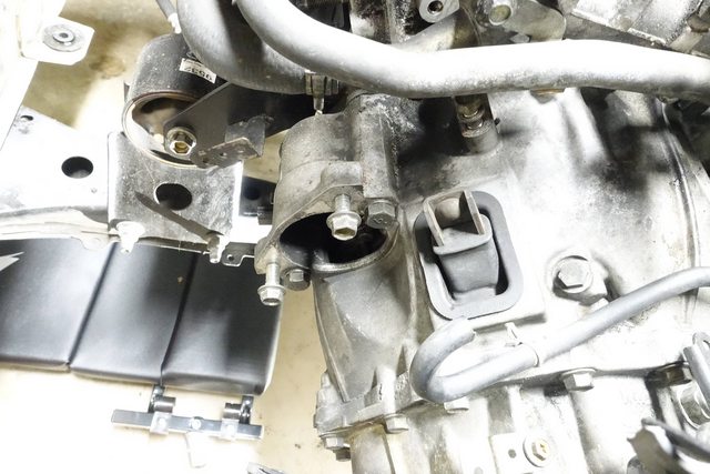
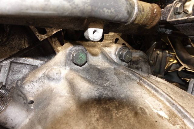
The transmission itself seems to be held on with 6 17mm bolts, and 3 14mm bolts. I loosened them with the help of my impact wrenches and a couple swivels and extensions to get into the tight areas around the frame and engine.
The 5 17mm bolts up top:
And the one 17mm and 3 14mm bolts down below..
So, that's all for tonight. I played around a little with the engine subframe but it seems to be not moving in the way I anticipated, so I'm going to try a different approach to removing the transmission. I'll continue updating tomorrow, where I'll hopefully have the transmission off and start working on swapping over the oil pan and other bits between the two engines.
I'll try and also show any differences between the engines themselves, other than just what pieces I need to swap over.
So, I was anticipating being able to drop the engine down low enough for the transmission to clear the body and slide out, before I had to disconnect everything from the engine, but that's not the case. The big issue is that I tried leaving the passenger side engine mount connected, but when it swivels down, the engine sits too close to the body and will contact the inside of the engine compartment before the thing is anywhere near low enough to come out. So, the only solution is to drop the engine down to remove it, which means pulling all the accessories at this time.
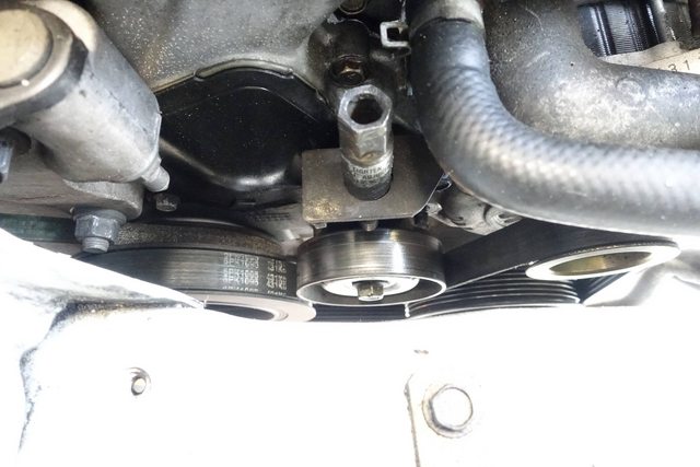
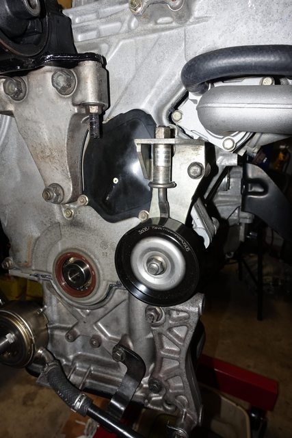
Loosening the belt is done by loosening the bolt in the center of the tensioner pulley, and then loosening the top bolt in the direction indicated on the bolt.
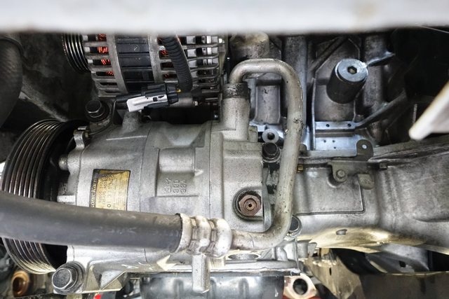
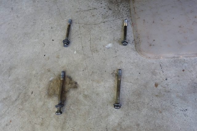
Then I pulled the AC compressor and strapped it off to the side. The compressor is held on to the mounting brackets with four bolts, the two with washers go towards the front of the compressor, and the other two go towards the back.
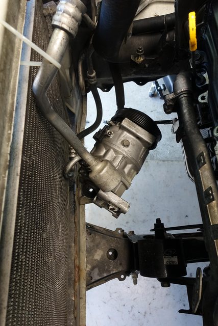
I strapped it off to the side against the condenser coils, with the lower hose resting in the gap to support it. this is a somewhat precarious position, but there aren't a ton of options down here.
Alternator was next, two bolts. One of mine didn't even have a nut on it, so not sure there. Someone had previously worked on it as it seems like it has been in a minor front-end collision, so it seems they did a crappy job. Anyway, with the two bolts removed, along with the output wire and the control wires, the alternator drops free. No pictures here unfortunately, but it's pretty easy to get to and anyone doing this shouldn't have trouble figuring it out.
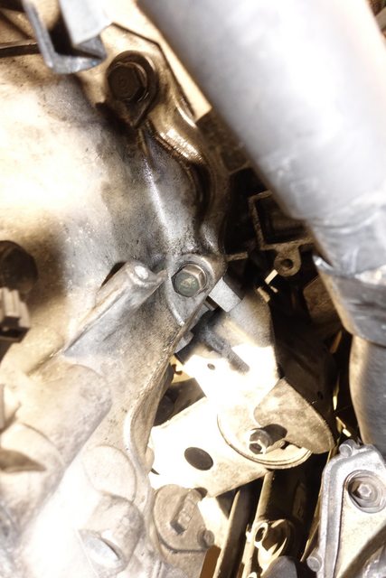
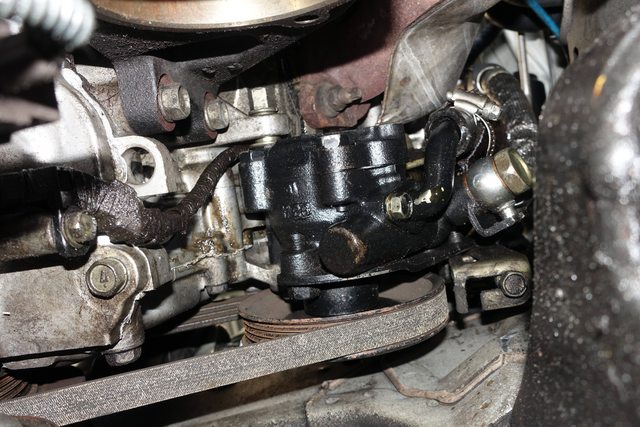
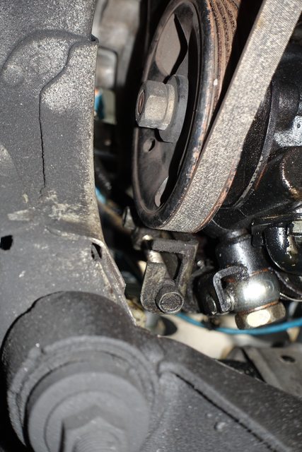
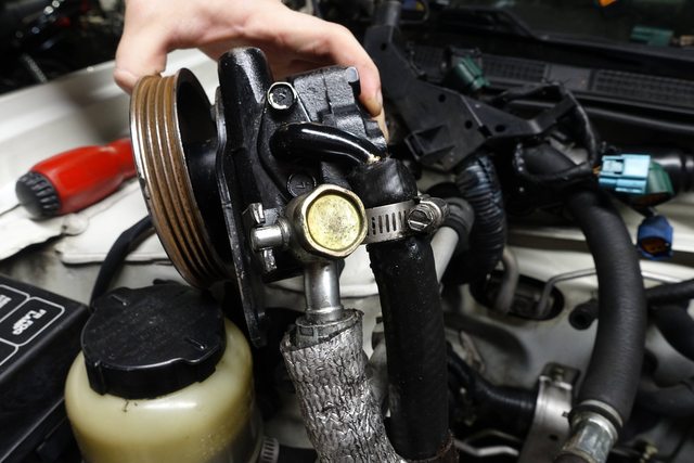
The power steering pump is a huge pain in the ***. It's in a tight location, there's almost no access to the bolts you need, and on mine at least, it's really crammed into the engine's mount points. I had to use a prybar to get it out.
You start by removing the main bolt from the back, which has a tall head. It took me a couple swivels and an impact wrench to get it out. You can see it in the upper left of this image.
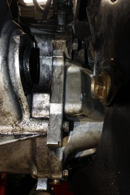
Then the harder part, getting at that little bolt all the way up there near the top of the bracket and getting it loose. I did that, loosened up the tensioner (which you have to tighten the bolt to do) and then removed the belt.
After that I pried on the pump for awhile, to find out that the bracket seemed to be in the way, so I wiggled a wrench in there to remove the support bracket. After pulling that out, I was finally able to lever the thing out with a prybar. You can also see in the above image, that isn't a stock hose. Someone just used a random length of too-big hose because the actual hose is $50 from Nissan, so one more thing I need to replace.
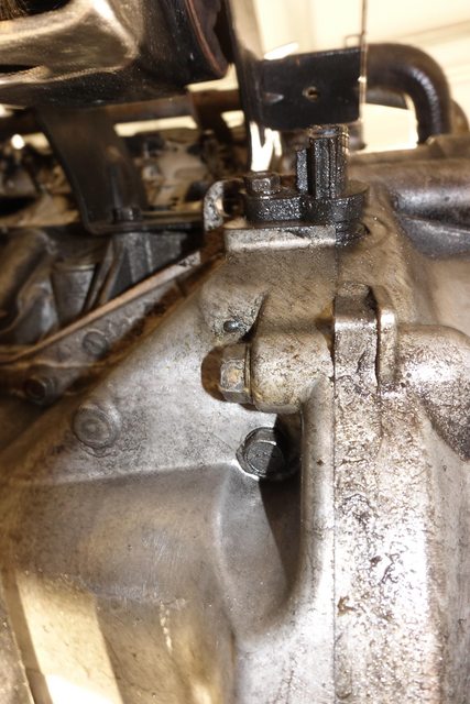
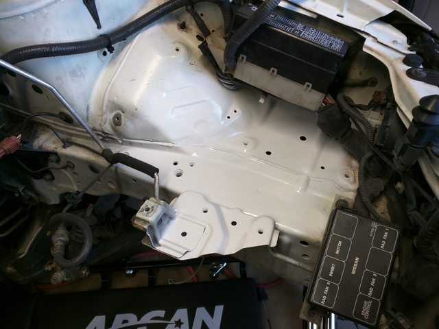
Don't forget to remove this little guy from the power steering pump line when lifting and lowering the engine, or the whole thing will be dangling from the power steering.
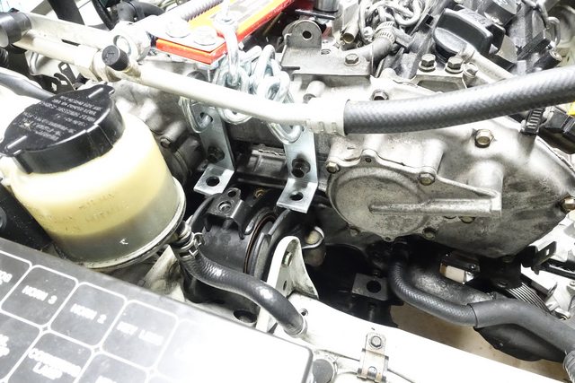
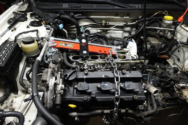
With everything finally disconnected from the engine, I proceeded to get the lift in there and chain it up. Make sure you take a good look around the whole thing before deciding to start moving it, the last thing that needs to happen is for a wiring harness or connector or hose to get bent/ripped off, and now you're replacing a lot more. I brought out a friend as a spotter to help watch the engine while I was moving it, and yell if he saw anything moving in a way it shouldn't, or getting caught on the engine.
Main issue here, on the other engine i'm using the two passenger side engine mount bolts, and the two top bellhousing bolts to act as lift points for the engine on the hoist. Here, with the engine in the car, I have neither.
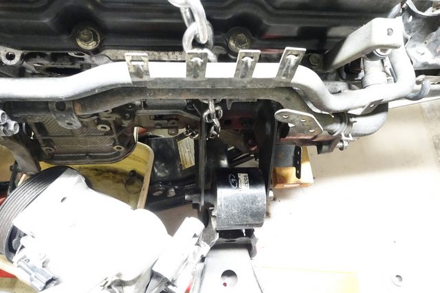
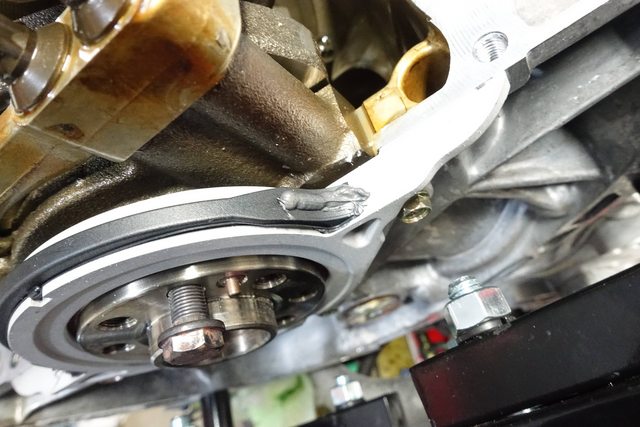
I improvised by using two large bolts that run through the opening in the timing case. While I know the timing case isn't super sturdy, it's held on by something like 23 bolts and that's enough for me.
Unfortunately, on the other side of the engine, I couldn't find any mount points that met the criteria of appearing strong enough to support half the engine's weight. I decided to say screw it, went and got a length of chain and another shackle, and just looped a chain around the other side of the engine. I ran it through the front engine mount forks to try and keep it towards the front of the engine, so it wouldn't slip back and cause problems.
One word of advice: make sure your engine hoist is extended all the way out for this job. You can never have too much lift or too much reach.. Stuff really needs to move around and I had to reset the engine back into the bay to move my lift arm out further. Just start with the furthest out, that way you'll have what you need. You really need to lift the engine high with the oil pans on, to get it to clear the car as well.
I should also add that pulling the upper intake manifold makes things easier at this point, less big honking intake taking up space to worry about, and things are just smaller/easier. Can see behind the engine easier to make sure there's nothing catching, for one.
I made sure I wasn't pinching any coolant or fuel lines, or sensors or anything else with my chains, and then jacked it up until there was tension on the engine, really until it was clear the car was relaxing upwards with the engine's weight off it.
(You can see that with how short the hoist arm is there's no way this is going to work. I can see that now. Don't make my mistake.)
With the weight of the engine supported, I slid a jack under the transmission and just lifted it slightly to help with some safety for myself. I removed the transmission mount bolt, so it could be freed from the frame. I then began to loosen and remove all the bolts on the transmission except for the top two.
Here's an overview of all the bolts that go into the transmission, in the order in which they go in.
Left bolts are 17mm socket (top/sides), right are 14mm socket (bottom)
After that, I unbolted the four large bolts holding the engine crossmember on, and the bolt from the passenger engine mount, freeing the engine.
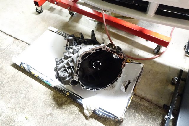
I don't have any pictures here of removing the transmission, because it was a bit of an ordeal. After removing the top two bellhousing bolts, the transmission slid slightly away from the engine, but just barely. I had my spotter control the engine hoist and push and pull on the jack under the transmission, while I wiggled, pushed, and used a prybar to slide the transmission off of the engine. It takes some shifting the engine up and down, and the transmission to be wiggled around until it finally slides free. It's not light, i'd say at least 100 lbs, so make sure you support it on a jack or something, don't try to muscle it out from the side or something, it'll just drop.
After the thing was finally freed, I lowered it down from the engine, rolled it onto a large piece of cardboard (double-corrugated, and double layers) and slid it out of the engine area.
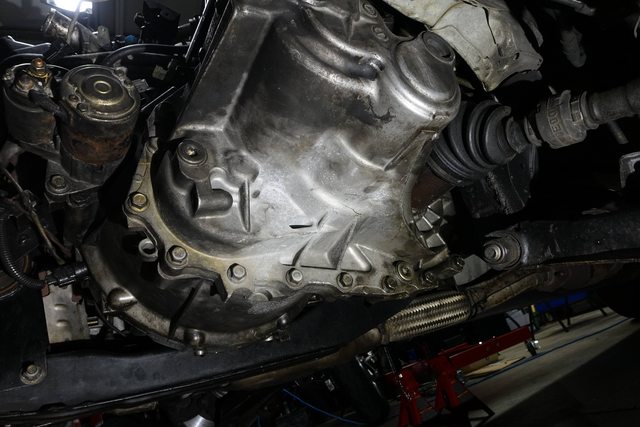
The dual-mass flywheel and clutch are now exposed to the world.
With that taken care of, the next thing to do was pull the engine itself, which is a bit easier now that the transmission's gone.
Nothing really to be said for it. Have someone watch the other side of the engine as you jack, watch carefully. I shifted the engine around in the bay as i lifted it, wiggling it around and watching for anything catching or still attached.
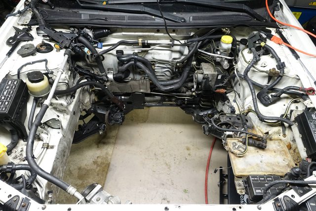
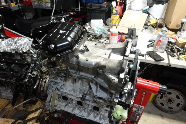
I just lifted it straight up, and pulled back, then lowered it onto the pallet that my new engine had been shipped on.
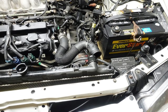
The engine bay looks a lot bigger without an engine in it!
Why did you remove PS/alty and manifolds? Leave everything attached except AC and tranny. The same goes for reinstallation.
And don't worry, the rear precat will fail, too. I remember one or two members gutted theirs from the bottom and they fell out easily.
Don't forget to replace the HP power steering hose and do it before you drop the motor in b/c that bracket has a learning curve (long needle nose pliars and a longer bolt make it easy) LMAO
Last edited by Child_uv_KoRn; 05-22-2016 at 02:03 PM.
So, this is just a quick post with some random observations i'm making now that the engine is out and I can see a lot easier into both the engine compartment, and the old engine itself.
It seems that the front main seal was leaking. In these cars, the front main seal seals against the crank pulley assembly, so if it starts to go, oil will leak out of there and spray a line of oil just inside the inner fender area on the passenger side, so that's a good way to see a leaking seal.
My CV joints were completely toast. One had a completely torn/separated boot, the other was beginning to slip back, and it had leaked out all it's grease. You can see the line of grease that was slung out against the subframe and LCAs.
The power steering suction hose is NOT standard. It seems that someone grabbed a random length of hose and just hose-clamped it onto the pump and reservoir. It's leaking a little too. This is not cool, and while I know the hose is some $50 from Nissan, it's important to me that this thing not leak, especially with how much of a pain it is to get to. I'll just bite the bullet on this one.
The transmission mounts between the 5-speed and 6-speed are TOTALLY DIFFERENT. Just because a mount says 'standard' doesn't mean it's for the 6-speed. The 6-speed uses an angled mount, while the 5-speed uses a flat mount. Now I need to send a mount back.
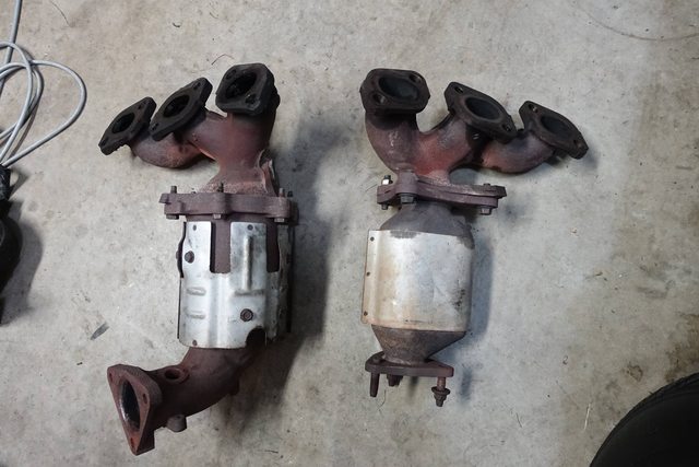
Front and rear cats are totally different, which makes sense why the front would go and the back wouldn't.. they aren't the same thing at all.
I'm starting to swap things over from the old engine to the new, so I'll post stuff on that next.
Why did you remove PS/alty and manifolds? Leave everything attached except AC and tranny. The same goes for reinstallation.
I was just going off a couple threads/videos I'd seen about swapping, the idea being it made it one less thing to drain/refill, but good to know about the alternator, i'll try and mount it up to the new engine before dropping it in.
Don't forget to replace the HP power steering hose and do it before you drop the motor in b/c that bracket has a learning curve (long needle nose pliars and a longer bolt make it easy) LMAO
Sounds good. Do you replace the whole assembly with the sensor plug and everything up to near the strut tower?
I was just going off a couple threads/videos I'd seen about swapping, the idea being it made it one less thing to drain/refill, but good to know about the alternator, i'll try and mount it up to the new engine before dropping it in.
Sounds good. Do you replace the whole assembly with the sensor plug and everything up to near the strut tower?
Quick note to any of you watching, I haven't abandoned this! I've been working day and night on getting the engine back inside, and it's been a task! I haven't been taking as many pictures as before since a lot of it's just simple reassembly, but I've got a lot of comparison pics and some gotchas that are happening when switching up to a newer engine.
Rest assured, I will keep this going, but I've got a couple work deadlines I need to meet and so I'll get back into this as soon as I can!
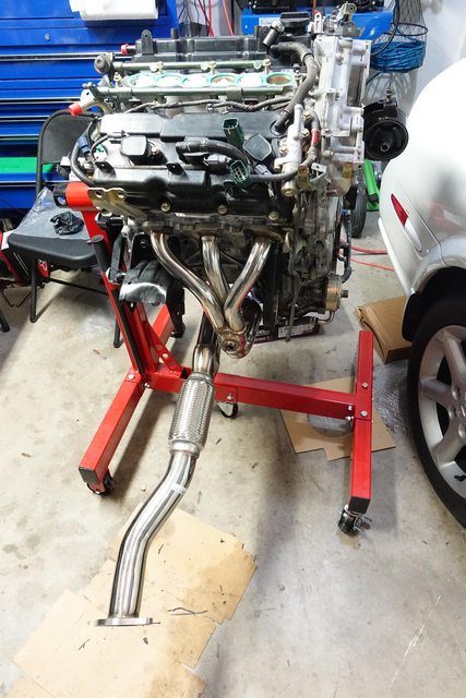
Here's a pic of mocking up the OBX headers on the new engine!
Quick note to any of you watching, I haven't abandoned this! I've been working day and night on getting the engine back inside, and it's been a task! I haven't been taking as many pictures as before since a lot of it's just simple reassembly, but I've got a lot of comparison pics and some gotchas that are happening when switching up to a newer engine.
Rest assured, I will keep this going, but I've got a couple work deadlines I need to meet and so I'll get back into this as soon as I can!
Here's a pic of mocking up the OBX headers on the new engine!
Did you do the 2ndary timing chain and tensioner shoes on the 6th gen motor? I hope you did because most of those engines I see over 80k has that annoying chain whine..
I had an 05 engine in my 02 and lasted 4yrs or so timing chain Rattle was terrible caused the engine to jump timing.... swapped I'm a 08 max engine last August it's been the best engine 07-0 do not have issues like the 02-06 do with the oil burning and chain issues.....you seem to be putting in alot of hardwork wish you the best my friend
Alright, so apologies for the delay in this build, but I've been away on work, getting some things in order at home, and generally doing a bit of relaxing after this. Work's been busy, right after I got back from a trip I had to get some projects completed, so haven't been around much to get this finished, and I'm a bit lazy. Good thing I took some (mostly decent) notes!
Hopefully I'm starting back up where I left off, and I can get all these little gotchas in here so someone doing the same thing will get some good info.
So! Where I had left off last, was yanking the old engine out of the car. This is pretty simple once you get the transmission off and everything disconnected. I ended up pulling off the accessories, but at the suggestion of a couple posts here, it's easier to leave them on. I'll believe that with the alternator, but the PS hoses would be a bit of a mess/pain to take off while the engine's still in, so I'd still believe it would be easier to pull the PS pump off the engine and out of the way while lifting the engine out of the bay.
The big deal with this is that the service manual mentions you should pull it out from the bottom, essentially lifting the car up off of the engine itself, which would be totally simple, but being that I do not have access to a lift, the cherry-picker method it is. I did some contemplating, and I don't think it would be an easy task to get the engine out/in with the transmission attached, due to how tight the whole thing sits inside, especially with the protrusions from the driver's side and with the little clearance you get on the passenger side. So, I elected to drop the new one in without the transmission as well..
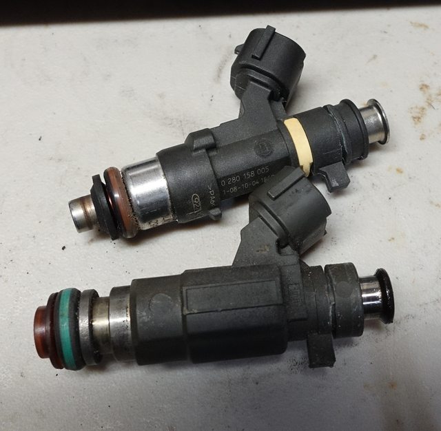
With the engine out, I started the process of swapping parts over from one engine to the other. I started with the top of the engine, pulled the fuel rails and swapped over the injectors from the new rail to the old one, since the old rail has the proper hookup to the fuel hose coming into the engine compartment. The newer style uses a special connector style which needs a tool to disconnect, while the older one is just an o-ring and a couple hex bolts.
I swapped the injectors in, using new o-rings on the top of the injectors, since that's where the pressure is.
This pic shows the new injector on top, the old one on the bottom. Both are missing their upper o-rings.
The rail didn't seem to fit in easily on the newer lower intake manifold, so I needed to carefully bend the tubing slightly to make it fit. Not sure why this was, but once I did that, everything fit up nicely.
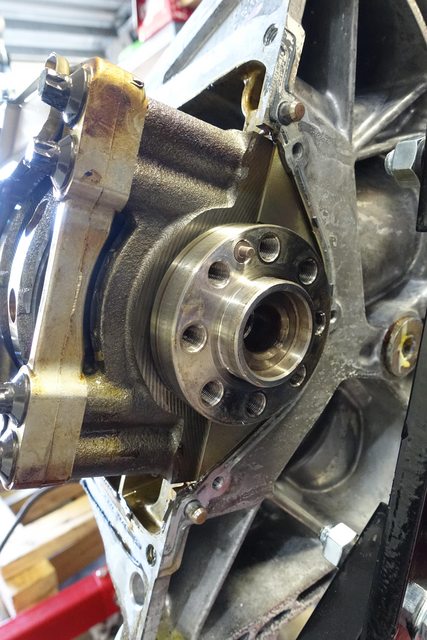
Pulled the flex plate off the new engine, and removed the rear main seal to replace it.
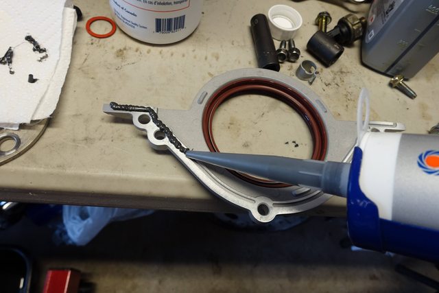
The new seal came as the whole aluminum plate with the seal installed in it already. I went ahead and made sure the surface on the crankshaft was clean and smooth, oiled up the new seal, and laid down some Ultra Black RTV on it.
Once complete, reinstalled, making sure that the seal sat properly on the crankshaft surface, and that it slid completely in. Once again, followed the instructions on the Ultra Black to run the bolts in until it began to ooze out, wait one hour, then torque to spec.
Next up was to remove the old oil pan from the old engine, as I needed to transfer it to the new engine to support the manual transmission.
I removed the lower oil pan and all the bolts from the upper oil pan. Here's the bolt pattern from the 6-speed HLSD on a 2002 VQ35, notice it's different than the one used on the newer automatic engine earlier in this thread. The bolts need to stay with the oil pan, in fact, basically anything bolted to the oil pan, should stay with that oil pan. This includes the oil cooler, associated tubing, bolts, etc.
Once those are removed, I used the convenient pry-slots with my pry-bar to remove the pan. Keep in mind there are dowels inside, so I got it started on that side by breaking free the RTV, then worked it back and forth from either side to rock it off without bending/damaging the dowels or their holes.
Went through and cleaned out the old oil pan thoroughly, and removed the baffle from inside to clean that out as well. Found an interesting thing.. On the newer 2005 engine, the oil pan baffle has been moved to mount on the engine itself, whereas on the 2002 it mounted inside the pan. Since the 2005 is a newer design, I decided to go with that one, and left the baffle off.
I also took the time to clean off all the RTV on the old oil pan, making sure things were very smooth and clean, both inside and out of the oil pan, since this is such a good opportunity to clean things up. I probably could have done more cleaning, but It's been a tiring ride.
I found a putty knife/scraper tool works great to get this stuff out.
They look sorta like this:
It also works to pound the pointed end in between the lower and upper oil pans, to get that thing loose, especially after it's been RTV'd in, and you plan on reusing it (don't want to bend that metal around). Make sure it's flat against the sealing surface, don't want to ding that up either!
Following the FSM, after cleaning the crap out of the engine side of the upper oil pan gasket surface and rotating the engine so things would be easier to access, I laid down a bit of RTV on the points specified...
...and then installed the seals, which I then applied more RTV to in the appropriate place. ***NOTE***
The FelPro 'Timing Cover Gasket Set' (TCS45997) which includes an oil pan seal, does NOT contain both front and rear seals, only the front. You'll need to get kit OS 30696 to get both seals. It includes RTV as well.
I procured two new OEM oil filter passage seals which go on the oil pan from Nissan, but I believe the oil pan set comes with those as well. Mine were orange from Nissan, FelPro's are black. I'm sure they work in a similar manner.
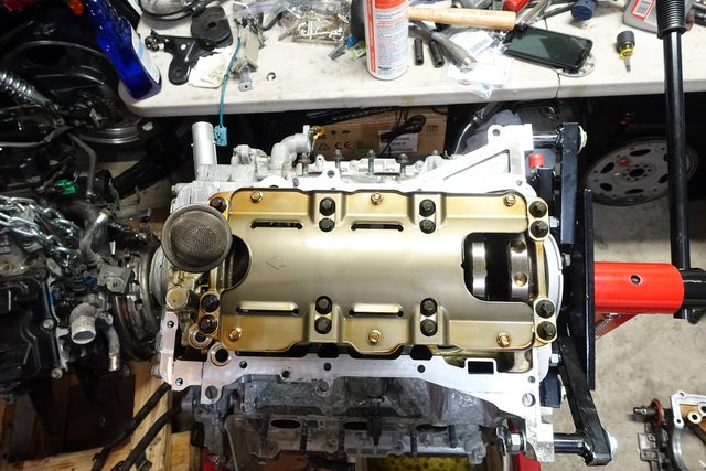
With that done, I fully applied RTV to the oil pan, in the method prescribed by the FSM, and lowered it carefully, with the help of a friend, onto the engine, aligned it and set it in.
Following the Ultra Black instructions, once again, installed the bolts, hand-tightened til an even amount oozed out from around the oil pan, waited one hour, and torqued it down. Got a little overzealous here and decided to put the lower pan on, but forgot that I had to torque bolts INSIDE that area after the RTV set, and so had to remove it again. Luckily I had used a FelPro oil pan gasket there, so did not have a mess of RTV to contend with.
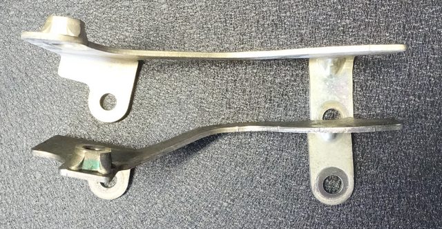
Complete! The oil pan is reinstalled, torqued, and ready to rock! You may notice I have the support for the coolant line installed here as well, I found out that they differ between oil pans and so cannot be shared. Once again, parts attached to the oil pan must follow that oil pan to the new vehicle. The upper oil pans, while sharing bolt patterns, seem to be of quite different shapes and so were not compatible, as the attached parts had been modified to account for these differences.
An example, the coolant tube support bracket. Notice the subtle difference in the shape of the bracket, making these incompatible.
Next post, I'll move on to cleaning up the engine bay, replacing the power steering hose, and getting things prepped to drop the new engine in.
Continuing on from last night's post, more info on prepping the engine and getting things reassembled:
A few more pics demonstrating the difference between the auto and manual oil pans:
Lower coolant hardline to oil cooler (manual on top)
Oil cooler (manual on right, IIRC)
Front oil cooler coolant pipe (Manual curving towards left)
With those attached, I swapped over the engine mounts (relatively easy) and the few remaining brackets which hadn't been moved over. No point in showing these, just a bolt or two holding them on.
I cleaned and reinstalled the AC/Alternator belt tensioner, with a new pulley/bearing. A note here, we had to shave down the front cup on the pulley as it was scraping against the new pulley every so slightly.. about 1.5mm worth. Removed a bit of the edge and it works fine.
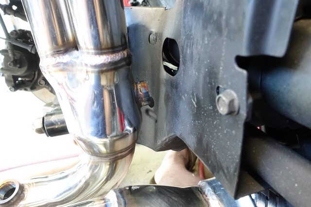
Test fit up the headers in the area to see how they'd mount. It's clear that OBX intended for the o2 sensor to fit through that little hole there, but I'll be damned if anything is gonna fit in there, shield or not. It's a mess. I elected to weld a bung to the passenger side of the headers as many others have.
Unfortunately, due to the lack of things available to me, and my drive to do everything myself, I ended up attempting to weld the bung on with a stick welder, and burnt through the pipe in a couple spot. I had to weld these up as well, making a huge mess and one of the worst looking welds of all time, which I will not be showing here. (unless people wanna see it). However, it seals, and that's all that counts.
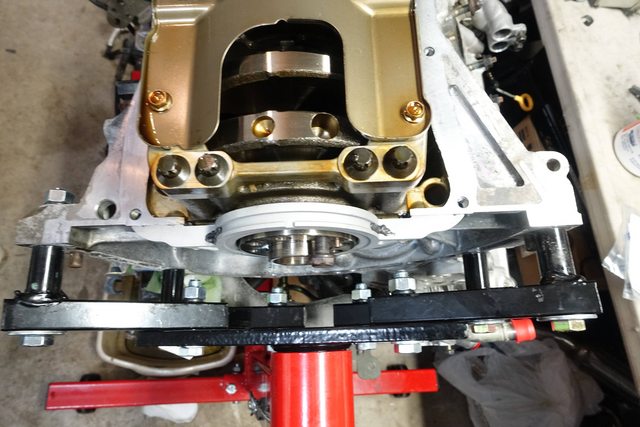
One of the last things to get installed was the flywheel. The issue here is that the newer engine, while having the same bolt pattern on the crankshaft, uses shorter, hex-head bolts to hold the flex plate to the crank, as it is a thinner piece of metal. The flywheel on the manual-transmission engine is thicker, and so has longer, T-55 bolts holding it in. I needed those longer bolts in order to affix the new Fidanza flywheel to the crank.
Quick pic of the test-fit of the flywheel:
Now, the new flywheel came with a pilot bushing, however, by my calculations, the transmission does not sit far enough into the engine to actually have the input shaft touch this bushing, nor does the tip of the input shaft have a turn-down for a bushing. So, the bushing's only purpose would be to hold the clutch alignment tool in place. I decided to install it anyway, to help with clutch alignment.
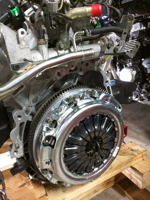
New Exedy Stage 1 clutch, ready to install:
Lined up with the installation tool, and installed:
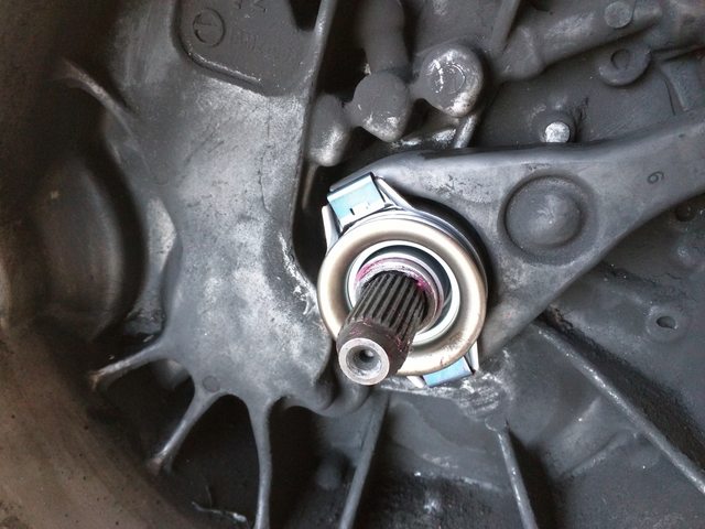
Decided to go ahead and put the transmission on after installing the engine, but I also went ahead and cleaned up the inside of the bellhousing a little bit, and installed a new throwout bearing.
Went ahead and cleaned up the battery tray area, as it's clear a battery overflowed once here and ate away at the paint, leaving rust and some nastiness behind..
Took the battery tray, used a die grinder and flap wheel as well as a brown 3m surface prep pad to clean up any rust spots on it, then washed it clean and laid down some white primer, and then a coat of white enamel. Hopefully that'll help keep things looking a bit better.
Cleaned the engine bay up with Purple Power and water, and an old tire brush to cut a lot of the grease and make everything look a bit better than it did with the old engine. Checked that nothing was leaking.
I then went ahead and took care of the power steering pump and hoses.
Here's the power steering pump as it was in the engine:
As you can see, the suction hose is not standard, and things are pretty nasty. I disconnected both hoses, drained them and the pump, and got the pump housing all cleaned up.
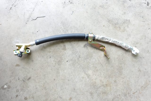
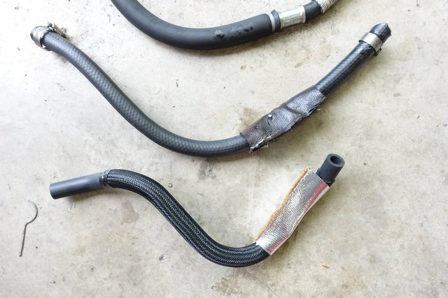
Procured a brand new power steering hose from the dealer (at a cost of $270), here it is:
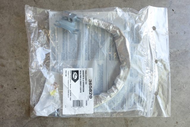
Also bought the Gates brand hose, which doesn't appear anywhere near as robust as the Nissan one. I'll be returning this.
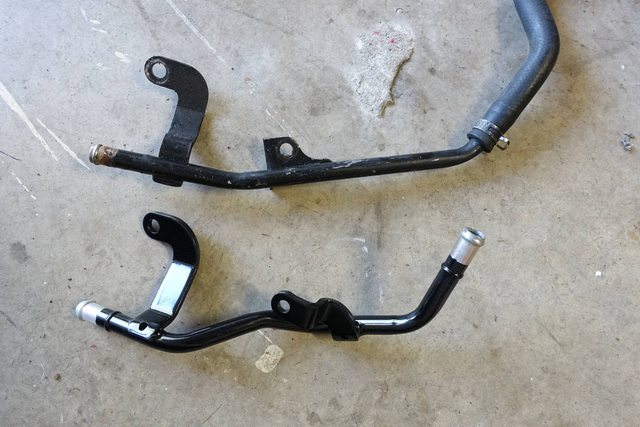
New and old suction hoses (old top). Clearly it's just a random length of hose cut and clamped to make it work, but shows the difference in bends and sheathing, also the old one was too large and was leaking.
It was relatively easy to get it installed, but I did attach the power steering pump to the engine before installing it. Another thing I did to make installation easier, is that during my test fits, and when I removed the PS pump from the engine, it was wedged very hard into the space and I had to use a prybar to remove it from the engine. I took my die grinder and removed about 0.5mm of material with a sander disc to make it fit better, and it helped immensely, giving it a smooth, but correct, fit.
Make sure you get new copper crush washers for the high pressure hose. I'd also suggest making sure you leave the mounting bracket attached to the hose, as it's a real pain to get back on once it's been taken off.
As far as bleeding the power steering, I attempted to do the instructions here on the forum to 'dry bleed', where you run the wheel back and forth while the engine is off and the front end is off the ground, til there's no more bubbles. However, bubbles never stopped coming out of the piping. Eventually I just gave up, as the FSM states "until the fluid level stops lowering", which it did within the first 10 mins of bleeding it. I haven't had any noise yet, so not sure if that's just due to using the Nissan hose, or because of the bleeding procedure, or both!
Another note.. I replaced the front metal coolant lines that carry coolant through the side manifold and to the heater core, and the newer spec parts did not have all mounts for the O2 sensors as the old engine did. This wasn't a huge deal, but something to be aware of.
After I got everything mounted up that I needed to, I got the engine back up on the hoist and ready to install. Managed to gouge one of my fenders with the flywheel even being careful, so i'd make sure you have everything way up in the air before sliding the engine inwards.
Once I got the engine lowered into place, I used the extra room I had in the engine bay before things were locked down, to install the power steering hoses as it was easier to access that area with the engine away from the firewall.
With that finished, I started by getting the passenger side engine mount resting in it's holder, before working on getting the transmission attached. It required three people to help, one operating a jack and pushing the engine, another lifting from the driver's side, and myself, bench-pressing the transmission and guiding it inwards onto the spline shaft and dowels. After about 15 minutes of work we managed to get it installed.. I don't have any pictures of this process for obvious reasons, but suffice to say it's a fair amount of work, making sure we didn't hang the transmission on the clutch plate, which can cause damage.
With the transmission in, I left the engine hoist in place, and installed the transmission mount, got both passenger side engine mount and transmission mounts attached to the engine, and set a jack up beneath the engine to support it while I removed the hoist. This was important as the two mounts aren't really made to hold up the whole weight of the assembly.
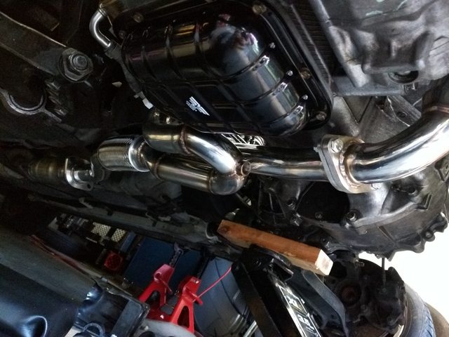
The headers went in fairly smoothly. I know a lot of people mentioned they had to cut the center support or remove the rear engine mount shield, but I didn't have those issues. I DID have to remove the rear engine mount from the block and have the center support removed in order to install the headers. Once they were installed, I reinstalled the rear engine mount and center support. I attached the exhaust, loosely, letting everything able to shift about until I began torquing down the headers, starting from there I worked my way back, torquing as I went until I reached the rear catalytic converter bolts. I do hear a rattle though, so I will investigate and report back, but after initial installation I did not see any clearance issues.
(You can also see the newer coolant lines here)
Lower Y pipe and headers installed
With those installed and torqued down, I began installing the rest of the difficult-to-access bits under the engine, and the installed the center support so that I could remove the jack. I then installed the rest of the connections, coolant, fuel, electrical, etc. I cleaned all grounds, reamed all tapped holes and used electrical grease to help prevent corrosion on the terminals.
A couple notes here. I found out that the 2005 knock sensor is not compatible with the 2002 ECU and cable. The 2002 pigtail for the rear bank camshaft sensor must be re-used, as well as the knock sensor wire, as the 2005 harness combines these, wheras they are separate on the 2002. I ended up purchasing replacements for both cables from Nissan, as the connectors had become brittle and broken over time.
I tried using a replacement Dorman knock sensor/cable combination I found on Amazon, but it cause a CEL, throwing a knock sensor code. Using the correct knock sensor with the Nissan wire fixed it. Someone on Amazon mentioned needing to swap polarity on the new knock sensor, but I wasn't about to fool around with these cables.
For the O2 sensors, I used new factory sensors in all locations EXCEPT the sensor that connects in the rear. I had to extend that sensor, and to do so, used the recommended universal kit from Bosch. This kit uses some special connectors to splice the wires, as O2 sensors pull make-up air in between the wire strands themselves, so if you solder them, it will prevent the sensor from operating properly. These splices utilize screw-locks to hold the wires in place, which allow air to flow through the sensor wires as normal. I hooked it up following the directions, (while leaving the wires longer than stated) and it has worked perfectly so far.
I basically worked in order, reinstalling the wiring harness, reconnecting everything where it went, double-checking all connections and bolts to make sure they were tight, making note of which things needed to be torqued or which had to be reinstalled before I got on with starting the engine.
I reinstalled the new axles in place, and found that the driver's side axle was giving me trouble, would not turn when at full-droop. Not sure why, but when lifted up a bit it ran fine. Decided to just go with it, if it blows up i'll just take it back to the parts store.
Installed the new oil filter, torqued down the drain plug, filled the engine with oil and checked for leaks. Reconnected all the hoses for the cooling system and began filling that, checking for leaks the whole time.
Started up really loud at first due to the oil pressure not being built up in the timing chain tensioners, but once it started spinning for a few seconds, it quieted down. The loud exhaust noise was from me forgetting to tighten down the bolts on the catalytic converter. Once I did that it quieted right down.
Further things that I did was to install some spacers on the downstream O2 sensors to space them up out of the stream. This has worked great to keep the CEL off. It doesn't stink because I still have a high-flow cat in the exhaust system, and cat-back is stock.
So far I've been lucky, no coolant or power steering leaks, and only a tiny oil leak from the lower oil pan, since I didn't use RTV. Going to fix that up with a little extra torque on the bolts in that area.
Other than that, it runs great. While the knock sensor was throwing a code, the car was in a limp mode, and had terrible performance, but once that was cleared it ran amazing. So far, things are going well, the only real downside is some clutch shudder from the extra grip that the stage 1 material seems to have. I've just modified my engagement point and make sure to engage the clutch a bit more aggressively than I would have on my other cars and it doesn't shake.
So, I consider this to be a success! I'm going to go back and edit a few things to add some more info, but it's the biggest project I've ever undertaken on a vehicle, and has been really worth it. There's a few small things I need to take care of, like a buzz at a certain RPM from the exhaust, and that tiny oil leak, but aside from that, I'm ready to get another 200k miles out of this car.
I'm sure I'll be posting some more how-tos in the future, and I'm sure there's things I've missed here, mainly on the reassembly, since the project was really wearing on me and I just started trying to get things back together, but really if you use the FSM as a general guide and make to-do lists, bag your parts/fasteners well, use the proper tools and fluids, and torque things to spec, it's not a terrible process. It's quite complex, yes, but more tedious than anything.
Feel free to comment on things I left out, stuff I may have overlooked, or if there's a better way to do things.
Nice job and great write up! You my friend must live in one of those friendly climates that doesn't get snow/ice in the winter and doesn't use salt on the roads. Everything came apart seemingly so easily. So jealous.
Nice job and great write up! You my friend must live in one of those friendly climates that doesn't get snow/ice in the winter and doesn't use salt on the roads. Everything came apart seemingly so easily. So jealous.
I do live in Florida. I don't have a history report on this car though, so no idea where it's from, but from the look of things, it was taken apart before. I found nuts swapped from the exhaust system onto the exhaust manifold, an aftermarket clutch (and an incorrect, SAE bolt used on the clutch housing), and a few other things to indicate that the engine had been taken out of there before, so that could be some of the reason.
I also love my air tools, have nice impact wrenches for 1/2", 3/8", and 1/4". Really helps with the stubborn stuff, as well as Kroil and time/heat. That really works wonders for getting stuff apart.
Amazing write up - This is gonna help a lot of people. It has already helped me.
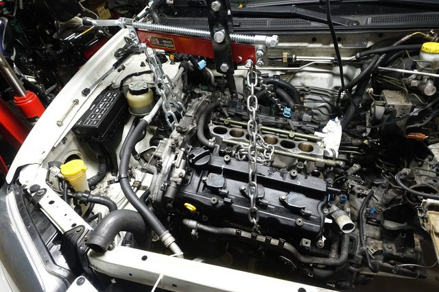
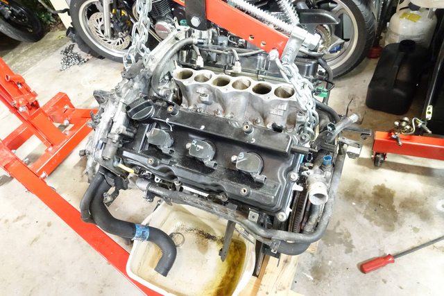
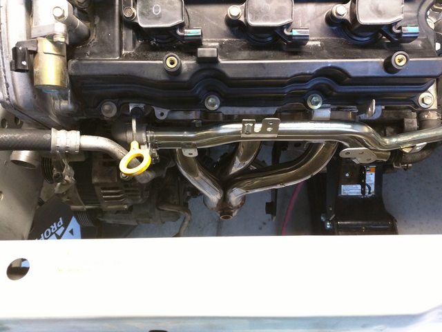
One comment - If this picture is of your "new" engine, I'm seeing one bank of cylinders puking oil and varnish up into the lower intake manifold. Rings are shot. Just like mine. This is what I saw when I pulled my intake to do the plugs. Oil up in the lower intake runners of the front (radiator side bank). That's what I'm seeing here. Mine burns oil like it's going out of style.
Amazing write up - This is gonna help a lot of people. It has already helped me.
One comment - If this picture is of your "new" engine, I'm seeing one bank of cylinders puking oil and varnish up into the lower intake manifold. Rings are shot. Just like mine. This is what I saw when I pulled my intake to do the plugs. Oil up in the lower intake runners of the front (radiator side bank). That's what I'm seeing here. Mine burns oil like it's going out of style.
Oop, just realized i forgot to move a lot of these photos into the appropriate imgur albums so they could be accessed. They should all be there now in full size!
So, this is the new engine here, and yeah, it seems there's a bit of oil coming out of those holes. I can't see how the rings would be shot on that bank since this is a newer 2005 engine with EGR instead of valve overlap, and it only had 55k on it, but yeah, the front bank does seem to be burning a little more than the rear.
I suppose only time will tell how much oil this thing's consuming, but the intake manifold had a fair amount of gunk in it as well so I was chalking it up to those ports getting the bulk of the mess, but we'll see how bad things get I suppose. I topped it off with about a quart after the initial fill, but after the rebuild I only gave it the recommended capacity, so it needed a bit more. I'll keep track of how much oil it's using and see if that's an issue.
Thanks for the praise! I'm really glad to have helped people out, that's the only reason I did all this, from seeing so many people swapping stuff around, i wanted to give back a little since this is my go-to place for info!
Thanks for the praise! I'm really glad to have helped people out, that's the only reason I did all this, from seeing so many people swapping stuff around, i wanted to give back a little since this is my go-to place for info!
You spent a ton of time on that write up - let alone the actual mechanical work ... The praise is deserved.
How's it running anyway? More power? Any pinging? Is it pretty quiet?
You spent a ton of time on that write up - let alone the actual mechanical work ... The praise is deserved.
How's it running anyway? More power? Any pinging? Is it pretty quiet?
It's running superbly. I can't compare it much to the original engine because it was running so poorly before I replaced it, but it feels very powerful, chirps the tires through second, and is a blast to drive.
I haven't noticed any odd noises aside from an issue i'm having with the driver's side CV axle. After doing the idle adjustment, it dropped right down to 600RPM and stays there quietly. There's a loud hiss when I get on it, but I think that's some intake noise from the NVIS. Haven't heard any odd noises from the engine, it runs quiet and smooth, vibrates a bit at idle. Took it on a 900-mile round trip drive last weekend, ran fine the whole time.
 05-09-2016, 07:19 PM


 The praise is deserved.