
Illustrated timing chain replacement


Thread Starter
Junior Member
Joined: Apr 2016
Posts: 38
Illustrated timing chain replacement
I'm sure there's a ton of threads here on this, and I've seen youtube videos, pictures here and there, and lots of other tidbits of info scattered about, but I just wanted to add one more to the list. Feel free to ignore this thread if it's useless, but I'm hoping it will help someone!
If I'm giving bad info here, someone let me know!
All images can be seen in GIANT size at the imgur album here
Overall, this isn't a hard job, just tedious. I'm doing it with the engine out of the engine as I'm swapping it into a 5.5 Gen, so the upper oil pan is already removed and I'll be going from there.
Most stuff I've seen in my travels says to replace all three chains, the main tensioner, the top guide, the slack guide, and the two small guides in the camshaft chains. Might as well replace the water pump while you're in here, too!
I went to my local Nissan dealer and asked them for the parts needed to do this job, and this is what they sold me. They assured me that this is what their technicians replace when they do a 6th gen timing chain job:
I'm not sure why they don't replace the IVT rings, maybe I can purchase those as well, I'll add them to the list!
Let's get started!
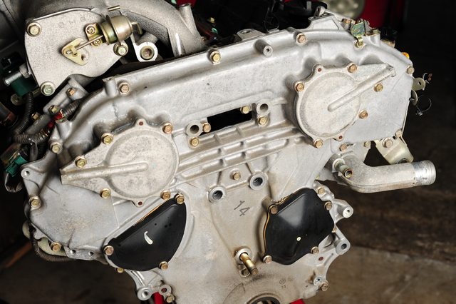
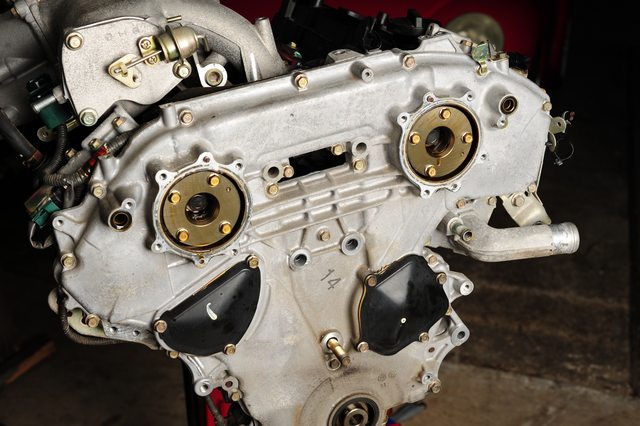
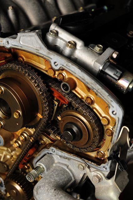
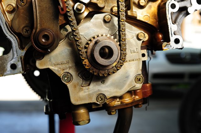
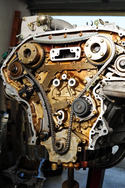
Quick overview of where we're at here: Front of a 2005 Maxima VQ with 55k miles, this was an AT but that doesn't matter since the oil pan is already removed. I'm doing this while I've got it out of the car so I don't have to do it again for a long while.
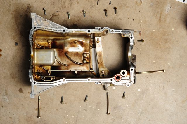
You don't have to remove the upper oil pan to pull the timing cover, but you DO have to unfasten the two bolts that attach it to the cover. If you don't, you'll split your cover when trying to pry it free. This means you must remove the lower oil pan to get to those two bolts. They are the two shown on the right of the image above, the very long one, and the short one.
You'll also need to have the engine mount bracket removed, in the above picture it's already taken off.
The problem with the service manual is that it specifies removing everything, including the rear timing cover, so it has you remove a lot of things that are unnecessary, like the valve covers and variable valve timing solenoids. I didn't remove them to do mine, but you can if you'd like. Just need to get more gaskets and o-rings.
You'll need to remove the crankshaft bolt if you haven't already, it's a bear to pull off since it's torqued to 36ft-lbs, then rotated another 90�. Plus it's been there awhile. It took a friend and I to hold the flex plate and run a large breaker bar on it in order to get it loose.
The manual has you remove the IVT covers, which you have to do because they have o-rings and seals inside them. However, you can leave the black water pump and main tensioner covers attached, no reason to remove them since you are removing the entire timing cover.
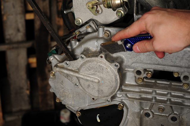
The IVT covers need to be pried off as they're RTV'd on as well as held in place with o-rings, so I used a large prybar to gently pull one side away enough to slip a large screwdriver in, then wiggled the cover back and forth while gently pushing the screwdriver in further to help pull the cover off straight. At the same time I was cutting around the outside of the cover to help remove RTV, since you're mainly wanting to be working against the o-rings, not the RTV.
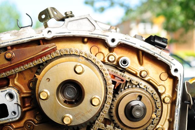
Now that the covers have been removed, the large sprockets are exposed. The main cover can now be removed.
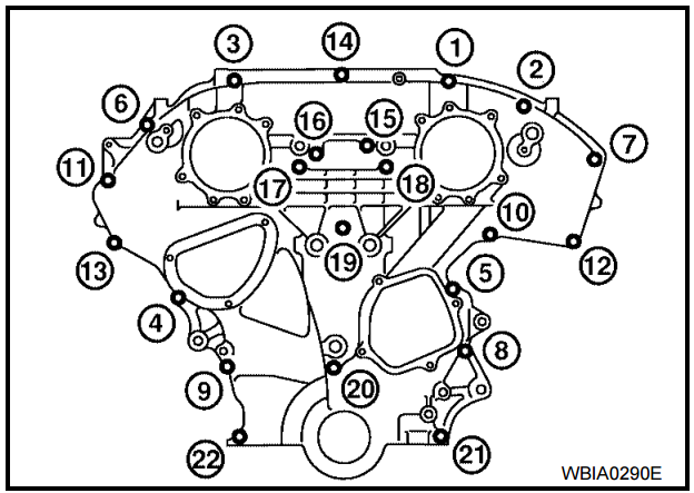
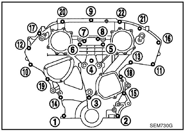
The FSM shows you the proper order in which to remove the bolts so the cover is de-torqued correctly. This may or may not matter, but I followed the guide.
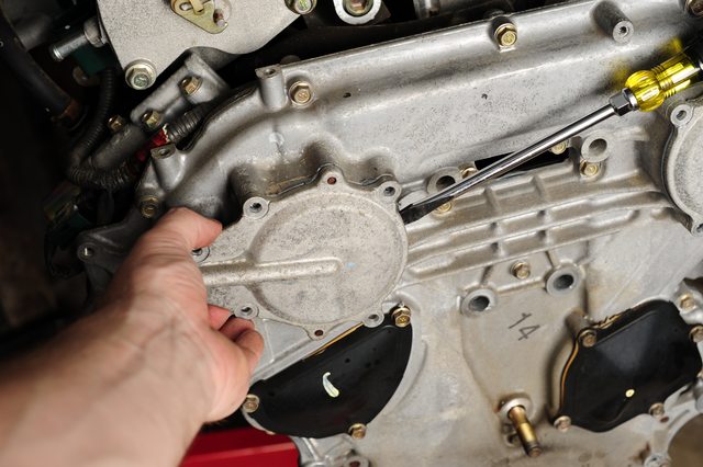
Once all the bolts have been removed, it's time to pull the case. There are two slots at the top of the case, denoted in the FSM as spots to pry at. These work well for the top, but getting down to the side, it's more difficult.
I found a third location to pry at, which seems to work well, and is far enough back from the mating surfaces that it shouldn't cause marring if you use a screwdriver:
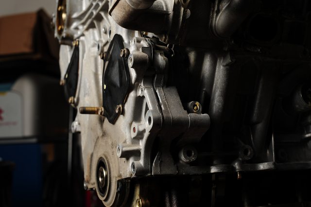
The location just above the bolt hole nearest the camera in the photo is a slot that is exposed even when the cases are stuck together, and should help get them pried apart. Remember to pull it off evenly, and use a knife to cut around the outside should you need to, which may help with the initial prying near the top.
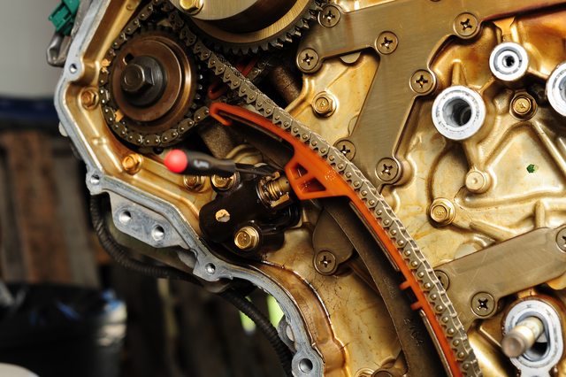
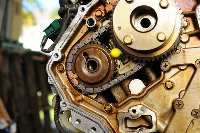
Once that's off, you've got the exposed timing chain area!
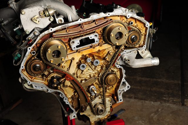
Here's the main problem, the 'slack guide' as Nissan calls it. This part seems to have been engineered with plastic that is too brittle, and too thin near the top, causing it to break off and drop down after some time in the oil.
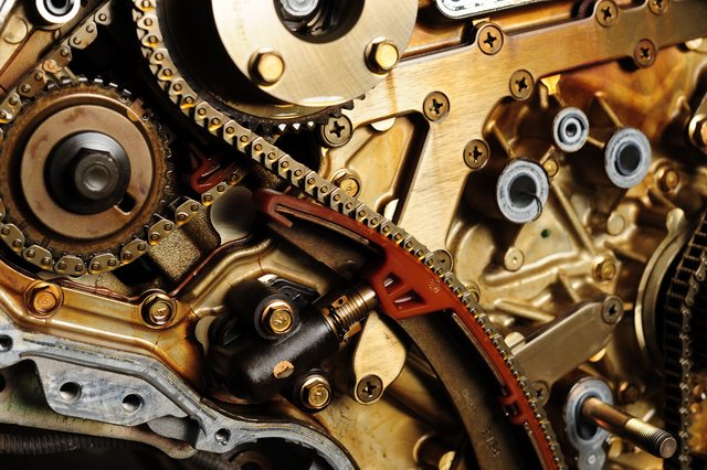
The part has since been superceded by a newer part, which seems to be made from a different material, as well as having a beefier upper corner.. You can see on the old one where the plastic is already bending away from the metal, this probably would have broken some number of miles down the road.
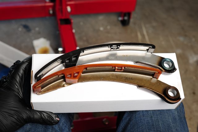
And here is one of the other tensioner guides you should replace, which may or may not also have worn considerably depending on mileage.
Next post: Digging in and replacing the guides.
If I'm giving bad info here, someone let me know!
All images can be seen in GIANT size at the imgur album here
Overall, this isn't a hard job, just tedious. I'm doing it with the engine out of the engine as I'm swapping it into a 5.5 Gen, so the upper oil pan is already removed and I'll be going from there.
Most stuff I've seen in my travels says to replace all three chains, the main tensioner, the top guide, the slack guide, and the two small guides in the camshaft chains. Might as well replace the water pump while you're in here, too!
I went to my local Nissan dealer and asked them for the parts needed to do this job, and this is what they sold me. They assured me that this is what their technicians replace when they do a 6th gen timing chain job:
- 13028-ZK01C - CHAIN-CAMSHAFT - Small camshaft chain - Qty 2
- 13028-ZS70A - CHAIN-CAMSHAFT - Large Crankshaft Chain - Qty 1
- 13070-7Y000 - TENSIONER ASSY-CHAIN - Main tensioner - Qty 1
- 13085-7Y000 - GUIDE-CHAIN,TENSION SIDE - Top Chain Guide - Qty 1
- 13085-7Y010 - GUIDE-CHAIN,TENSION SIDE - Right(fixed) chain guide - Qty 1
- 13091-ZK00A - CHAIN GUIDE - Slack guide (left) - Qty 1
- 13097-ZK01C - TENSIONER FACE - Small tensioner shoe - Qty 2
- 13510-7Y000 - SEAL-OIL,CRANKSHAFT FRONT - Front seal installed in front timing cover - Qty 1
- 15066-ZL80A - SEAL O RING - Small o-rings in studs near top left and right of timing cover - Qty 2
I'm not sure why they don't replace the IVT rings, maybe I can purchase those as well, I'll add them to the list!
Let's get started!
Quick overview of where we're at here: Front of a 2005 Maxima VQ with 55k miles, this was an AT but that doesn't matter since the oil pan is already removed. I'm doing this while I've got it out of the car so I don't have to do it again for a long while.
You don't have to remove the upper oil pan to pull the timing cover, but you DO have to unfasten the two bolts that attach it to the cover. If you don't, you'll split your cover when trying to pry it free. This means you must remove the lower oil pan to get to those two bolts. They are the two shown on the right of the image above, the very long one, and the short one.
You'll also need to have the engine mount bracket removed, in the above picture it's already taken off.
The problem with the service manual is that it specifies removing everything, including the rear timing cover, so it has you remove a lot of things that are unnecessary, like the valve covers and variable valve timing solenoids. I didn't remove them to do mine, but you can if you'd like. Just need to get more gaskets and o-rings.
You'll need to remove the crankshaft bolt if you haven't already, it's a bear to pull off since it's torqued to 36ft-lbs, then rotated another 90�. Plus it's been there awhile. It took a friend and I to hold the flex plate and run a large breaker bar on it in order to get it loose.
The manual has you remove the IVT covers, which you have to do because they have o-rings and seals inside them. However, you can leave the black water pump and main tensioner covers attached, no reason to remove them since you are removing the entire timing cover.
The IVT covers need to be pried off as they're RTV'd on as well as held in place with o-rings, so I used a large prybar to gently pull one side away enough to slip a large screwdriver in, then wiggled the cover back and forth while gently pushing the screwdriver in further to help pull the cover off straight. At the same time I was cutting around the outside of the cover to help remove RTV, since you're mainly wanting to be working against the o-rings, not the RTV.
Now that the covers have been removed, the large sprockets are exposed. The main cover can now be removed.
The FSM shows you the proper order in which to remove the bolts so the cover is de-torqued correctly. This may or may not matter, but I followed the guide.
Once all the bolts have been removed, it's time to pull the case. There are two slots at the top of the case, denoted in the FSM as spots to pry at. These work well for the top, but getting down to the side, it's more difficult.
I found a third location to pry at, which seems to work well, and is far enough back from the mating surfaces that it shouldn't cause marring if you use a screwdriver:
The location just above the bolt hole nearest the camera in the photo is a slot that is exposed even when the cases are stuck together, and should help get them pried apart. Remember to pull it off evenly, and use a knife to cut around the outside should you need to, which may help with the initial prying near the top.
Once that's off, you've got the exposed timing chain area!
Here's the main problem, the 'slack guide' as Nissan calls it. This part seems to have been engineered with plastic that is too brittle, and too thin near the top, causing it to break off and drop down after some time in the oil.
The part has since been superceded by a newer part, which seems to be made from a different material, as well as having a beefier upper corner.. You can see on the old one where the plastic is already bending away from the metal, this probably would have broken some number of miles down the road.
And here is one of the other tensioner guides you should replace, which may or may not also have worn considerably depending on mileage.
Next post: Digging in and replacing the guides.
Last edited by Chorca; May 11, 2016 at 01:21 AM.
Thread Starter
Junior Member
Joined: Apr 2016
Posts: 38
Replacing the guides...
Now that the cover is off and everything is exposed, we can see the chains and the sprockets. Now TDC has to be set on the engine, and an easy way to do that is shown in a few youtube videos as well as here.
Here, I would recommend that you take the time to loosen or break free (NOT REMOVE) the bolts on the four camshafts. These things are torqued to around 76 ft-lbs and have been in there for awhile. It took my 1/2" impact a few good hits to get them moving, and better to do it now while you're under tension on an old chain and everything is timed, than to try and do it individually. If you're removing the valve cover you can ignore and just throw a wrench on the camshaft flats to hold it in place (according to the FSM).
Reinstall the crank drive pulley, or use a large nut as a spacer for the crankshaft, so you don't bottom out the bolt in the bore when using it to turn the crank. Screw the crank bolt back on and use a breaker bar or large ratchet to turn the 19mm bolt clockwise, until the notches on the large sprockets (intake), and the keyways on the small sprockets (exhaust) are all pointing 'up', with respect to the angle of the block on each side.
The small dot punched in the large pulley and the keyway in the small one are both pointing in the same direction. This should be the same for the other side of the engine. The keyway in the crankshaft should be pointing at around 11 o'clock position.
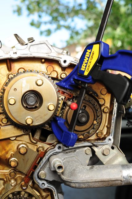
With TDC set, tension can be relieved from the chain. The main tensioner has a small hole in it, and the piston itself has a deep groove near the end of the piston. The piston must be compressed down into the bore enough for the slot to line up with the hole, at which point a 'suitable tool' can be inserted. In this case I'm using a small allen wrench, which worked well throughout the repair.
Important!: The small black clip barely visible behind the slot must be squeezed while the tensioner is being compressed. It prevents the tensioner from collapsing back into the bore should the spring or something else fail internally. Squeezing it releases the clamp and allows you to push the tensioner back.
You should be able to compress this by hand since the guide gives you a slight mechanical advantage.
With the tension removed, the tensioner can now be unbolted from the plate and set aside. If you plan to reuse the tensioner, make sure the pin stays in the hole, or the piston may fire out of the bore and leave you with a borked tensioner! If you're replacing it, the new tensioner should come with a pin already installed in the hole. Leave it in place until you're completely done with the chain installation.
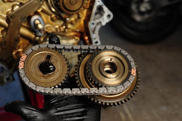
New (left) old (right):
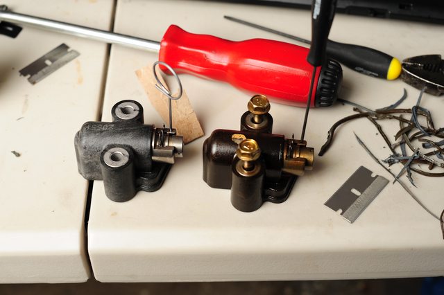
With the tensioner removed, the chain is now slacked and you can remove the top chain guide (above the camshaft sprockets), slack guide and the chain from the sprockets and water pump. The right guide can also be removed and replaced if desired now.
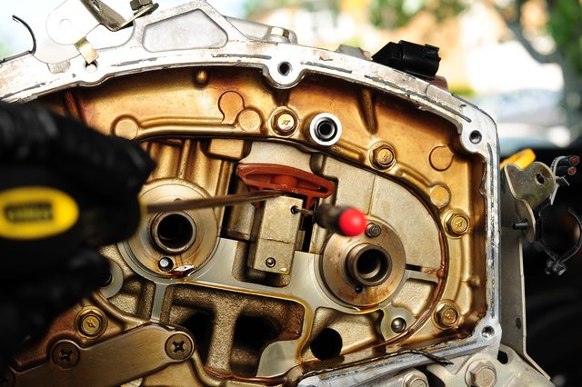
Next, the small tensioners have to be compressed.
I used a small squeeze clamp to do the job, which worked very well, and since you can't put a ton of torque into them, which prevented me from breaking something like a screw clamp might. I clamped between the chain and the back of the tensioner, then inserted a small tool into the hole. It didn't go as deep in these as the main tensioner, but still held. I then released the clamp and made sure the tensioner stayed compressed. Make sure not to bump the tool while you're working!
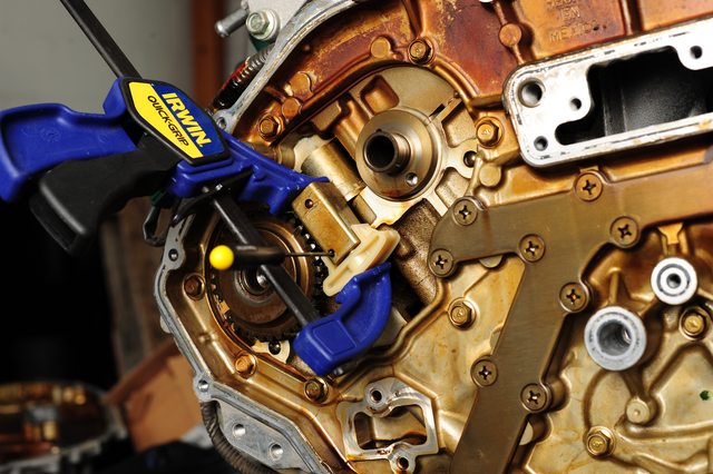
Next it's time to remove the camshaft sprockets and chain.
Remove the bolts holding the camshaft sprockets in place, and make sure you note they are different sizes, the longer one goes into the larger sprocket.
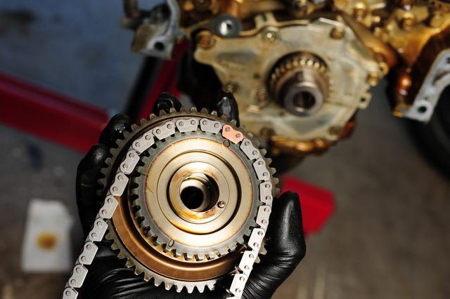
The chain should come off along with the two sprockets. Make sure to note their orientation. The right and left banks are using different markings; facing the timing cover, the left bank uses dots, and the right bank uses slots.
Although you may be able to get the chain off without removing the exhaust (small) sprocket, depending on the wear of the tensioner, it will have to come off in order to get the new chain on.
With the sprockets and chain removed from one side at a time (so you don't get them mixed up!) The guide can now be removed. This is quite difficult, it's a snap-fit and it really didn't want to let go. I ended up using a screwdriver to pry the guide off while pushing inwards on my makeshift pin to make sure it didn't pop out, and finally got it free.
I used the same technique I used to compress the tensioner to install the new guide. It's pretty tough to get them on, so the clamp helped a lot. I made sure to hold that pin in place while doing it to both keep the plunger from popping out, but also from sliding all the way in instead of clicking into the guide.
Repeat for the other side, and then we can reinstall the camshaft sprockets and chains.
Here, I would recommend that you take the time to loosen or break free (NOT REMOVE) the bolts on the four camshafts. These things are torqued to around 76 ft-lbs and have been in there for awhile. It took my 1/2" impact a few good hits to get them moving, and better to do it now while you're under tension on an old chain and everything is timed, than to try and do it individually. If you're removing the valve cover you can ignore and just throw a wrench on the camshaft flats to hold it in place (according to the FSM).
Reinstall the crank drive pulley, or use a large nut as a spacer for the crankshaft, so you don't bottom out the bolt in the bore when using it to turn the crank. Screw the crank bolt back on and use a breaker bar or large ratchet to turn the 19mm bolt clockwise, until the notches on the large sprockets (intake), and the keyways on the small sprockets (exhaust) are all pointing 'up', with respect to the angle of the block on each side.
The small dot punched in the large pulley and the keyway in the small one are both pointing in the same direction. This should be the same for the other side of the engine. The keyway in the crankshaft should be pointing at around 11 o'clock position.
With TDC set, tension can be relieved from the chain. The main tensioner has a small hole in it, and the piston itself has a deep groove near the end of the piston. The piston must be compressed down into the bore enough for the slot to line up with the hole, at which point a 'suitable tool' can be inserted. In this case I'm using a small allen wrench, which worked well throughout the repair.
Important!: The small black clip barely visible behind the slot must be squeezed while the tensioner is being compressed. It prevents the tensioner from collapsing back into the bore should the spring or something else fail internally. Squeezing it releases the clamp and allows you to push the tensioner back.
You should be able to compress this by hand since the guide gives you a slight mechanical advantage.
With the tension removed, the tensioner can now be unbolted from the plate and set aside. If you plan to reuse the tensioner, make sure the pin stays in the hole, or the piston may fire out of the bore and leave you with a borked tensioner! If you're replacing it, the new tensioner should come with a pin already installed in the hole. Leave it in place until you're completely done with the chain installation.
New (left) old (right):
With the tensioner removed, the chain is now slacked and you can remove the top chain guide (above the camshaft sprockets), slack guide and the chain from the sprockets and water pump. The right guide can also be removed and replaced if desired now.
Next, the small tensioners have to be compressed.
I used a small squeeze clamp to do the job, which worked very well, and since you can't put a ton of torque into them, which prevented me from breaking something like a screw clamp might. I clamped between the chain and the back of the tensioner, then inserted a small tool into the hole. It didn't go as deep in these as the main tensioner, but still held. I then released the clamp and made sure the tensioner stayed compressed. Make sure not to bump the tool while you're working!
Next it's time to remove the camshaft sprockets and chain.
Remove the bolts holding the camshaft sprockets in place, and make sure you note they are different sizes, the longer one goes into the larger sprocket.
The chain should come off along with the two sprockets. Make sure to note their orientation. The right and left banks are using different markings; facing the timing cover, the left bank uses dots, and the right bank uses slots.
Although you may be able to get the chain off without removing the exhaust (small) sprocket, depending on the wear of the tensioner, it will have to come off in order to get the new chain on.
With the sprockets and chain removed from one side at a time (so you don't get them mixed up!) The guide can now be removed. This is quite difficult, it's a snap-fit and it really didn't want to let go. I ended up using a screwdriver to pry the guide off while pushing inwards on my makeshift pin to make sure it didn't pop out, and finally got it free.
I used the same technique I used to compress the tensioner to install the new guide. It's pretty tough to get them on, so the clamp helped a lot. I made sure to hold that pin in place while doing it to both keep the plunger from popping out, but also from sliding all the way in instead of clicking into the guide.
Repeat for the other side, and then we can reinstall the camshaft sprockets and chains.
Last edited by Chorca; May 9, 2016 at 10:14 PM.
Thread Starter
Junior Member
Joined: Apr 2016
Posts: 38
Installation is the reverse of disassembly...
Now that the guides for the camshaft tensioners have been installed, the chains and sprockets can be installed.
(Quick note here though, this is a good time to get in there and scrape off all that RTV from the face of the timing cover, as the chains aren't here to get in your way, or get all dirty from flecks of RTV falling into them! I took this time to clean the face up nice and neat.)
First, the new chain should have 3 colored links.. Two right next to each other, and one opposite them.
The single link goes to the dot or slot (depending on left or right bank) on the large sprocket, and the two small go onto the small sprocket's dots or slots.
First, line up the large sprocket, since it's on the backside and won't be visible when installing.
Next, line up the two marks on the front of the small sprocket. Once aligned, you can carefully side them back on, which may take a bit of work with the new, non-worn tensioner and new, slightly-tighter chain.
The old chains' colored links may be hard to see, and may or may not be lined up correctly, due to what position the engine was in. As long as you line up the new chain's links though, that's what counts. Install the same as the other side, ensuring the sprockets are seated completely and the chain is in the center of the tensioner guide.
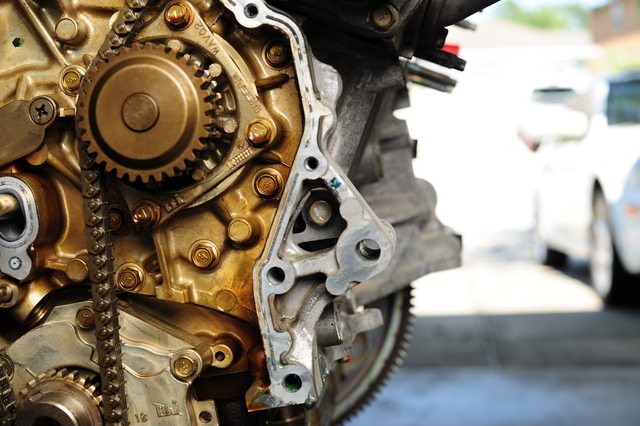
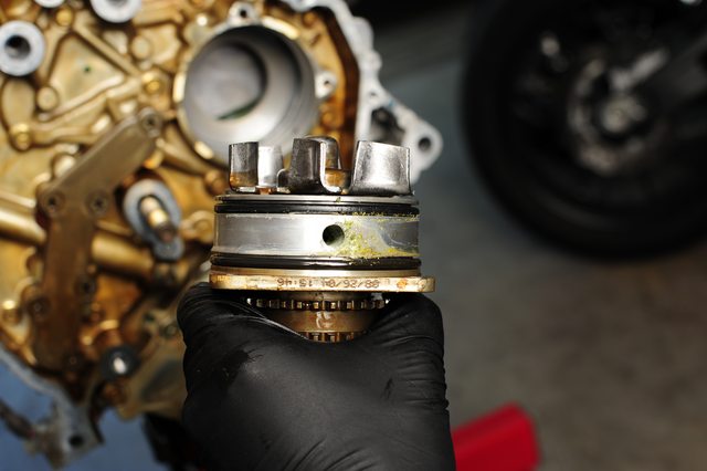
On my engine, I opted to replace the water pump as well, as preventative maintenance even though there was only 55k on it.
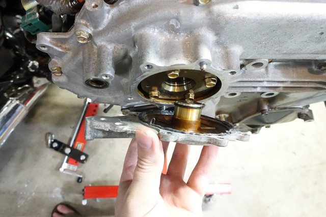
A helpful hint here.. The block still contains coolant in it, even if you've drained the radiator and removed the oil cooler. There's a little drain bolt that lives beside the water pump to help drain the remainder of the coolant from the engine, unscrew it before you do the water pump and you'll prevent a mess!
It's the small bolt in the center of that triangle in the middle of the photo.
I removed the three 10mm bolts holding the water pump in place. I then pried it out using a large prybar on the forward set of sprocket teeth, so my bar would not pry against the water pump housing itself.
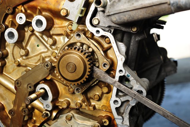
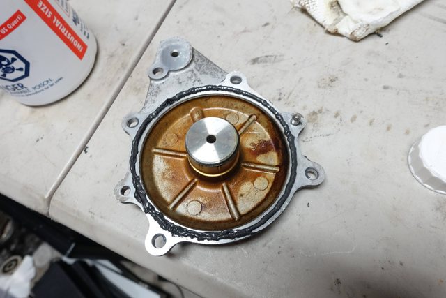
It appears on my pump that the seal was leaking slightly. The area between the two rings is an area connected to a 'weep hole', which allows oil or water that begin to leak past to exit the engine through an opening in the block, rather than contaminate each other. In this instance, it appears coolant has been leaking through one ring, so this was a good thing to replace. The center hole is for coolant or oil leaking through the shaft seal to be able to drain down to the weep hole as well.
With the water pump installed, it's now time to install the large timing chain.
The chain has three colored links, two blue-ish and one copper. The copper link goes to the slot opposite the keyway on the crank sprocket...
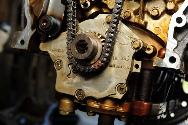
And the blue-ish links each are positioned to the dot on each of the large sprockets.
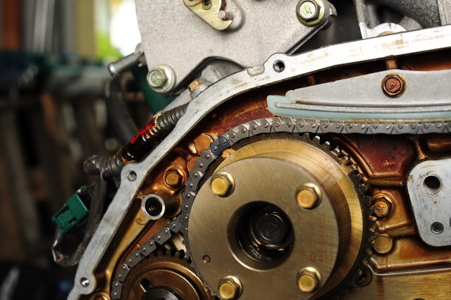
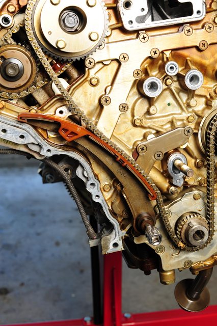
Once the chain is installed and settled properly along all the sprockets, including the water pump, the upper guide can be installed, followed by the slack guide and tensioner.
I found it easiest to install the lower bolt of the tensioner, and swivel it up against the slack guide, as there is still a bit of tension after the upper guide is installed. Pushing firmly on the chain will rotate one of the camshafts to give you a bit more room. Install the bolts and torque to spec.
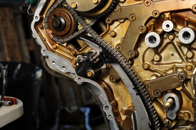
Once the guides are all installed and torqued, and the tensioner ready, the chain correctly set to the timing marks, and everything looks good.. you can then release the tensioner. Pull on the slack guide a bit while pulling the pin, and the tension piston should take up the slack in the system.
It's a good idea to snug up the camshaft gears at this point, reinstall the crankshaft pulley or your spacer, and use the crankshaft bolt to spin the engine slowly. You shouldn't encounter any stiff resistance. If you didn't pull the plugs, there will be some air resistance, but that will lessen as you hold the crankshaft in that position, and you can continue to turn it. If at some point you can't turn it at all, and it feels locked in position, that's bad, and could be valves hitting pistons.. recheck all the timing marks.
This is when I torqued down the camshaft bolts (Don't forget!). They're quite difficult to torque when the engine is out of the car; I had to use a prybar in the flex plate gear to hold the crankshaft steady while torquing them.
Once they're torqued up, you should be good to go. Make sure you torqued all the bolts holding the water pump and chain guides to the specs in the FSM.
Done!
Next up, cleaning and installing the timing cover!
(Quick note here though, this is a good time to get in there and scrape off all that RTV from the face of the timing cover, as the chains aren't here to get in your way, or get all dirty from flecks of RTV falling into them! I took this time to clean the face up nice and neat.)
First, the new chain should have 3 colored links.. Two right next to each other, and one opposite them.
The single link goes to the dot or slot (depending on left or right bank) on the large sprocket, and the two small go onto the small sprocket's dots or slots.
First, line up the large sprocket, since it's on the backside and won't be visible when installing.
Next, line up the two marks on the front of the small sprocket. Once aligned, you can carefully side them back on, which may take a bit of work with the new, non-worn tensioner and new, slightly-tighter chain.
The old chains' colored links may be hard to see, and may or may not be lined up correctly, due to what position the engine was in. As long as you line up the new chain's links though, that's what counts. Install the same as the other side, ensuring the sprockets are seated completely and the chain is in the center of the tensioner guide.
On my engine, I opted to replace the water pump as well, as preventative maintenance even though there was only 55k on it.
A helpful hint here.. The block still contains coolant in it, even if you've drained the radiator and removed the oil cooler. There's a little drain bolt that lives beside the water pump to help drain the remainder of the coolant from the engine, unscrew it before you do the water pump and you'll prevent a mess!
It's the small bolt in the center of that triangle in the middle of the photo.
I removed the three 10mm bolts holding the water pump in place. I then pried it out using a large prybar on the forward set of sprocket teeth, so my bar would not pry against the water pump housing itself.
It appears on my pump that the seal was leaking slightly. The area between the two rings is an area connected to a 'weep hole', which allows oil or water that begin to leak past to exit the engine through an opening in the block, rather than contaminate each other. In this instance, it appears coolant has been leaking through one ring, so this was a good thing to replace. The center hole is for coolant or oil leaking through the shaft seal to be able to drain down to the weep hole as well.
With the water pump installed, it's now time to install the large timing chain.
The chain has three colored links, two blue-ish and one copper. The copper link goes to the slot opposite the keyway on the crank sprocket...
And the blue-ish links each are positioned to the dot on each of the large sprockets.
Once the chain is installed and settled properly along all the sprockets, including the water pump, the upper guide can be installed, followed by the slack guide and tensioner.
I found it easiest to install the lower bolt of the tensioner, and swivel it up against the slack guide, as there is still a bit of tension after the upper guide is installed. Pushing firmly on the chain will rotate one of the camshafts to give you a bit more room. Install the bolts and torque to spec.
Once the guides are all installed and torqued, and the tensioner ready, the chain correctly set to the timing marks, and everything looks good.. you can then release the tensioner. Pull on the slack guide a bit while pulling the pin, and the tension piston should take up the slack in the system.
It's a good idea to snug up the camshaft gears at this point, reinstall the crankshaft pulley or your spacer, and use the crankshaft bolt to spin the engine slowly. You shouldn't encounter any stiff resistance. If you didn't pull the plugs, there will be some air resistance, but that will lessen as you hold the crankshaft in that position, and you can continue to turn it. If at some point you can't turn it at all, and it feels locked in position, that's bad, and could be valves hitting pistons.. recheck all the timing marks.
This is when I torqued down the camshaft bolts (Don't forget!). They're quite difficult to torque when the engine is out of the car; I had to use a prybar in the flex plate gear to hold the crankshaft steady while torquing them.
Once they're torqued up, you should be good to go. Make sure you torqued all the bolts holding the water pump and chain guides to the specs in the FSM.
Done!
Next up, cleaning and installing the timing cover!
Last edited by Chorca; May 9, 2016 at 10:24 PM.

Member
Joined: May 2010
Posts: 128
From: Burlington, Ontario, Canada
Dude - this is a fantastic thread  , as is your one on the engine install. This will come in very handy for myself and many others I'm sure.
Great pictures, perfect write ups ... much appreciated!
How the heck did you find such a low-mile motor? Even the damn timing gear looks new. But yeah - interesting to see the plastic end of the slack guide just starting to bend away from the metal frame. You see it would have let go eventually. I found pieces of mine in oil pan
, as is your one on the engine install. This will come in very handy for myself and many others I'm sure.Great pictures, perfect write ups ... much appreciated!
How the heck did you find such a low-mile motor? Even the damn timing gear looks new. But yeah - interesting to see the plastic end of the slack guide just starting to bend away from the metal frame. You see it would have let go eventually. I found pieces of mine in oil pan
Thread Starter
Junior Member
Joined: Apr 2016
Posts: 38
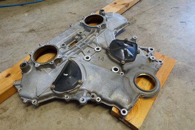
The covers
Alright, apologies for the delay, but I'm finally back working on this thing again!
I had a friend over and he helped me begin the reassembly of the covers themselves. I used a couple razor blades to clean off any of the remaining RTV from the old covers, and used the back of the razor blade to dig into the grooves and clean out the RTV from inside those on the covers.
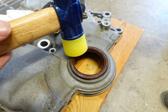
I took the opportunity to set up the cover on a couple of blocks, pry out the old front seal and replace it with a new one.
I used a soft mallet to very slowly and gently tap in the new seal, along with a bit of oil to make sure it slid in nicely. A block of wood would also work, if you don't have a soft hammer.
I wiped all the mating surfaces down with isopropyl alcohol, and used my compressor to blow all of them off to make sure I wasn't leaving any pieces of RTV left on the covers.
Unfortunately, I don't have any photos of putting RTV on the main cover, but it's fairly straight forward. I used Permatex Ultra Black RTV sealant, and deviated from the FSM slightly in the technique.
While the FSM calls for applying the silicone, installing and tightening the cover, the RTV bottle says to apply the bead, install the cover with bolts finger tightened just until it starts to ooze out from the mating surfaces, then let it set up for one hour. After that, complete the torquing process. I can understand why this is, as the RTV will cure a bit before being deformed into the final shape.. It will also provide the pressure against it necessary to prevent any leaks. I used the method printed on the RTV.
Now, you may need to also clean up and install the front oil pan seal at this point as well, if you did not remove the oil pan. Since my upper oil pan is already removed pending a swap, I didn't have to worry about this, but if you did not remove it and only unbolted, then you'll need to reinstall the oil pan seal, and most likely RTV in the spots specified by the FSM, and/or where you saw the RTV originally placed from the factory.
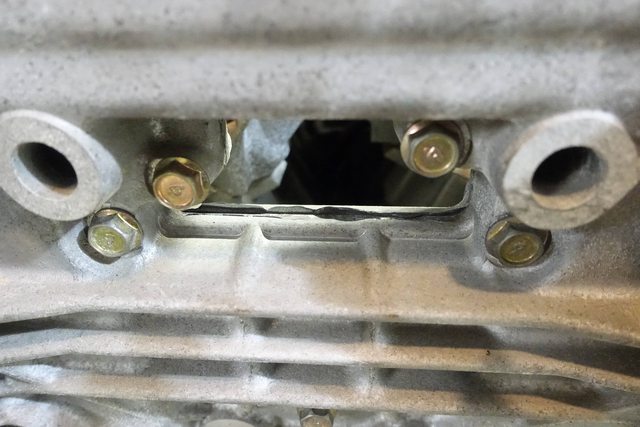
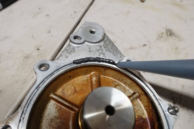
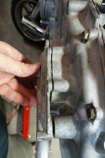
For the initial tightening, this is what I saw at the cracks:
I let it set up for one hour, then torqued all the bolts down to the specified torque, in the specified order:
After taking care of that, I began to RTV the other covers, installing them one by one, cleaning them in the same way as the main cover.
Fully RTV'd main cover
Installing the cover, making sure the dowel pins line up and it's being pushed in straight. I also oiled the plastic seals on the lid that slide into the intake camshafts.
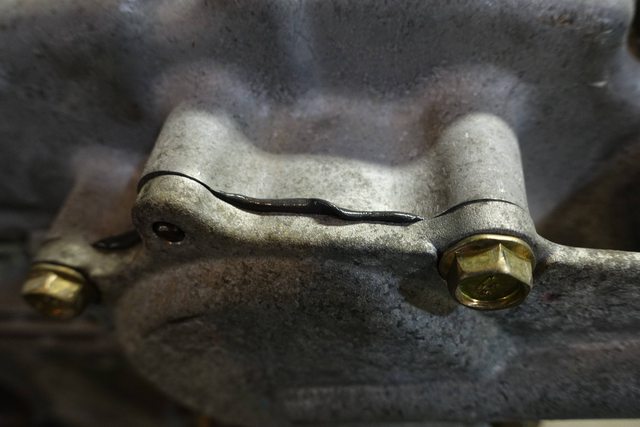
You can see a slight squish as the RTV is compressed.
After gently snugging up the bolts with just fingers on a socket
After waiting another hour, I torqued down the bolts to their spec, in the order the FSM specifies.
I believe that's going to be about it for the write-up here, since the timing chain is complete and I'm going to be going on further with my swap of the engine. You can find that thread over here.
I had a friend over and he helped me begin the reassembly of the covers themselves. I used a couple razor blades to clean off any of the remaining RTV from the old covers, and used the back of the razor blade to dig into the grooves and clean out the RTV from inside those on the covers.
I took the opportunity to set up the cover on a couple of blocks, pry out the old front seal and replace it with a new one.
I used a soft mallet to very slowly and gently tap in the new seal, along with a bit of oil to make sure it slid in nicely. A block of wood would also work, if you don't have a soft hammer.
I wiped all the mating surfaces down with isopropyl alcohol, and used my compressor to blow all of them off to make sure I wasn't leaving any pieces of RTV left on the covers.
Unfortunately, I don't have any photos of putting RTV on the main cover, but it's fairly straight forward. I used Permatex Ultra Black RTV sealant, and deviated from the FSM slightly in the technique.
While the FSM calls for applying the silicone, installing and tightening the cover, the RTV bottle says to apply the bead, install the cover with bolts finger tightened just until it starts to ooze out from the mating surfaces, then let it set up for one hour. After that, complete the torquing process. I can understand why this is, as the RTV will cure a bit before being deformed into the final shape.. It will also provide the pressure against it necessary to prevent any leaks. I used the method printed on the RTV.
Now, you may need to also clean up and install the front oil pan seal at this point as well, if you did not remove the oil pan. Since my upper oil pan is already removed pending a swap, I didn't have to worry about this, but if you did not remove it and only unbolted, then you'll need to reinstall the oil pan seal, and most likely RTV in the spots specified by the FSM, and/or where you saw the RTV originally placed from the factory.
For the initial tightening, this is what I saw at the cracks:
I let it set up for one hour, then torqued all the bolts down to the specified torque, in the specified order:
After taking care of that, I began to RTV the other covers, installing them one by one, cleaning them in the same way as the main cover.
Fully RTV'd main cover
Installing the cover, making sure the dowel pins line up and it's being pushed in straight. I also oiled the plastic seals on the lid that slide into the intake camshafts.
You can see a slight squish as the RTV is compressed.
After gently snugging up the bolts with just fingers on a socket
After waiting another hour, I torqued down the bolts to their spec, in the order the FSM specifies.
I believe that's going to be about it for the write-up here, since the timing chain is complete and I'm going to be going on further with my swap of the engine. You can find that thread over here.

Thread
Thread Starter
Forum
Replies
Last Post
JM AUTO RACING
Group Deals / Sponsors Forum
42
Nov 21, 2017 08:24 AM
6gears
7th Generation Maxima (2009-2015)
2
Feb 21, 2016 10:26 PM
97_GXE
4th Generation Maxima (1995-1999)
18
Feb 17, 2016 04:10 PM