Pre-5spd swap questions
#41
Cool, thanks for the responses. I have the axle carrier bracket, and the metal shim that goes between the engine and tranny (it is a full "o" shape). I don't have the other end of the plug to splice the wires with ease, and I never considered that nor encountered it on the tranny thread I looked at. The tranny mounts are assembled for the most part except for not being attached to the tranny on one side and the frame rail on the other. I won't bother using the mounts laying on the ground since the tranny already has mounts on it.
I am thinking the little black bracket, in the picture with all the nuts and bolts, has something to do with the shift linkage whereby the smaller hole provides a location for the spring, on the end of one of the shift bars, to hold on to.
The person who sent me the clutch pedal said they didn't see anything behind it and nothing came off with it when he removed it. Is this normal, and what kind of space is needed to give the master cylinder rod the right amount of play?
again when you get to that point lemme know, it's easier not to worry about the specifics of it until you are ready for that part of the swap.
#42
The person who sent me the clutch pedal said they didn't see anything behind it and nothing came off with it when he removed it. Is this normal, and what kind of space is needed to give the master cylinder rod the right amount of play?
#43
#44
you will have to connect the 4 wires on the reverse/neutral switch to some other wires inside the engine bay. whenever you get to that point let me know and i'll tell you which ones go to what wire. you can just cut and splice, OR, pop the wires out with a sewing needle and rearrange them within the harness plug (can be a pita tho). speed sensor connector is the same. for the clutch cruise control switch i wired it in series with the one on the brake pedal, and for the clutch start switch i wired it in parallel with the neutral switch on the tranny (send wires thru small hole in firewall, extend to tap into the wiring on the tranny harness)
again when you get to that point lemme know, it's easier not to worry about the specifics of it until you are ready for that part of the swap.
again when you get to that point lemme know, it's easier not to worry about the specifics of it until you are ready for that part of the swap.
Have your methods enabled you to use all of the original features that others have discarded or forgotten about like cruise control and reverse lights?
Thanks for the confirmation on the spring bracket, what might more tension provide?
#45
I am a visual learner, and you have presented some decent diagrams in the past. If you enjoy doing these kinds of things, for future use by others surely, and don't find it to be muc of a bother, I would greatly enjoy try what you have to offer. Either way, I will probably follow your advice.
Have your methods enabled you to use all of the original features that others have discarded or forgotten about like cruise control and reverse lights?
Thanks for the confirmation on the spring bracket, what might more tension provide?
Have your methods enabled you to use all of the original features that others have discarded or forgotten about like cruise control and reverse lights?
Thanks for the confirmation on the spring bracket, what might more tension provide?
the extra tension imo balances the feel of the shifter a bit more. the return spring ONLY returns from the left side... there's a spring atop a checkball inside the tranny that returns the shifter from the right side. So the feel right-of-center is alot different (and heavier) than feel left-of-center, so i bent the bracket to pre-stretch the spring to help even out the feel a little bit.
#47
I have pictures from mine showing what you need to do (though for the starter switch, since I already had the dash out, I went straight into the SMJ rather than running a line through the firewall). I'm trying to upload them to photobucket to post but photobucket isn't working right now
Caped has a little drawing he did floating around here somewhere
Caped has a little drawing he did floating around here somewhere
#48
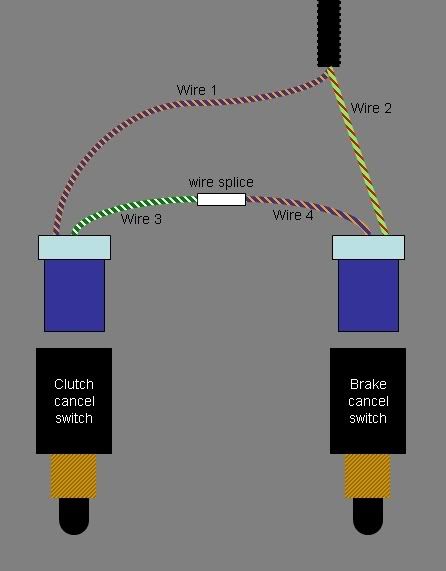
this is how you do the cruise control stuff. wires 1 and 2 are your stock brake-pedal cancel switch wires. using a needle you can slide one of the wires out and swap it with one of the wires on the cruise control harness, and then splice the 2 loose ends together. it doesn't matter what wires go where for this part, it's just a connectivity circuit.

#49
Here you go (these probably won't make sense to you at all until you get in there lol):
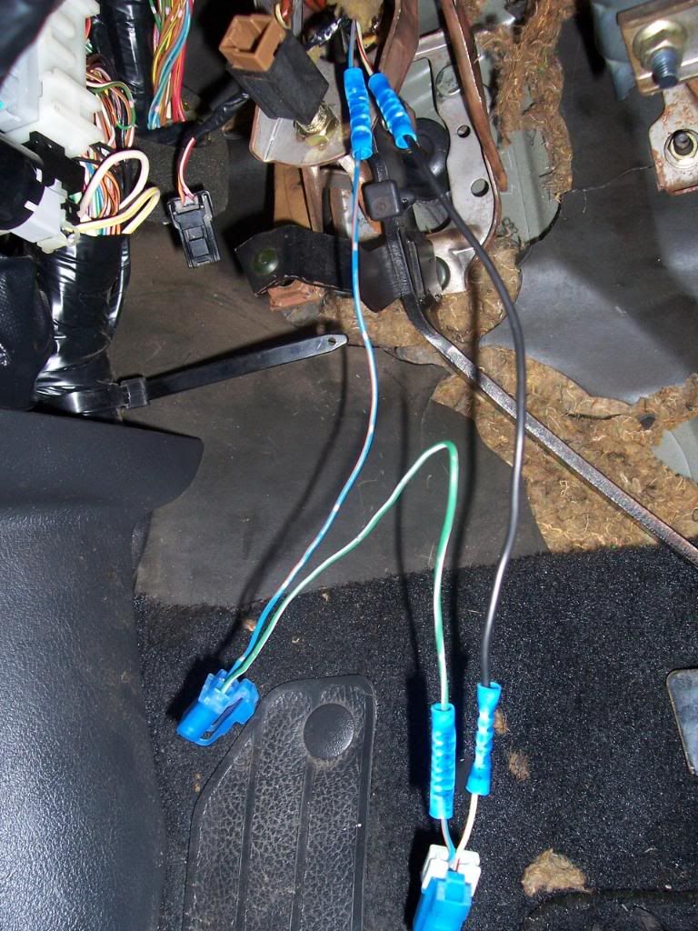
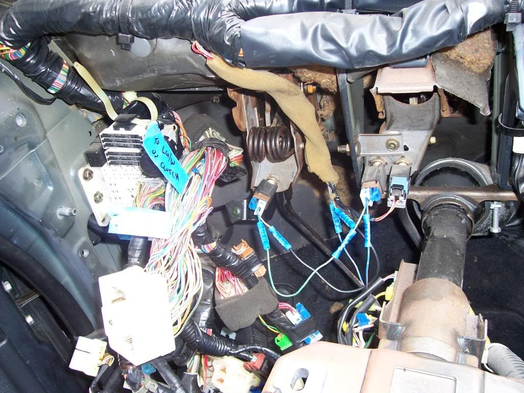
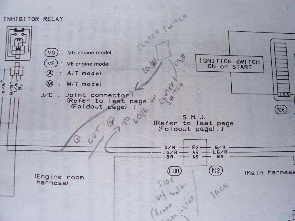
The "clutch switch" as labeled in my crappy handwriting in the pics is the switch on the lower end of the clutch pedal. In the pics above I don't have that switch in yet.


The "clutch switch" as labeled in my crappy handwriting in the pics is the switch on the lower end of the clutch pedal. In the pics above I don't have that switch in yet.
#50
my way is cleaner 
it's just sometimes tricky to get the damn clips to come out from the plug with a needle... but if you can then you only need one wire splice to complete the circuit. (assuming you trim the wrapping around the harness far enough back for the stock wires {1&2} to reach both harnesses)

it's just sometimes tricky to get the damn clips to come out from the plug with a needle... but if you can then you only need one wire splice to complete the circuit. (assuming you trim the wrapping around the harness far enough back for the stock wires {1&2} to reach both harnesses)
#51
#52


#53
It will sink in slowly, I will probably have to draw a large diagram to compensate for all of the nodes in which the wires reach out to. I will use your posts as reference, and submit my diagram to see if it resonates with your information. I will have limited time to do this swap, as far a I know now, and wish to have a solid understanding of what needs to be done prior to the swap. I might be able to get the plugs from the original vehicle, would this make life exponentially easier, or require just as much splicing? I like the thought of a clean look and function, though wire crimps do seem just as professional in my mind.
]Thanks for the pics and diagram, they will make it easier to grasp the necessary steps, for sure!
]Thanks for the pics and diagram, they will make it easier to grasp the necessary steps, for sure!
#55
It will sink in slowly, I will probably have to draw a large diagram to compensate for all of the nodes in which the wires reach out to. I will use your posts as reference, and submit my diagram to see if it resonates with your information. I will have limited time to do this swap, as far a I know now, and wish to have a solid understanding of what needs to be done prior to the swap. I might be able to get the plugs from the original vehicle, would this make life exponentially easier, or require just as much splicing? I like the thought of a clean look and function, though wire crimps do seem just as professional in my mind.
]Thanks for the pics and diagram, they will make it easier to grasp the necessary steps, for sure!
]Thanks for the pics and diagram, they will make it easier to grasp the necessary steps, for sure!
#56

#57
Just an update:
Had the chance to work in a shop with my mechanic friend who was kind enough to help. We got a lot done and we were able to clean up all the parts more so than I expected. Just a few pics for fun.

This was covered in dirt and grease, and this can be seen in the original pics posted.

These were rust bombs before the resurrection my buddy was able to do.

All the misc. parts that were also dirty and grimy, now shiny and ready to be installed, and the funny thing about it is I have more parts than I need for the swap.

My dude working hard on a PS pump replacement whihc proved to be unnecessary as the pump put on didn't work vs. the old one which whined.... He had it done in 45 minutes, impressive to me considering he removed the axle too, which I said wasn't necessary, but thats just how you dare a Master Mechanic: by telling him something isn't worth doing.
Caped: any chance the diagram manifested itself into existence? Just curious, I am in no hurry, and don't expect anything from you or anyone who has said they would contribute. I will be moving into a home with a basement that I can pull Max into so I can safely swap the tranny on a concrete floor vs. my front lawn here.
I can't wait to feel the power of my rebuilt VG with a tranny that doesn't slip around.......... Plus it still feels cool to drive a manual for some reason.
Had the chance to work in a shop with my mechanic friend who was kind enough to help. We got a lot done and we were able to clean up all the parts more so than I expected. Just a few pics for fun.
This was covered in dirt and grease, and this can be seen in the original pics posted.
These were rust bombs before the resurrection my buddy was able to do.
All the misc. parts that were also dirty and grimy, now shiny and ready to be installed, and the funny thing about it is I have more parts than I need for the swap.
My dude working hard on a PS pump replacement whihc proved to be unnecessary as the pump put on didn't work vs. the old one which whined.... He had it done in 45 minutes, impressive to me considering he removed the axle too, which I said wasn't necessary, but thats just how you dare a Master Mechanic: by telling him something isn't worth doing.
Caped: any chance the diagram manifested itself into existence? Just curious, I am in no hurry, and don't expect anything from you or anyone who has said they would contribute. I will be moving into a home with a basement that I can pull Max into so I can safely swap the tranny on a concrete floor vs. my front lawn here.
I can't wait to feel the power of my rebuilt VG with a tranny that doesn't slip around.......... Plus it still feels cool to drive a manual for some reason.
#58
I am curious as I have my shopping cart stacked up on Rockauto.
Do I need the clutch alignment tool to get things 100%?
I guess the input shaft seal is located inside the tranny?
Thanks for all the help, it is greatly appreciated!
Do I need the clutch alignment tool to get things 100%?
I guess the input shaft seal is located inside the tranny?
Thanks for all the help, it is greatly appreciated!
#59
What you will have to do instead, if you leave the a/t pilot bushing in place, is LOOSELY tighten the pressure plate bolts so the clutch disc can easily be moved around, then temporarily mount the tranny and tighten the pressureplate bolts a little bit more so that the clutch is immobilized (through the starter hole... turn the motor over from the crank pulley to gain access to at least 4 of the bolts spaced evenly around the clutch).
Then pull the tranny back off and torque the bolts down per fsm in as much of a star-pattern as you can (there's 9 bolts so if you count off by 4's you will march your way around and hit all 9..... pracitice your star pattern using this random google pic that has nothing to do with maximas
 )
)
#60
I dont' really want to find a pilot bushing for the manual and will save money, not time obviously, by following the latter procedure. Thanks for the advice, I guess I don't need to worry about the input shaft seal seein as I can't see it to change it?
#61
depends... if you can yank the a/t bushing (big fat thing) out and install a m/t pilot bushing, the tool will help. If you can't, then it won't.
What you will have to do instead, if you leave the a/t pilot bushing in place, is LOOSELY tighten the pressure plate bolts so the clutch disc can easily be moved around, then temporarily mount the tranny and tighten the pressureplate bolts a little bit more so that the clutch is immobilized (through the starter hole... turn the motor over from the crank pulley to gain access to at least 4 of the bolts spaced evenly around the clutch).
Then pull the tranny back off and torque the bolts down per fsm in as much of a star-pattern as you can (there's 9 bolts so if you count off by 4's you will march your way around and hit all 9..... pracitice your star pattern using this random google pic that has nothing to do with maximas )
)

What you will have to do instead, if you leave the a/t pilot bushing in place, is LOOSELY tighten the pressure plate bolts so the clutch disc can easily be moved around, then temporarily mount the tranny and tighten the pressureplate bolts a little bit more so that the clutch is immobilized (through the starter hole... turn the motor over from the crank pulley to gain access to at least 4 of the bolts spaced evenly around the clutch).
Then pull the tranny back off and torque the bolts down per fsm in as much of a star-pattern as you can (there's 9 bolts so if you count off by 4's you will march your way around and hit all 9..... pracitice your star pattern using this random google pic that has nothing to do with maximas
 )
)
#62
I think I will forgo any cosmetic surgery on tools with this project. I have grown accustomed to striving and working harder than necessary, when it comes to projects with Max, so this is nothing new!
No one has changed the input shaft seal?
No one has changed the input shaft seal?
#63
I dunno, if your buddy is a master mechanic he should have a pilot bearing puller. If not, they're real cheap at Harbor Freight. I pulled mine out just fine with the cheap Harbor Freight puller.
The m/t "bushing" is literally like a $2 piece. I mean, the hassle of trying to line up the clutch disc through the starter hole really isn't worth the trouble IMO if you can just get the a/t bushing out. Now if you literally CANNOT (for whatever reason) get the a/t bushing out then I understand doing the other method. Nothing wrong with the other method... but I mean, you did say that you want everything clean/stock or whatever.. and using the correct bushing with a clutch alignment tool would be the clean/stock way. Not that it's a big deal, but just saying
The m/t "bushing" is literally like a $2 piece. I mean, the hassle of trying to line up the clutch disc through the starter hole really isn't worth the trouble IMO if you can just get the a/t bushing out. Now if you literally CANNOT (for whatever reason) get the a/t bushing out then I understand doing the other method. Nothing wrong with the other method... but I mean, you did say that you want everything clean/stock or whatever.. and using the correct bushing with a clutch alignment tool would be the clean/stock way. Not that it's a big deal, but just saying

#64
Eh, all this is true, but I am no where near a harbor freight nor have I asked my masterful friend if he would be able to try and get it off, which he most definitely would say he could do. He has helped me alot, and I don't want to tie him down because he won't stop working!
Besides, where is the fun in a clean, easy, and smooth project on a Maxima? I think I saw this as an example of a oxymoron in my dictionary..........
Not to mention I already put in the order from rockauto and I have told myself not to buy any more parts since I can do the swap with what I have. Even though, for $15 more, I could do as you say and have the alignment tool and a m/t bushing, which would save me a little bit of time and a lot of effort. I need the exercise mentally and physically, so I am ready for the obstacle(s).
#65
I hear ya, to each his own. I dunno, if it were me, seeing as I've for unexpected reasons had to drop my transmission several times in between clutch jobs, I just think I'd get sick of trying to line it up without the clutch tool. I think I'd be kicking myself each time I had to re-align it that I just didn't put in the m/t bushing and use the alignment tool from day one.
Nonetheless, Caped and other guys here have had no issues, and I'm sure they have the 'system' down good where it's not a problem for them, so I'm sure you'll have no issues
Nonetheless, Caped and other guys here have had no issues, and I'm sure they have the 'system' down good where it's not a problem for them, so I'm sure you'll have no issues
#66
how did you get the tool to work with the a/t bushing installed? i suppose if you carefully and evenly wrap the tip of the tool with tape that will take up the slack... cuz the a/t bushing's hole is a tiny bit bigger than the m/t bushing's hole. On my Z i absolutely MUST remove the thing cuz the pilot bushing is in constant use but for the maxima it's just for alignment.
You could probably drill and tap holes into the a/t bushing also and run some bolts into it to make it easier to have something to grab onto
You could probably drill and tap holes into the a/t bushing also and run some bolts into it to make it easier to have something to grab onto

#67
Just an update:
Everything is awaiting the proper time to swap. It would have happened the other weekend when I got some help and cleaned all the parts up (pics above), but I wasn't ready nor would we have had time.
Now, I was going to deal with the clutch alignment the hard way, but my mechanic who will be helping me with the swap insists that I go ahead and buy the alignment tool with the m/t bushing, unless "I enjoy ripping my pubic hair out". Mechanics have such a way with words, especially in Alabama, but that's besides the point.
I went ahead and painted the rusty brackets and calipers:


#68
just so you know, that mount with the big L-shaped bracket and 3 "no smoking signs" is gonna have to be separated for installation most likely. the way i always did it was to leave the L-shape bracket on as a handle, and to leave the rubber mount attached to the frame bracket, and just slide the 2 studs through the holes and tighten the nuts to finish off that mount. so i hope you didn't leave them together painted or else you might experience peeling.
#69
Just curious to see if you guys can enlighten me once more on the subject of pilot bushings n such. In the pic, obviously part # 12330 is the a/t pilot bushing, but there is no m/t bushing very apparent, to me atleast. The part # 3202 is labeled as crankshaft bushing, and is the same for the SOHC engine, which is what I have, but the tranny came from the DOHC VE, so whats the word?


#70
Just curious to see if you guys can enlighten me once more on the subject of pilot bushings n such. In the pic, obviously part # 12330 is the a/t pilot bushing, but there is no m/t bushing very apparent, to me atleast. The part # 3202 is labeled as crankshaft bushing, and is the same for the SOHC engine, which is what I have, but the tranny came from the DOHC VE, so whats the word?


#71
Cool, thanks for the confirmation, and I will put in the order since it seems more plausible to try and utilize the alignment tool. Thanks for the heads up on the tranny mount and "L" shaped bracket. Had any chance to design a diagram for the wire up? No pressure, I think I will try and make one from the info available from this thread and your discussion thread and then post it to see if it's correct.
#72
Cool, thanks for the confirmation, and I will put in the order since it seems more plausible to try and utilize the alignment tool. Thanks for the heads up on the tranny mount and "L" shaped bracket. Had any chance to design a diagram for the wire up? No pressure, I think I will try and make one from the info available from this thread and your discussion thread and then post it to see if it's correct.
#73
back up lights are b/c ppl never rewire the old a/t's inhibitor switch thingy... it's super easy actually, as long as you have something to pop the little spade connnectors out of the harness plugs. you just have to re-arrange the a/t's wires to correspond with the m/t's wires. so my car (and nc90gxe's car, which i swapped in march) starts in neutral w/ clutch up, starts in-gear WITH clutch down, reverse lights work, and cruise works. also the cruise will work fine if you never add the clutch cancel switch. i always cancel cruise with the clutch switch actually, because of the way my pedal is set up (no return spring).
here's an example of what i meant with the R/N switch wiring
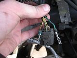
swap the wires around till you end up with this, EXCEPT you need red/black, NOT yellow/black (the original mistake was due to a misprint in the FSM)
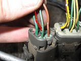


here's an example of what i meant with the R/N switch wiring

swap the wires around till you end up with this, EXCEPT you need red/black, NOT yellow/black (the original mistake was due to a misprint in the FSM)


When looking at this and the brake cancel switch/clutch cancel switch diagram you posted previously, I think I have an okay understanding of what to do. Except for two minor questions (#3 and #4).
- rearrange the harness of the m/t to look like the second pic
- so that it matches up with the a/t plug in form and function
- extract one wire from the brake cancel switch plug and place it into the clutch cancel switch
- then link the two connections left open with a wire, or two as shown in the pic
- the wires extracted from the harness in the first pic (the a/t inhibitor switch) are the same G and Y/B wires in the second?
- I am guessing the sensing device that detects the N/R position is inside the m/t?
- I am guessing the clutch cancel switch is the one closer to the firewall, but this would leave the one that is engaged with the clutch "UP" out of the loop, unless I wired it like you did Caped, correct?
- I am interested if your setup provides a more reasonable clutch function; does this setup disturb any components like the TOB or either cylinders b/c of the small amount of pressure present; or do you think it balances out naturally without the spring (is there no pressure)?
I hope my description isn't too far off and my questions don't involve too much misinformation, if any, but I know I can't be too far from the truth.
#74
So Caped (and you other swappers),
When looking at this and the brake cancel switch/clutch cancel switch diagram you posted previously, I think I have an okay understanding of what to do. Except for two minor questions (#3 and #4).
I hope my description isn't too far off and my questions don't involve too much misinformation, if any, but I know I can't be too far from the truth.
When looking at this and the brake cancel switch/clutch cancel switch diagram you posted previously, I think I have an okay understanding of what to do. Except for two minor questions (#3 and #4).
- rearrange the harness of the m/t to look like the second pic
- so that it matches up with the a/t plug in form and function
- extract one wire from the brake cancel switch plug and place it into the clutch cancel switch
- then link the two connections left open with a wire, or two as shown in the pic
- the wires extracted from the harness in the first pic (the a/t inhibitor switch) are the same G and Y/B wires in the second?
- I am guessing the sensing device that detects the N/R position is inside the m/t?
- I am guessing the clutch cancel switch is the one closer to the firewall, but this would leave the one that is engaged with the clutch "UP" out of the loop, unless I wired it like you did Caped, correct?
- I am interested if your setup provides a more reasonable clutch function; does this setup disturb any components like the TOB or either cylinders b/c of the small amount of pressure present; or do you think it balances out naturally without the spring (is there no pressure)?
I hope my description isn't too far off and my questions don't involve too much misinformation, if any, but I know I can't be too far from the truth.
i never got around to taking a pic that shows the right way to do it. I'll take one next time i am next to my car.
#75
Well, I hope no one followed the instructions I quoted from the other swap discussion, but I guess they would have figured it out eventually! How did the car react with the wires in this setup? Just curious if it worked, at all.............

#77
Finally got around to sanding the clutch surfaces off a bit, just curious to see if they are something to worry about:


Any chance I could get the correct colors and their arrangement?


Any chance I could get the correct colors and their arrangement?

#80
personally i would not use that clutch pp or flywheel... they look kinda gnarly. that and one of them (looks like the pp) has micro-cracks on it
downloading the a/t and m/t fsm's now... i'll print it out and look at the wiring again to make sure i don't mislead you with my oops-that-was-wrong picture.
lol @
downloading the a/t and m/t fsm's now... i'll print it out and look at the wiring again to make sure i don't mislead you with my oops-that-was-wrong picture.
lol @


 you're right.. it's the return spring bracket. i bent mine actually, to make the return a bit firmer.


