Turbo VG swapped stanza

 01-25-2018, 01:12 PM
#282
Member
Thread Starter

Join Date: Oct 2016
Posts: 284
i got the car pretty much 100% road ready, still burning off oil from the exhaust before i take it out of the garage but all of the gauges and everything is working now so i can get the car all the way warmed up and stuff and keep an eye on it and know if its going to be safe etc.
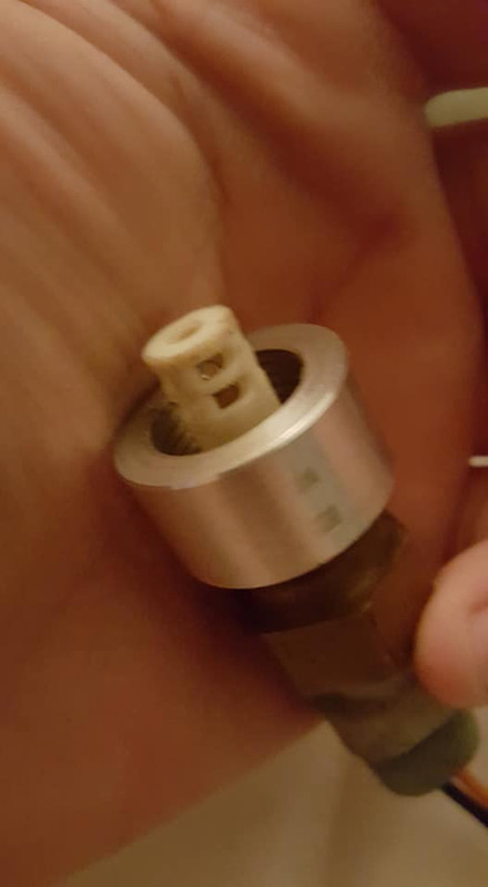
the lase gauge i have to sort out is the speedometer. ive been trying to source a speed sensor for a while now but i had this one from the auto trans i got off of that maxima a while ago but it didnt fit into the other trans, the diameter of the holes are slightly different so the first thing i did was put it in my lathe to turn it down. i knew i couldnt use this speed sensor without modifying it further anyway i just wanted to plug up the hole in my trans with it in the mean time if i decide to drive the car.

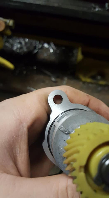

so after i did this i tested the fit and it does physically fit into the hole now but the oring is a little too tight for it to go all the way in so i need to relieve the oring more if its going to be a plug but next thing i wanted to see was how it worked and if i could use the electronic internals of this speed sensor and mate them to a mechanical speed sensor to have a working speed sensor for the stanza since a mechanical speed sensor is easier to get than the proper electric one. back to the lathe it went...

after i cut the groove all i had to do was twist a screwdriver in there and the top popped right off.
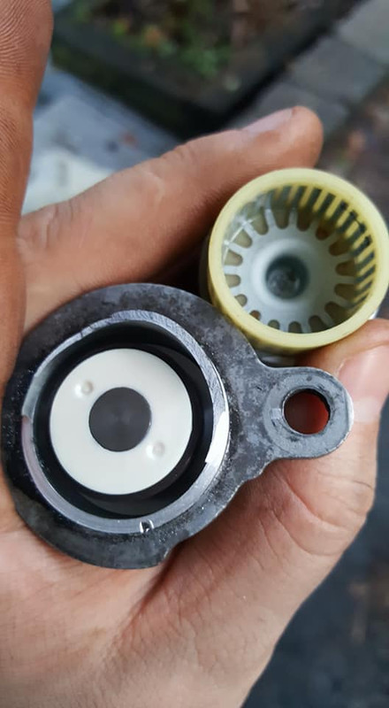
and here are all the major components of the speed sensor. its a pretty simple part, it appears to me to essentially just be a tiny generator, a permanent magnet spins inside of a cage that generates a voltage which is sent directly to the speedometer, so the faster it spins, the higher the voltage the higher the speedo reads. so the speedo is basically the same as a voltmeter.
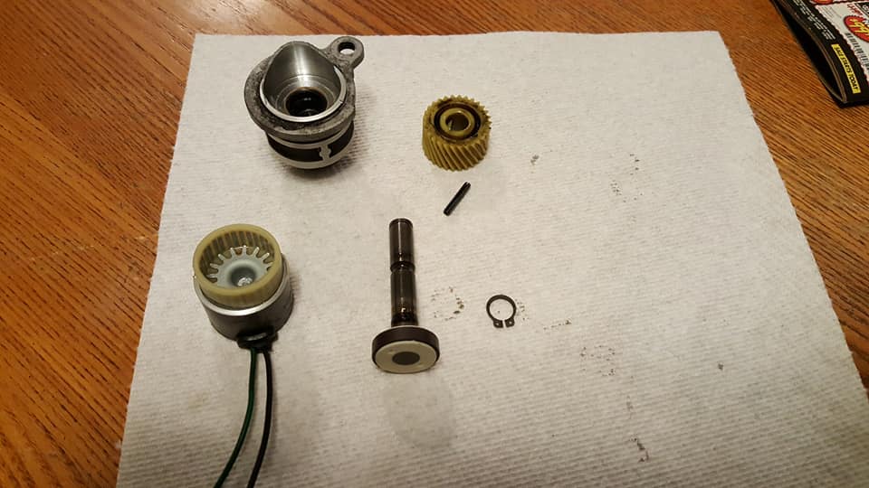
ive ordered a speed sensor from another car that appears to be the dimensions i need and it might just plug right in and work, it was only 17 dollars so even if it doesnt work its not a big deal, ill just continue looking for the correct speed sensor i need and possibly get the mechanical one and mate these two together. that would be relatively easy to do from the looks of it and it wouldnt be very costly to do (unlike buying a new speed sensor which looks to be more like 250 dollars, it will be a cold day in hell when i spend that much on a speed sensor)
OR if anyone has it or if i can find it i was originally considering putting a digital cluster in the car which would allow me to use a mechanical speed sensor and a mechanical to digital converter. idk if that cluster would fit or how difficult that would be, i kinda dont want to pull the interior apart again since i just finally put it all back together the other night but if that ends up being cheaper or more reliable than my other options im willing to humor it. we will see. ill probably be test driving the car this weekend tho so videos of that are coming soon.
the lase gauge i have to sort out is the speedometer. ive been trying to source a speed sensor for a while now but i had this one from the auto trans i got off of that maxima a while ago but it didnt fit into the other trans, the diameter of the holes are slightly different so the first thing i did was put it in my lathe to turn it down. i knew i couldnt use this speed sensor without modifying it further anyway i just wanted to plug up the hole in my trans with it in the mean time if i decide to drive the car.
so after i did this i tested the fit and it does physically fit into the hole now but the oring is a little too tight for it to go all the way in so i need to relieve the oring more if its going to be a plug but next thing i wanted to see was how it worked and if i could use the electronic internals of this speed sensor and mate them to a mechanical speed sensor to have a working speed sensor for the stanza since a mechanical speed sensor is easier to get than the proper electric one. back to the lathe it went...
after i cut the groove all i had to do was twist a screwdriver in there and the top popped right off.
and here are all the major components of the speed sensor. its a pretty simple part, it appears to me to essentially just be a tiny generator, a permanent magnet spins inside of a cage that generates a voltage which is sent directly to the speedometer, so the faster it spins, the higher the voltage the higher the speedo reads. so the speedo is basically the same as a voltmeter.
ive ordered a speed sensor from another car that appears to be the dimensions i need and it might just plug right in and work, it was only 17 dollars so even if it doesnt work its not a big deal, ill just continue looking for the correct speed sensor i need and possibly get the mechanical one and mate these two together. that would be relatively easy to do from the looks of it and it wouldnt be very costly to do (unlike buying a new speed sensor which looks to be more like 250 dollars, it will be a cold day in hell when i spend that much on a speed sensor)
OR if anyone has it or if i can find it i was originally considering putting a digital cluster in the car which would allow me to use a mechanical speed sensor and a mechanical to digital converter. idk if that cluster would fit or how difficult that would be, i kinda dont want to pull the interior apart again since i just finally put it all back together the other night but if that ends up being cheaper or more reliable than my other options im willing to humor it. we will see. ill probably be test driving the car this weekend tho so videos of that are coming soon.
Last edited by Nate Boslet; 05-18-2018 at 11:59 AM.
01-28-2018, 02:04 AM
#283

I have never dissected a speed sensor. My guess is that it is probably more of a transducer than a generator.
But its good to hear that you are just about done. This has been one major project. Your ability to weld and machine your own parts has allowed you to pull this off. There's no way I could have done this. Cudos.
But its good to hear that you are just about done. This has been one major project. Your ability to weld and machine your own parts has allowed you to pull this off. There's no way I could have done this. Cudos.
01-28-2018, 01:53 PM
#284
Member
Thread Starter
Join Date: Oct 2016
Posts: 284
I have never dissected a speed sensor. My guess is that it is probably more of a transducer than a generator.
But its good to hear that you are just about done. This has been one major project. Your ability to weld and machine your own parts has allowed you to pull this off. There's no way I could have done this. Cudos.
But its good to hear that you are just about done. This has been one major project. Your ability to weld and machine your own parts has allowed you to pull this off. There's no way I could have done this. Cudos.
thank you for the compliment, im thankful i have the skills to do this stuff but i do wish i had more resources to bring the quality up a little bit (or a lot lol) but im definitely not anywhere near finished, i still have to install the MS1 in order to actually drive the car because right now it wont hold an idle below 1500RPM idk if i mentioned that earlier. im going to get started on that this week, ill be completely redoing the harness too so its all tucked and shortened and looking nice. while im driving the car i plan on getting started on the turbo headers as well and then putting all of that stuff into motion so theres at least 5-10 more pages of stuff for the car. im not sure when it will all be coming since im going to enjoy driving the car but then again installing all of the turbo stuff onto the car should realistically only take a day or two once its all done. the downpipe and intake pipe will probably be one of the only things i really need to do on the car but we will see. in the mean time ill be collecting parts and materials for that.
02-04-2018, 07:30 AM
#285
Member
Thread Starter
Join Date: Oct 2016
Posts: 284
finally got around to turning the stanza around last night so i could let it warm all the way up without filling the garage with exhaust and killing myself.
https://www.youtube.com/watch?v=8SH-...ature=youtu.be
it wouldnt idle below 1500rpm which makes sense without the AIC but i did this mainly to see if i could burn all the oil off of the exhaust which i nearly did and also to see if the cooling system was working properly and that is also working great. im pretty much positive there is air in the system and it still never made it to the middle of the gauge (of course it was also 20 degrees in the garage) to make sure i get all the air out of the system im gonna put a bleeder in the coolant neck which is the highest point in the system.
the oil pressure gauge seems to be working and it looks like my oil pressure is good.
https://www.youtube.com/watch?v=hZgM...ature=youtu.be
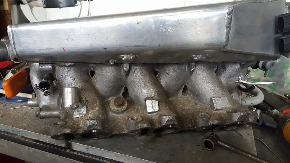
so after doing all this i drained the coolant, pulled the intake manifold and the wiring harness to get everything ready for the MS1 install. i need to install some vacuum ports and the main coolant sensor in the intake and im going to thin the harness out further, rerout some stuff and loom it and it should be a lot cleaner when im done and ill be able to set my idle wherever i want. im hoping to have all of this done by next weekend at the absolute latest so hopefully another video of the car running really well will be coming next weekend.
https://www.youtube.com/watch?v=8SH-...ature=youtu.be
it wouldnt idle below 1500rpm which makes sense without the AIC but i did this mainly to see if i could burn all the oil off of the exhaust which i nearly did and also to see if the cooling system was working properly and that is also working great. im pretty much positive there is air in the system and it still never made it to the middle of the gauge (of course it was also 20 degrees in the garage) to make sure i get all the air out of the system im gonna put a bleeder in the coolant neck which is the highest point in the system.
the oil pressure gauge seems to be working and it looks like my oil pressure is good.
https://www.youtube.com/watch?v=hZgM...ature=youtu.be
so after doing all this i drained the coolant, pulled the intake manifold and the wiring harness to get everything ready for the MS1 install. i need to install some vacuum ports and the main coolant sensor in the intake and im going to thin the harness out further, rerout some stuff and loom it and it should be a lot cleaner when im done and ill be able to set my idle wherever i want. im hoping to have all of this done by next weekend at the absolute latest so hopefully another video of the car running really well will be coming next weekend.
02-05-2018, 09:58 AM
#286
Getting all the air out of the VG engine was always a problem. Putting a bleeder in the filler neck won't help. Nissan's official policy was to raise the front end of the car 39 inches! I never did that, I just parked in my driveway that was a mild slope, definitely not 30 inches and less than my car ramps. You run the engine with the radiator cap off until the coolant stops bubbling. Be careful - the initial surge of air may blow coolant out into the air.
A bleeder port was added in later production, 93 and 94. It was a bolt screwed in on the right side of the engine, the firewall side as the engine sat in the car.
I'm looking for a photo. If I can find it, I will post it.
EDIT.....
I couldn't find a photo but I found a thread that sort of describes the location.
Read posts 7, 8, 9 & 10 - maxima.org/forums/3rd-generation-maxima-1989-1994/203147-bleeding-coolant-system.html
Last edited by DennisMik; 02-05-2018 at 10:57 AM.
02-05-2018, 05:28 PM
#287
Member
Thread Starter
Join Date: Oct 2016
Posts: 284
Getting all the air out of the VG engine was always a problem. Putting a bleeder in the filler neck won't help. Nissan's official policy was to raise the front end of the car 39 inches! I never did that, I just parked in my driveway that was a mild slope, definitely not 30 inches and less than my car ramps. You run the engine with the radiator cap off until the coolant stops bubbling. Be careful - the initial surge of air may blow coolant out into the air.
A bleeder port was added in later production, 93 and 94. It was a bolt screwed in on the right side of the engine, the firewall side as the engine sat in the car.
I'm looking for a photo. If I can find it, I will post it.
EDIT.....
I couldn't find a photo but I found a thread that sort of describes the location.
Read posts 7, 8, 9 & 10 - maxima.org/forums/3rd-generation-maxima-1989-1994/203147-bleeding-coolant-system.html
A bleeder port was added in later production, 93 and 94. It was a bolt screwed in on the right side of the engine, the firewall side as the engine sat in the car.
I'm looking for a photo. If I can find it, I will post it.
EDIT.....
I couldn't find a photo but I found a thread that sort of describes the location.
Read posts 7, 8, 9 & 10 - maxima.org/forums/3rd-generation-maxima-1989-1994/203147-bleeding-coolant-system.html
02-06-2018, 05:10 AM
#288

I had a 92 vg max and there was actually an 8mm bleeder screw on the top right side of the intake manifold. Looking forward to seeing everything go smoothly and you getting the stanzima out for a good run ☺ Just curious. Did you ever happen to get the window switch and parts you were looking for?
Last edited by ac max 92; 02-06-2018 at 05:12 AM.
02-06-2018, 10:05 PM
#289
Member
Thread Starter
Join Date: Oct 2016
Posts: 284
I had a 92 vg max and there was actually an 8mm bleeder screw on the top right side of the intake manifold. Looking forward to seeing everything go smoothly and you getting the stanzima out for a good run ☺ Just curious. Did you ever happen to get the window switch and parts you were looking for?
02-06-2018, 10:34 PM
#290
Member
Thread Starter
Join Date: Oct 2016
Posts: 284
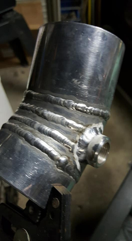
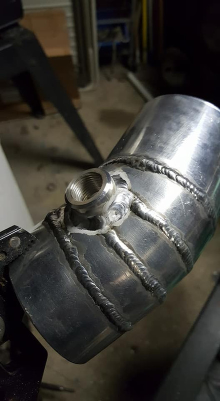
did some of the intake mods today, dont have a bleeder yet and im not sure im going to need it now but we will see i guess. i started off drilling and tapping the hole for the GM intake air temp sensor in the coolant manifold in the intake. this plug's gotta go.
it was REALLY in there.....
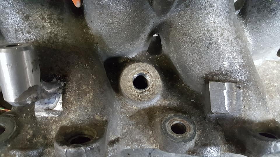
once i put the correct size socket on it and threw a little heat at it she did me a favor.

drilled
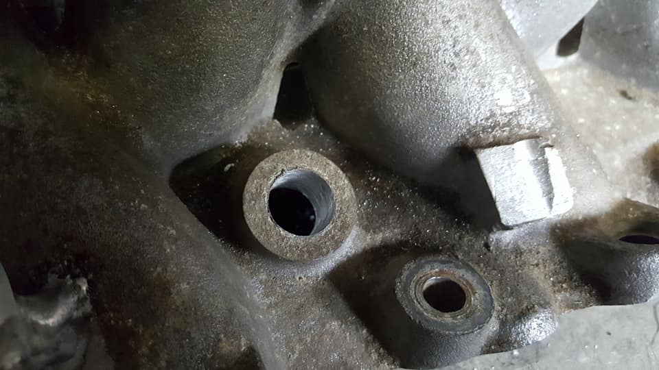
tapped

sensor installed

all said and done. plenty of room and functional.

i also turned up a bung for the intake air temp sensor. i forgot to grab the pie cut intake pipe thing the other night (along with a lot of other stuff ill have to get later today..)

i stripped the harness a little bit, got rid of all of the stuff i know im not going to need. i have to bring it back to the car to get all the circuits cut to length but after thats done ill probably be able to finish the harness by friday and get everything ready to go back in the car this weekend like im aiming for. ill try to take plenty of pics of that process for the next update since theres going to be a lot to go over.
it was REALLY in there.....
once i put the correct size socket on it and threw a little heat at it she did me a favor.
drilled
tapped
sensor installed
all said and done. plenty of room and functional.
i also turned up a bung for the intake air temp sensor. i forgot to grab the pie cut intake pipe thing the other night (along with a lot of other stuff ill have to get later today..)
i stripped the harness a little bit, got rid of all of the stuff i know im not going to need. i have to bring it back to the car to get all the circuits cut to length but after thats done ill probably be able to finish the harness by friday and get everything ready to go back in the car this weekend like im aiming for. ill try to take plenty of pics of that process for the next update since theres going to be a lot to go over.
Last edited by Nate Boslet; 05-18-2018 at 12:01 PM.
02-08-2018, 09:37 PM
#291
Member
Thread Starter
Join Date: Oct 2016
Posts: 284
made my trip back and grabbed all the stuff i needed. welded the bung into the intake pipe thing.


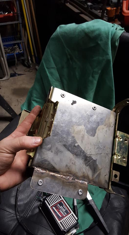
so initially i was going to put the ecu in the glovebox like i did in the z, but the glovebox in the stanza is kinda small, it didnt really matter when it was just the MS1 but im also going to run an ignition box (not really because i feel its necessary, its definitely not, but i have it and its not going back in the z so why not. plus it makes wiring easier.) so i need space for that too. i noticed the ignition box is almost the exact same size as the TCM and what better place to keep my ecu than the stock location? so thats what im gonna do. ill have to modify the brackets quite a bit for them to hold everything but once its done it will occupy essentially the same space as the stock stuff did so i get to keep my glovebox im never going to use. yay.
heres the MS1 which is almost the same length as the stock ecu but about half as wide.
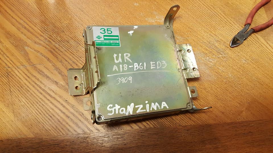
heres the stock ecu as you have seen it before. the auto trans control module bolts onto those tabs with a little bracket thats where the ignition box will go, ill take more pics when i do that tomorrow.
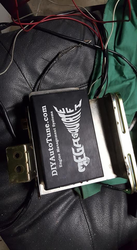
and here is the ignition box. its going to be mounted vertically and the MS1 is going to be horizontal in relation to this picture. again ill show what i mean tomorrow, the mounting stuff shouldnt take much time at all.

i put like 4 hours into the harness today, everything that goes on the intake is done, ive taken a few pics but im gonna try to get the harness completely finished before i make a post about it. its not super complicated so there wont be too much to go over but theres gonna be a lot of pics. im gonna run up to the garage tomorrow afternoon to get all of the lengths locked in so everything fits perfect and then i should definitely be finished by the weekend and see if the car runs with all this crap.
so initially i was going to put the ecu in the glovebox like i did in the z, but the glovebox in the stanza is kinda small, it didnt really matter when it was just the MS1 but im also going to run an ignition box (not really because i feel its necessary, its definitely not, but i have it and its not going back in the z so why not. plus it makes wiring easier.) so i need space for that too. i noticed the ignition box is almost the exact same size as the TCM and what better place to keep my ecu than the stock location? so thats what im gonna do. ill have to modify the brackets quite a bit for them to hold everything but once its done it will occupy essentially the same space as the stock stuff did so i get to keep my glovebox im never going to use. yay.
heres the MS1 which is almost the same length as the stock ecu but about half as wide.
heres the stock ecu as you have seen it before. the auto trans control module bolts onto those tabs with a little bracket thats where the ignition box will go, ill take more pics when i do that tomorrow.
and here is the ignition box. its going to be mounted vertically and the MS1 is going to be horizontal in relation to this picture. again ill show what i mean tomorrow, the mounting stuff shouldnt take much time at all.
i put like 4 hours into the harness today, everything that goes on the intake is done, ive taken a few pics but im gonna try to get the harness completely finished before i make a post about it. its not super complicated so there wont be too much to go over but theres gonna be a lot of pics. im gonna run up to the garage tomorrow afternoon to get all of the lengths locked in so everything fits perfect and then i should definitely be finished by the weekend and see if the car runs with all this crap.
Last edited by Nate Boslet; 05-18-2018 at 12:01 PM.
02-11-2018, 11:42 AM
#293
Member
Thread Starter
Join Date: Oct 2016
Posts: 284
had a couple holdups this week so im a little behind but i got the harness mostly done. should be totally finished pretty soon after i go pick up some stuff.
i had to rerun almost everything cause nothing was the way i wanted it and a lot of the joints were done kind of poorly. if i had a kit to redo the pins and stuff on a full piece of wire and stuff i would have but anyway this is how it looks about half way through on one side:
then fully finished with loom.

other side done, i know the tps pins are ****ed, im going to redo them at some point, they are just the only pins i have right now and they worked fine before so they should survive until i can get to the junkyard and grab new ones.
loomed up the split.

i had to bring the harness back to the car to make sure my lengths were still right and everything was going to fit up the way i needed it to, i cut some of the wires off and made sure the ecu was going to fit in the space the stock ecu was (it does) once i got that all straight i could pretty much finish this end of the harness, i still need to run a ground strap through and maybe one or two other things but its gonna look basically the same it will just have one more wire branching out.


so ill do the main plug, the brackets for the ecu and ignition box and maybe put it all on the car tonight and see if i can get some inputs and stuff to light up, maybe even give it a crank (probably not but we will see lol)
i had to rerun almost everything cause nothing was the way i wanted it and a lot of the joints were done kind of poorly. if i had a kit to redo the pins and stuff on a full piece of wire and stuff i would have but anyway this is how it looks about half way through on one side:
then fully finished with loom.
other side done, i know the tps pins are ****ed, im going to redo them at some point, they are just the only pins i have right now and they worked fine before so they should survive until i can get to the junkyard and grab new ones.
loomed up the split.
i had to bring the harness back to the car to make sure my lengths were still right and everything was going to fit up the way i needed it to, i cut some of the wires off and made sure the ecu was going to fit in the space the stock ecu was (it does) once i got that all straight i could pretty much finish this end of the harness, i still need to run a ground strap through and maybe one or two other things but its gonna look basically the same it will just have one more wire branching out.
so ill do the main plug, the brackets for the ecu and ignition box and maybe put it all on the car tonight and see if i can get some inputs and stuff to light up, maybe even give it a crank (probably not but we will see lol)
Last edited by Nate Boslet; 05-18-2018 at 12:02 PM.
02-11-2018, 10:34 PM
#294
Member
Thread Starter
Join Date: Oct 2016
Posts: 284
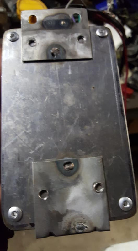
got the mounting bracketry banged out earlier. first i needed to make a plate that will take up the space of the stock ecu and give me something to mount the megasquirt to. i had this piece of scrap lying around that was almost the perfect width and already had a bend in it.

i made up a plate to mount the ignition box that ill replace the tcm plate with.

cut the brackets off of the old plate so i could reuse them.

then i tacked them onto the plate. you can see the other panel i bent up, i thought i took other pictures of that before i welded it on but apparently not.

initially i expected to need a whole bunch of fasteners for this but i realized i that 1. i dont have any that would be good for this application and 2. i have no real reason to take this stuff off of the bracket unless its completely leaving the car entirely... so i opted for rivets.
the ignition box
and the MS1, as you can see that plate wasnt quite wide enough so i had to add a little extra onto that part.
assebled and ready to be installed.

i didnt get a chance to run out and get the stuff i needed today so the harness is gonna have to wait till tomorrow but hopefully ill be able to get that done and then finally get this stuff all thrown back onto the car.
i made up a plate to mount the ignition box that ill replace the tcm plate with.
cut the brackets off of the old plate so i could reuse them.
then i tacked them onto the plate. you can see the other panel i bent up, i thought i took other pictures of that before i welded it on but apparently not.
initially i expected to need a whole bunch of fasteners for this but i realized i that 1. i dont have any that would be good for this application and 2. i have no real reason to take this stuff off of the bracket unless its completely leaving the car entirely... so i opted for rivets.
the ignition box
and the MS1, as you can see that plate wasnt quite wide enough so i had to add a little extra onto that part.
assebled and ready to be installed.
i didnt get a chance to run out and get the stuff i needed today so the harness is gonna have to wait till tomorrow but hopefully ill be able to get that done and then finally get this stuff all thrown back onto the car.
Last edited by Nate Boslet; 05-18-2018 at 12:02 PM.
02-22-2018, 08:58 PM
#295
Member
Thread Starter
Join Date: Oct 2016
Posts: 284
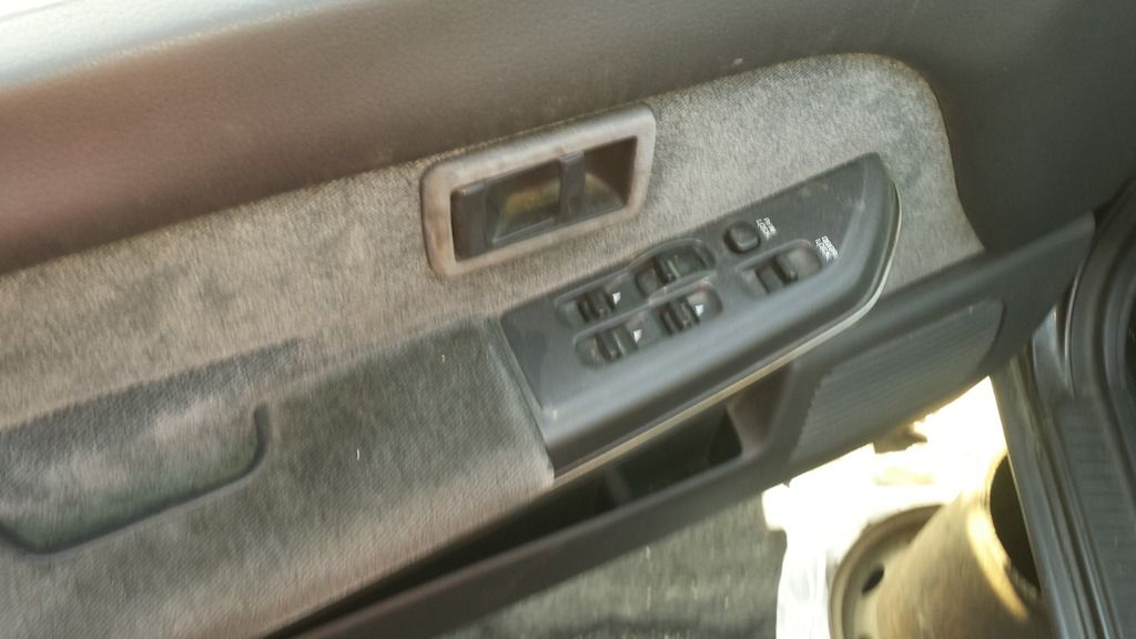
got my window switch in the mail today and noticed some of the switches were broken. i have taken these switches apart before and knew that the mechanism is usually separate from the actual switch that you touch so they can make all of the expensive switches the same and then change the colors or whatever for each individual switch. as soon as i took the panel off the two switches sort of just fell out of the cover and i saw exactly what the problem was. the switches are held on by a little socket that snaps over the actual mechanism and the sockets had broken apart. both switches failed in the same way, the front and back walls of the socket broke off (those two black square things are little dust boots)
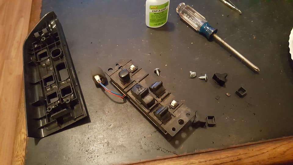
the one was totally missing one of the little sides to the socket so i couldnt glue that back in but i basically just glued the entire switch onto the little stud thing and they shouldnt ever come off again, i have no reason to need to remove them so this was the best solution for me. once the glue dried the switches all seemed to operate how they should.

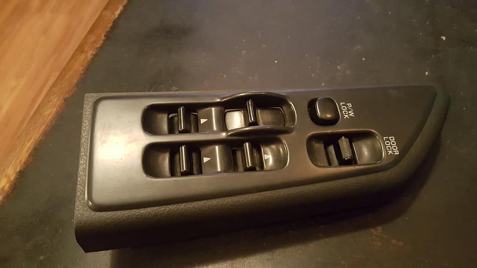
l brought everything back to the garage, including the intake and harness, and after installing the intake and whatever other loose ends in the engine bay i needed to take care of i slapped the window switch in the door and powered it up and it all works the way its supposed to. pretty stoked about that.
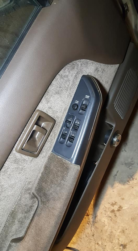
only one problem..... the window not being up had nothing to do with the switch, the window was up as far as it will go.. what actually happened was the window somehow came off of the track or something and pinched the seal and now it cant get back into the little crack its supposed to fit into so it just wont go all the way up.... im not sure how im going to have to fix this, maybe a new regulator and seal. i messed with the seal and got it completely unpinched and the window still couldnt fully close so i think this may be a problem with the guide inside the door. ill have to investigate that later but the window is definitely sluggish so it might be time for a replacement either way. regardless, im pretty happy my door doesnt have a massive hole in it anymore and i use my windows again.
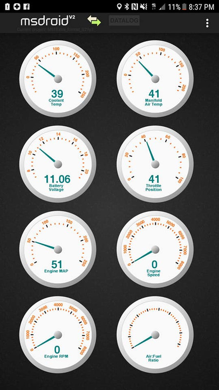
so after i was done with that which really only took a few minutes i moved onto the harness. as usual the harness took maybe a full minute to install on the car and then i put the ecu and ignition box assembly in place and plugged everything in. i hooked the battery back up and turned the key and the first thing i hear is the fuel pump kick on, thats a good sign, i get out my phone and see if i can get it to connect to the ecu, it does. thats a good sign too. i look at the gauges on my phone, they all show correct values (except the MAP, idk why that one is so far off but it might just be the app, ive had that happen before. i was messing with the tps and realized that wasnt working so i looked at the harness and of course the wires i wanted to have replaced already broke off at the sensor so ill have to replace those sooner rather than later lol but anyway the harness works, the ecu seems to be working. i need to finish some stuff like the ignition harness and some little plugs here and there but if everything keeps going this smoothly the car should be running very soon.
the one was totally missing one of the little sides to the socket so i couldnt glue that back in but i basically just glued the entire switch onto the little stud thing and they shouldnt ever come off again, i have no reason to need to remove them so this was the best solution for me. once the glue dried the switches all seemed to operate how they should.
l brought everything back to the garage, including the intake and harness, and after installing the intake and whatever other loose ends in the engine bay i needed to take care of i slapped the window switch in the door and powered it up and it all works the way its supposed to. pretty stoked about that.
only one problem..... the window not being up had nothing to do with the switch, the window was up as far as it will go.. what actually happened was the window somehow came off of the track or something and pinched the seal and now it cant get back into the little crack its supposed to fit into so it just wont go all the way up.... im not sure how im going to have to fix this, maybe a new regulator and seal. i messed with the seal and got it completely unpinched and the window still couldnt fully close so i think this may be a problem with the guide inside the door. ill have to investigate that later but the window is definitely sluggish so it might be time for a replacement either way. regardless, im pretty happy my door doesnt have a massive hole in it anymore and i use my windows again.
so after i was done with that which really only took a few minutes i moved onto the harness. as usual the harness took maybe a full minute to install on the car and then i put the ecu and ignition box assembly in place and plugged everything in. i hooked the battery back up and turned the key and the first thing i hear is the fuel pump kick on, thats a good sign, i get out my phone and see if i can get it to connect to the ecu, it does. thats a good sign too. i look at the gauges on my phone, they all show correct values (except the MAP, idk why that one is so far off but it might just be the app, ive had that happen before. i was messing with the tps and realized that wasnt working so i looked at the harness and of course the wires i wanted to have replaced already broke off at the sensor so ill have to replace those sooner rather than later lol but anyway the harness works, the ecu seems to be working. i need to finish some stuff like the ignition harness and some little plugs here and there but if everything keeps going this smoothly the car should be running very soon.
Last edited by Nate Boslet; 05-18-2018 at 12:03 PM.
02-22-2018, 09:48 PM
#296
Excellent!
The window may not need any pieces. The window slides in tracks that have some small amount of adjustment to fit the width of the window. You take off the inside door panel trim and look towards the bottom ends of the tracks and you should be able to see the mounting bolts that give you the adjusting ability. Hopefully you can loosen the tracks and get enough play to get the glass back in position.
Working on windows is a lot of trial and error and swearing. Part of the difficulties you encounter are due to the position of the glass & regulator allowing you access to the various bolts. Sometimes you can take the glass off of the regulator (2 bolts) to give you access to other things but again the window position might make this hard.
02-23-2018, 11:10 AM
#297
Member
Thread Starter
Join Date: Oct 2016
Posts: 284
Excellent!
The window may not need any pieces. The window slides in tracks that have some small amount of adjustment to fit the width of the window. You take off the inside door panel trim and look towards the bottom ends of the tracks and you should be able to see the mounting bolts that give you the adjusting ability. Hopefully you can loosen the tracks and get enough play to get the glass back in position.
Working on windows is a lot of trial and error and swearing. Part of the difficulties you encounter are due to the position of the glass & regulator allowing you access to the various bolts. Sometimes you can take the glass off of the regulator (2 bolts) to give you access to other things but again the window position might make this hard.
The window may not need any pieces. The window slides in tracks that have some small amount of adjustment to fit the width of the window. You take off the inside door panel trim and look towards the bottom ends of the tracks and you should be able to see the mounting bolts that give you the adjusting ability. Hopefully you can loosen the tracks and get enough play to get the glass back in position.
Working on windows is a lot of trial and error and swearing. Part of the difficulties you encounter are due to the position of the glass & regulator allowing you access to the various bolts. Sometimes you can take the glass off of the regulator (2 bolts) to give you access to other things but again the window position might make this hard.
its weird cause i dont remember ever having that issue but now im wondering if i just never noticed lol there has never been any water in the car but i also never really used that window so who knows. regardless im gonna pop the door panel off at some point and check it out. hopefully something is obviously screwed up. that window did seem to have a lot more slop in it than the others so i think it should be relatively apparent once im in there.
 03-08-2018, 07:20 PM
#299
Member
Thread Starter
Join Date: Oct 2016
Posts: 284
ive been super busy lately with other work and getting certified to do inspections. ive been making progress here and there but not enough for an update. i should have the harness ready to go in for the startup test next week after im done with a lot of this other work. i appreciate the check in, i need the extra motivation right now lol
03-21-2018, 09:13 PM
#300
Member
Thread Starter
Join Date: Oct 2016
Posts: 284
https://www.youtube.com/watch?v=BKjz...ature=youtu.be
heres the efans being tested, i have the harness almost completely done i just have to add the coil plug and test it, then its getting potted because the cover for the plug doesnt fit over all of my wires. i have all of the outputs i need for boost control and fan control and all of that stuff, i might set up launch control and i was planning on setting up my check engine light as my shift light but i have to do internal mods to the MS1 box itself for that so im not gonna mess with it until i know everything is working. i should be able to test everything once all this snow melts so knowing PA that will be saturday. i will have a lot more time to work on this by then so ill post an update soon.
heres the efans being tested, i have the harness almost completely done i just have to add the coil plug and test it, then its getting potted because the cover for the plug doesnt fit over all of my wires. i have all of the outputs i need for boost control and fan control and all of that stuff, i might set up launch control and i was planning on setting up my check engine light as my shift light but i have to do internal mods to the MS1 box itself for that so im not gonna mess with it until i know everything is working. i should be able to test everything once all this snow melts so knowing PA that will be saturday. i will have a lot more time to work on this by then so ill post an update soon.
04-27-2018, 02:34 PM
#301
Member
Thread Starter
Join Date: Oct 2016
Posts: 284
i finally got a few days to basically live at my garage and sort everything out and after about 16 hours i finally got the car running on the ms1. this is literally the second time i started the car that night, theres several vacuum leaks, the gas is old as hell and i made absolutely no changes to the tune or any of the settings but one im done with the few other things i want to do ill start taking data logs and get it all dialed in.
https://www.youtube.com/watch?v=GKLg...ature=youtu.be
i want the plug to be basically bomb proof so i used a small strip of plastic to separate the two rows of pins on the plug, its kind of hard to see here.

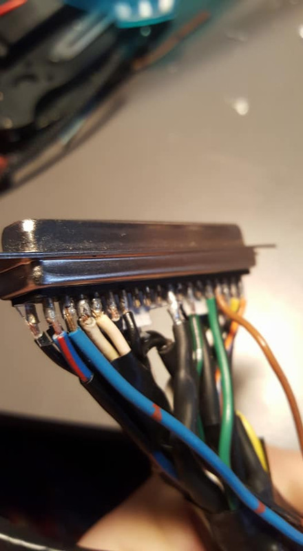
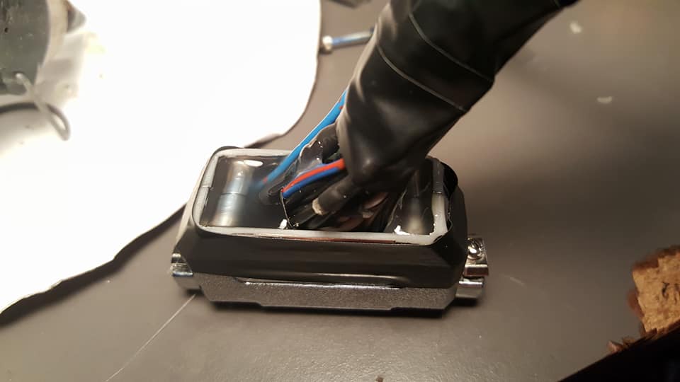
then i filled the clamshell with hot glue. this should pretty much prevent any possibility of contamination or breakage in the entire area.

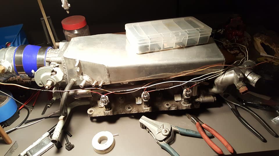
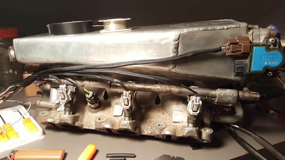
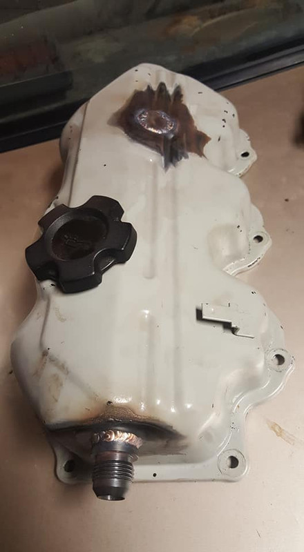
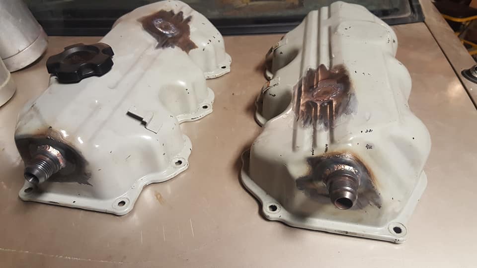
once the harness was all loomed and wrapped up i moved onto the valve covers. ive had the breathers just kind of open to the atmosphere for a while, which i could probably have just put little filters on them but i dont really want a bunch of oil to spray all over my engine bay if i begin to get a lot of blow by on boost so im going to install a catch can. first i took the fittings from my z and welded them onto the stanzas valve covers.
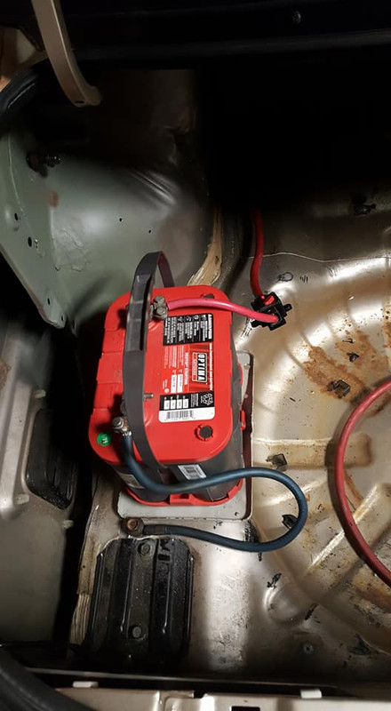
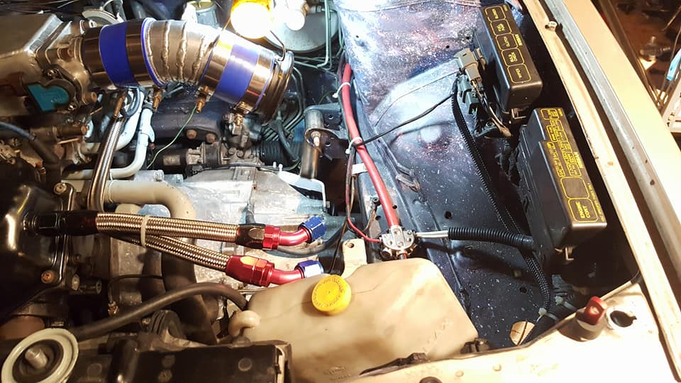
since space is a little cramped as it is in the engine bay and i need to do it anyway if im ever going to fit a turbo in here i decided to get started on relocating the battery. if youre considering doing a battery relocation get yourself one of these little power blocks, they make installing and running the wires everywhere way cleaner and easier than any other way ive seen it done.

im going to loom up everything else in this area and try to clean it up and tuck it all as best as i can and then move onto the catch can and coolant overflow tank which i may combine into the same box.

i think im going to just use the original battery tray and bolt it into the trunk here. ill run a ground into the frame and make sure i run a fat *** ground for the engine up front too right into the main rail as well.

https://www.youtube.com/watch?v=GKLg...ature=youtu.be
i want the plug to be basically bomb proof so i used a small strip of plastic to separate the two rows of pins on the plug, its kind of hard to see here.
then i filled the clamshell with hot glue. this should pretty much prevent any possibility of contamination or breakage in the entire area.
once the harness was all loomed and wrapped up i moved onto the valve covers. ive had the breathers just kind of open to the atmosphere for a while, which i could probably have just put little filters on them but i dont really want a bunch of oil to spray all over my engine bay if i begin to get a lot of blow by on boost so im going to install a catch can. first i took the fittings from my z and welded them onto the stanzas valve covers.
since space is a little cramped as it is in the engine bay and i need to do it anyway if im ever going to fit a turbo in here i decided to get started on relocating the battery. if youre considering doing a battery relocation get yourself one of these little power blocks, they make installing and running the wires everywhere way cleaner and easier than any other way ive seen it done.
im going to loom up everything else in this area and try to clean it up and tuck it all as best as i can and then move onto the catch can and coolant overflow tank which i may combine into the same box.
i think im going to just use the original battery tray and bolt it into the trunk here. ill run a ground into the frame and make sure i run a fat *** ground for the engine up front too right into the main rail as well.
04-28-2018, 10:47 AM
#302
Good to hear from you again. Electrical work is my strong point and you have done things that the pros do. Like the plastic strip between the rows of the wire connector.
When I relocated a battery to the trunk, I had custom battery cables made. They were about 15 feet long and made with thick, probably overkill, 0000 gauge cable. Connected them under the hood where the stock battery cables connected and never had a problem, even in below zero weather.
When I relocated a battery to the trunk, I had custom battery cables made. They were about 15 feet long and made with thick, probably overkill, 0000 gauge cable. Connected them under the hood where the stock battery cables connected and never had a problem, even in below zero weather.
04-29-2018, 10:27 PM
#303
Member
Thread Starter
Join Date: Oct 2016
Posts: 284
idk if you can tell but the cable i used is absolutely massive. i think its 0 but its like 100 strands or something so super heavy, not flexible at all but im sure in a pinch i could use it to patch a power line. it just BARELY fits in the distribution block and my circuit breaker. im going to make a plate to mount the distribution block too so that isnt just floating there and then i can manage all the loose wires and stuff.

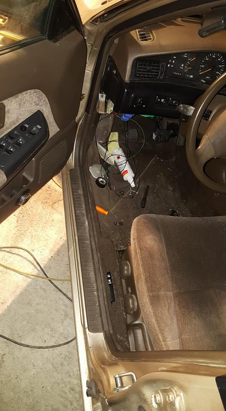
speaking of barely fitting this is my interior AFTER running the cable through it, i spent another 16 hour day at the garage and spent very little of that time taking pictures but i removed half of my interior and my drivers seat to get the cable underneath the main wire cover thing that runs along the rocker, there was absolutely no possible way to run this cable any other way, usually there is room down there to just kind of stuff the cable along the rocker and then the carpet and trim covers it up but if i did that there would be a huge bulge all the way along it and thus a larger chance to rub through the shielding somewhere and cause a short and with this cable im sure that would result in a massive puddle of liquid steel...... if i didnt have a breaker that is.. anyway if you arent looking for it you wont see it, once the dash trim is back on its gonna be essentially impossible for anyone to spot the massive cable from the interior which is what i wanted.
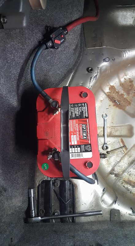
this is obviously temporary i need to make a mounting bracket for the breaker and change up the lengths for these leads a bit. i ordered new solder on battery terminals because these clamp on ones are complete trash, i pulled a bolt right through the one trying to get it semi tight but i wont have to worry about that in a few days.
so im gonna work on getting the brackets and plates made up next and then paint the valve covers and get all of that back together and then i can start working on getting the car tuned and idling properly.
speaking of barely fitting this is my interior AFTER running the cable through it, i spent another 16 hour day at the garage and spent very little of that time taking pictures but i removed half of my interior and my drivers seat to get the cable underneath the main wire cover thing that runs along the rocker, there was absolutely no possible way to run this cable any other way, usually there is room down there to just kind of stuff the cable along the rocker and then the carpet and trim covers it up but if i did that there would be a huge bulge all the way along it and thus a larger chance to rub through the shielding somewhere and cause a short and with this cable im sure that would result in a massive puddle of liquid steel...... if i didnt have a breaker that is.. anyway if you arent looking for it you wont see it, once the dash trim is back on its gonna be essentially impossible for anyone to spot the massive cable from the interior which is what i wanted.
this is obviously temporary i need to make a mounting bracket for the breaker and change up the lengths for these leads a bit. i ordered new solder on battery terminals because these clamp on ones are complete trash, i pulled a bolt right through the one trying to get it semi tight but i wont have to worry about that in a few days.
so im gonna work on getting the brackets and plates made up next and then paint the valve covers and get all of that back together and then i can start working on getting the car tuned and idling properly.
04-30-2018, 09:54 AM
#304
I really hope this isn't a stay tuned for next summer. So looking forward to a YouTube vid of the stanzima peelin rubber lol.. I'd be curious what it's putting down at the wheels once it's all tuned. I can see it now.. WORLD'S.. first.. STANSIMA. I'm sure you must be looking forward to driving the fruits of your time and labour. A lot put into that car. Keep up the good work Nate.
04-30-2018, 01:20 PM
#305
I still have my long battery cables so I dug them out and looked at how thick they are. They are 0000 gauge like I thought. 0000 gauge wire is .48 inches thick. 000 gauge is.42 inches thick. At that thickness, you want stranded wire or it would be like trying to run concrete rebar. I'm glad you will get the soldered battery connections, much better.
Like ac max 92, I want to see the "STANSIMA" terrorizing the streets. What's the chances of it being streetable by the 4th of July? I will be in Lansdale. I think that is about 30 miles south of you?
Like ac max 92, I want to see the "STANSIMA" terrorizing the streets. What's the chances of it being streetable by the 4th of July? I will be in Lansdale. I think that is about 30 miles south of you?
05-05-2018, 01:44 PM
#306
Member
Thread Starter
Join Date: Oct 2016
Posts: 284
no i wont be waiting till next summer in fact i could really drive the car the way it is now theres only 2 problems.
1. i am having the valve covers powder coated at my job and i dont want to run the filthy covers i have on there now (they are really just keeping concrete dust out of my motor) and i want to finish my catch can before i drive it.
2. my registration for the stanzima got suspended because my insurance lapsed when i got my current daily and gieco snitched on me cause i pulled the insurance off of the stanza while it sits in the garage doing nothing. the suspension will be up in july and then i can finally destroy some tires.
bonus problem. my daily drivers throwout bearing took a **** and ive been working basically every day for 12+ hours so ive had absolutely no time to mess with the stanza. its not really an issue since i barely have anything left to do and im sure once the honda is fixed (05 civic hybrid, great daily, everyone is always surprised its manual lol) ill get right back to the stanza to get it all squared away.
onto the meat of this update.
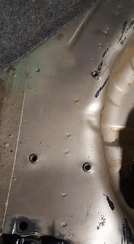
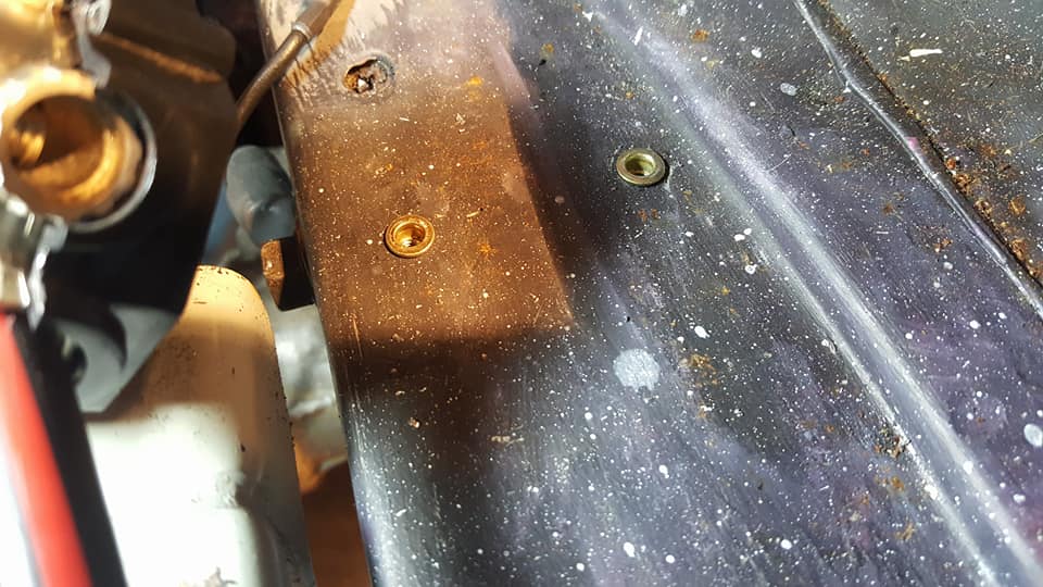
i recently got some threaded compression inserts or "nutserts" whatever you want to call them, they are awesome. i of course didnt buy the special tool you need for them i just drilled the threads out of a nut and held the nut with a wrench and used an impact gun to run a bolt into the threads and that works a champ, you just have to make sure the nut seats tightly on the bolt because otherwise it will pull up some of the top seat of the insert into the gap and **** it up which happened once or twice. the threads are all fine tho. these are 12mm holes and the lower one i put 14mm in for the battery ground.
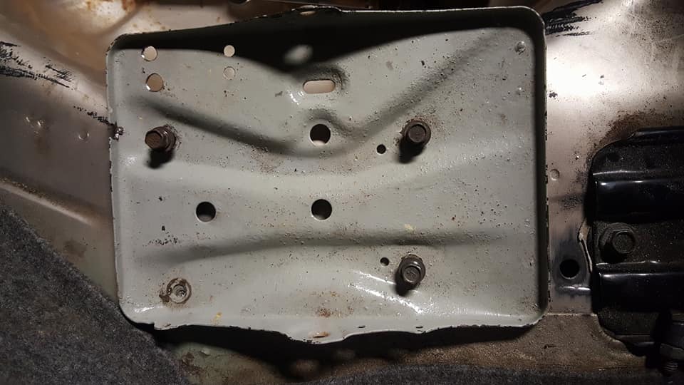
heres the tray bolted in. all the holes line up well.
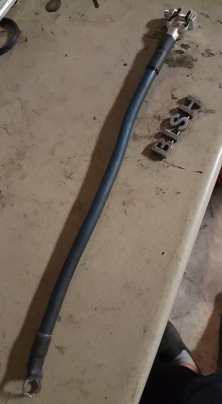
heres my ground strap, i like these solder on battery terminals a lot, they are very clean looking and easy to install, the other end is just a ring terminal thats bolted to the frame area of the trunk and of course you know ya boy had to use adhesive heat shrink to make this cable as resilient to the elements as possible.
here is the ground installed.

same story with the power side, i dont have any other really good 2 gauge cable thats a different color, i dont really care what color it is i just want it to work so my power and grounds are the same. the terminals are labeled tho so whatever. i still have to mount the breaker properly buti have done some voltage drop tests under very light loads (i will do it while the car is running soon) and the most ive seen yet was .02v IIRC so not very much at all.
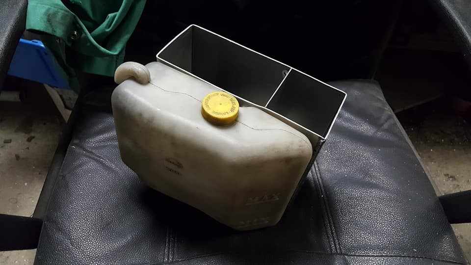
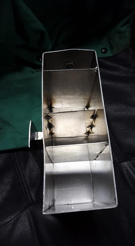
ok so here is my catch can idea. i was initially planning to make a coolant reservoir too but i realized i could reuse the stock one if i make a mount for it on the catch can itself so since thats the easiest and free thing to do obviously im doing that.
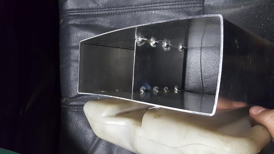
so far i only have one baffle in there, im adding 2 more between the fittings and the breather.
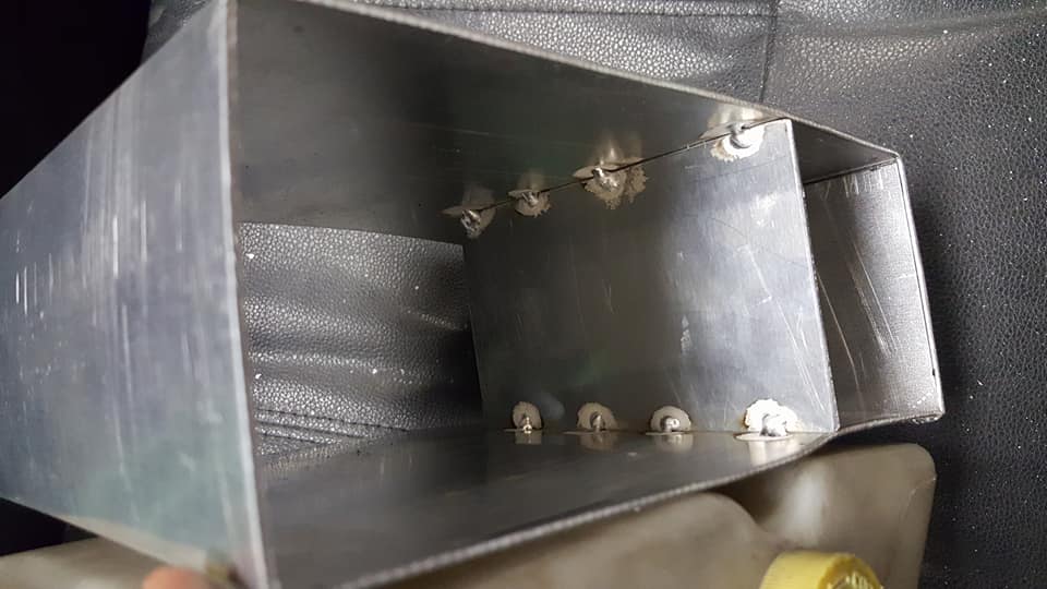
if the catch can looks warped to **** its because this material is way thinner than it should be (the material was also free) so i had to clamp it everywhere im trying to weld it otherwise the material will pull away.
so im gonna be working on this at home until the honda is fixed which will hopefully be done on sunday or monday and then i can get back to the car to begin tuning the idle and settings.
1. i am having the valve covers powder coated at my job and i dont want to run the filthy covers i have on there now (they are really just keeping concrete dust out of my motor) and i want to finish my catch can before i drive it.
2. my registration for the stanzima got suspended because my insurance lapsed when i got my current daily and gieco snitched on me cause i pulled the insurance off of the stanza while it sits in the garage doing nothing. the suspension will be up in july and then i can finally destroy some tires.
bonus problem. my daily drivers throwout bearing took a **** and ive been working basically every day for 12+ hours so ive had absolutely no time to mess with the stanza. its not really an issue since i barely have anything left to do and im sure once the honda is fixed (05 civic hybrid, great daily, everyone is always surprised its manual lol) ill get right back to the stanza to get it all squared away.
onto the meat of this update.
i recently got some threaded compression inserts or "nutserts" whatever you want to call them, they are awesome. i of course didnt buy the special tool you need for them i just drilled the threads out of a nut and held the nut with a wrench and used an impact gun to run a bolt into the threads and that works a champ, you just have to make sure the nut seats tightly on the bolt because otherwise it will pull up some of the top seat of the insert into the gap and **** it up which happened once or twice. the threads are all fine tho. these are 12mm holes and the lower one i put 14mm in for the battery ground.
heres the tray bolted in. all the holes line up well.
heres my ground strap, i like these solder on battery terminals a lot, they are very clean looking and easy to install, the other end is just a ring terminal thats bolted to the frame area of the trunk and of course you know ya boy had to use adhesive heat shrink to make this cable as resilient to the elements as possible.
here is the ground installed.
same story with the power side, i dont have any other really good 2 gauge cable thats a different color, i dont really care what color it is i just want it to work so my power and grounds are the same. the terminals are labeled tho so whatever. i still have to mount the breaker properly buti have done some voltage drop tests under very light loads (i will do it while the car is running soon) and the most ive seen yet was .02v IIRC so not very much at all.
ok so here is my catch can idea. i was initially planning to make a coolant reservoir too but i realized i could reuse the stock one if i make a mount for it on the catch can itself so since thats the easiest and free thing to do obviously im doing that.
so far i only have one baffle in there, im adding 2 more between the fittings and the breather.
if the catch can looks warped to **** its because this material is way thinner than it should be (the material was also free) so i had to clamp it everywhere im trying to weld it otherwise the material will pull away.
so im gonna be working on this at home until the honda is fixed which will hopefully be done on sunday or monday and then i can get back to the car to begin tuning the idle and settings.
05-13-2018, 10:53 AM
#308
Member
Thread Starter
Join Date: Oct 2016
Posts: 284
got the power block mounted up, i used some nut inserts in the frame rail for this.
i tucked a lot more of the harness as well. the engine harness is more tucked now as well but i forgot to get a picture of that last night.

heres the wiring all squared away nice and neat. i gotta admit now that ive gotten more into doing "professional" wiring i think im becoming ocd. ive never really cared about how anything looked but doing wiring meticulously really helps when you have to troubleshoot or just run wires and keep everything safe and working properly. if the improvement between the z to the stanza is any indication then when i redo the wiring in the z the attention to detail should be ridiculous lol
as you may have noticed my valve covers are back from my work and they are powder coated up and look awesome. im really happy with the way they came out, the only problem is now i might have to have everything else in my bay coated too....

i added some more baffles to the catch can....
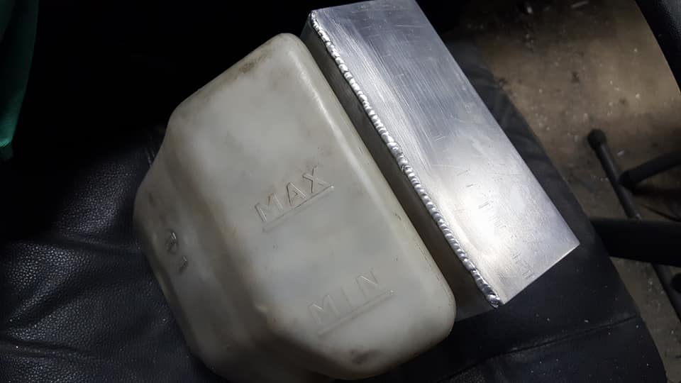
...some fittings and the bottom plate.

and here it is mocked up. i realized pretty much right away that im not going to be able to fit a huge filter like i was planning on using, i just wont have enough room on top and obviously i dont want to run a breather off of the size of the catch can lol so im gonna have to get creative with that solution. i already know what im going to do its just a matter of doing it and having it not look stupid or function poorly. more on that later.

once the catch can is done i dont have much else to do. i have to make a pin for the shifter to get rid of my aluminum bushings i made (big surprise, aluminum is a terrible bushing material, all they did was gall up and make the shifter super tight) and then mount my breaker a little better but thats pretty minor stuff. other than that i just need to figure out how to add a dipstick tube. i might do that soon because i still have some time on my registration suspension and i might redo the front engine and transmission mounts.
i tucked a lot more of the harness as well. the engine harness is more tucked now as well but i forgot to get a picture of that last night.
heres the wiring all squared away nice and neat. i gotta admit now that ive gotten more into doing "professional" wiring i think im becoming ocd. ive never really cared about how anything looked but doing wiring meticulously really helps when you have to troubleshoot or just run wires and keep everything safe and working properly. if the improvement between the z to the stanza is any indication then when i redo the wiring in the z the attention to detail should be ridiculous lol
as you may have noticed my valve covers are back from my work and they are powder coated up and look awesome. im really happy with the way they came out, the only problem is now i might have to have everything else in my bay coated too....
i added some more baffles to the catch can....
...some fittings and the bottom plate.
and here it is mocked up. i realized pretty much right away that im not going to be able to fit a huge filter like i was planning on using, i just wont have enough room on top and obviously i dont want to run a breather off of the size of the catch can lol so im gonna have to get creative with that solution. i already know what im going to do its just a matter of doing it and having it not look stupid or function poorly. more on that later.
once the catch can is done i dont have much else to do. i have to make a pin for the shifter to get rid of my aluminum bushings i made (big surprise, aluminum is a terrible bushing material, all they did was gall up and make the shifter super tight) and then mount my breaker a little better but thats pretty minor stuff. other than that i just need to figure out how to add a dipstick tube. i might do that soon because i still have some time on my registration suspension and i might redo the front engine and transmission mounts.
05-13-2018, 09:10 PM
#309
 05-14-2018, 03:45 PM
#310
Member
Thread Starter
Join Date: Oct 2016
Posts: 284
thanks Dennis, honestly if theres one thing i hope for all of my builds to achieve it is for people to think they are pretty <3
if anyone was wondering why all of the pictures went away in my thread its an issue with postimage.org where all of the links have a url in them "postimg.org" that needs to be changed from .org to .cc so ill be doing that to all of my links at some point..... lol
if anyone was wondering why all of the pictures went away in my thread its an issue with postimage.org where all of the links have a url in them "postimg.org" that needs to be changed from .org to .cc so ill be doing that to all of my links at some point..... lol
05-15-2018, 03:36 PM
#312
Member
Thread Starter
Join Date: Oct 2016
Posts: 284
its not the links its all of my pics, i fixed the whole first page, im on page 2 now. kinda just doing it when i feel like it. if you go to the top of this page there are a bunch of pictures missing from the thread. i wish there was a way it could be fixed more easily but i dont think there is lol
05-17-2018, 09:41 PM
#314
Member
Thread Starter
Join Date: Oct 2016
Posts: 284
ill get through it eventually lol
heres the pin
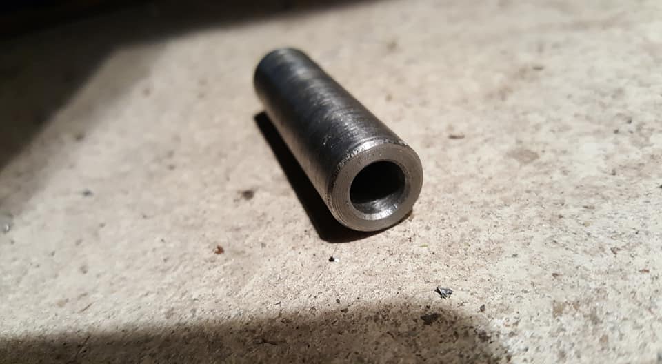
the hole it goes in
i greased it up because it will move around slightly which is why the shifter was so tight, i didnt think it would really need to but i guess it rotates slightly.
and here the linkage is installed. i still need to make some washers to take up the space between the linkage and the transmission fork thing but the shifter is a million times better now.

i also installed my wideband, i didnt take many pictures of this, all i really did was drill a hole in the exhaust tunnel and wrap the cable in some pieces of hose and cram it into the hole and then i rolled up the excess and stashed it under my center console. i still need to mount this giant plug under the car somehow (ill probably make a bracket i can zip tie it to)

and heres a video of the wideband working.
https://www.youtube.com/watch?v=S86d...ature=youtu.be
so after i got the car running and began to try and tune a little bit i realized i couldnt really get the car to idle how i wanted. it seemed a little erratic and ive suspected for a while it was down a cylinder from it sounding like it was cammed this whole time, one of the injectors has a little retention nub worn off of it and wouldnt you know it but thats the one that isnt firing. its not the plug being loose because i pulled it off and pushed it on several times and it changed nothing so the injector must be stuck. next time im there im going to see if i can tap on it a few times to get it unstuck but if it wont go ill have to go to the junkyard and grab another one. hopefully i can find one thats the same size, if not i might just make a new fuel rail and run my bosch 550s off of the z since i know they are good and i probably wont run them in my z anyway.
tomorrow im going to be bringing my honda civic hybrid daily to the shop to replace the input shaft bearing, idk if i said that it was the throwout bearing earlier but i definitely thought it was the input shaft bearing and someone talked me into thinking it was the throwout bearing until i looked it up and found a service bullitin proving that i was right in the first place so i can post some pics of that when i pull the transmission out and apart if anyone is interested. after that is done ill probably grab some more argon and finish my catch can finally and then the stanza will be ready for some tuning and possibly a test drive. we will see.
heres the pin
the hole it goes in
i greased it up because it will move around slightly which is why the shifter was so tight, i didnt think it would really need to but i guess it rotates slightly.
and here the linkage is installed. i still need to make some washers to take up the space between the linkage and the transmission fork thing but the shifter is a million times better now.
i also installed my wideband, i didnt take many pictures of this, all i really did was drill a hole in the exhaust tunnel and wrap the cable in some pieces of hose and cram it into the hole and then i rolled up the excess and stashed it under my center console. i still need to mount this giant plug under the car somehow (ill probably make a bracket i can zip tie it to)
and heres a video of the wideband working.
https://www.youtube.com/watch?v=S86d...ature=youtu.be
so after i got the car running and began to try and tune a little bit i realized i couldnt really get the car to idle how i wanted. it seemed a little erratic and ive suspected for a while it was down a cylinder from it sounding like it was cammed this whole time, one of the injectors has a little retention nub worn off of it and wouldnt you know it but thats the one that isnt firing. its not the plug being loose because i pulled it off and pushed it on several times and it changed nothing so the injector must be stuck. next time im there im going to see if i can tap on it a few times to get it unstuck but if it wont go ill have to go to the junkyard and grab another one. hopefully i can find one thats the same size, if not i might just make a new fuel rail and run my bosch 550s off of the z since i know they are good and i probably wont run them in my z anyway.
tomorrow im going to be bringing my honda civic hybrid daily to the shop to replace the input shaft bearing, idk if i said that it was the throwout bearing earlier but i definitely thought it was the input shaft bearing and someone talked me into thinking it was the throwout bearing until i looked it up and found a service bullitin proving that i was right in the first place so i can post some pics of that when i pull the transmission out and apart if anyone is interested. after that is done ill probably grab some more argon and finish my catch can finally and then the stanza will be ready for some tuning and possibly a test drive. we will see.
05-18-2018, 02:16 PM
#315
I have some concerns about the wideband cable by the exhaust pipe. It gets real hot around the pipe and I wonder it the heat will harm the wires and/or connector. One thing car makers do is put a heat shield in to protect anything close to the pipe. Maybe you should consider a heat shield if there is room.
05-20-2018, 11:12 PM
#316
Member
Thread Starter
Join Date: Oct 2016
Posts: 284
I have some concerns about the wideband cable by the exhaust pipe. It gets real hot around the pipe and I wonder it the heat will harm the wires and/or connector. One thing car makers do is put a heat shield in to protect anything close to the pipe. Maybe you should consider a heat shield if there is room.
05-23-2018, 11:30 AM
#317
Sorry if I didn't make myself clear. I know you would not leave the wire loose to flop around, you don't do that kind of sloppy work.
What I am suggesting is a piece of sheet metal between the exhaust pipe and the wire like car makers use at various places along the exhaust system. They do help protect things like wires.
What I am suggesting is a piece of sheet metal between the exhaust pipe and the wire like car makers use at various places along the exhaust system. They do help protect things like wires.
05-23-2018, 09:12 PM
#318
Member
Thread Starter
Join Date: Oct 2016
Posts: 284
Sorry if I didn't make myself clear. I know you would not leave the wire loose to flop around, you don't do that kind of sloppy work.
What I am suggesting is a piece of sheet metal between the exhaust pipe and the wire like car makers use at various places along the exhaust system. They do help protect things like wires.
What I am suggesting is a piece of sheet metal between the exhaust pipe and the wire like car makers use at various places along the exhaust system. They do help protect things like wires.
05-23-2018, 10:51 PM
#319
Member
Thread Starter
Join Date: Oct 2016
Posts: 284
alright i just finished fixing the hybrid last night, probably put a good 30 hours into the whole job, i know its been a whole week but i only was able to actually get a ride over to my garage 3 times lol. i took some pics and video along the way so for anyone whos interested heres what that was all about.
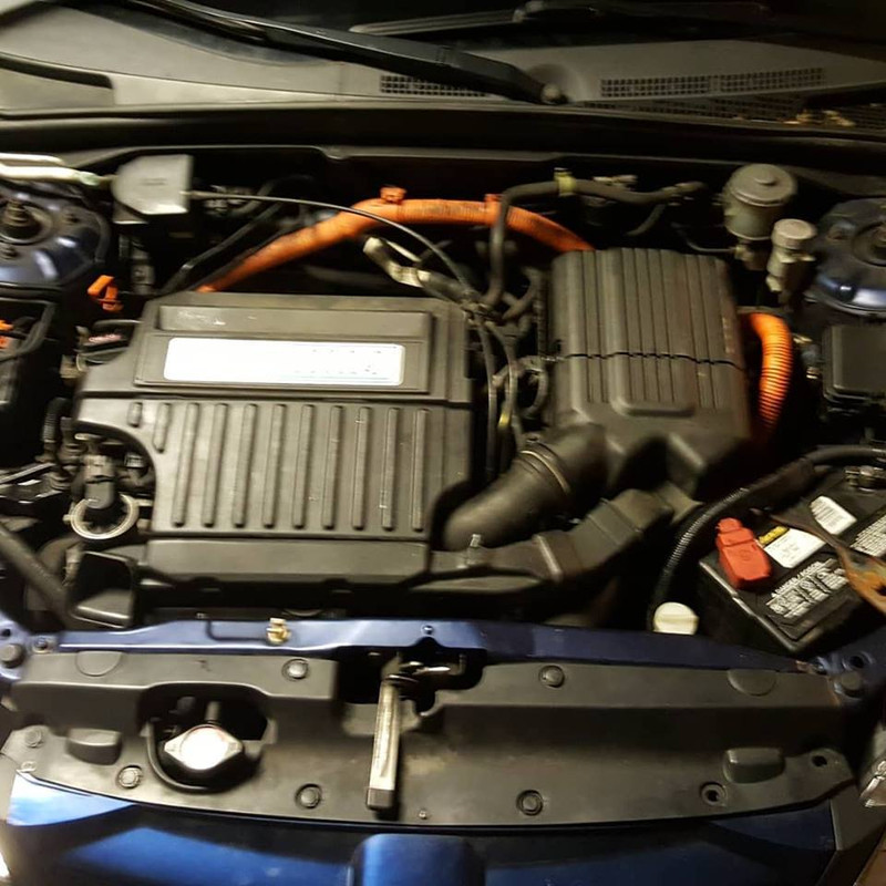
here is what the engine bay looks like, i actually took this pic when i was finished but since this car is going to remain stock forever i put literally everything back in exactly the way it came out. (not one left over part or bolt)
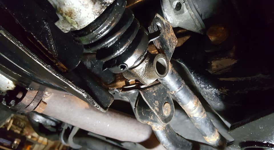
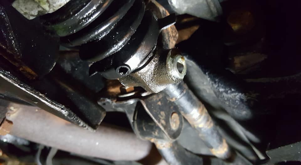
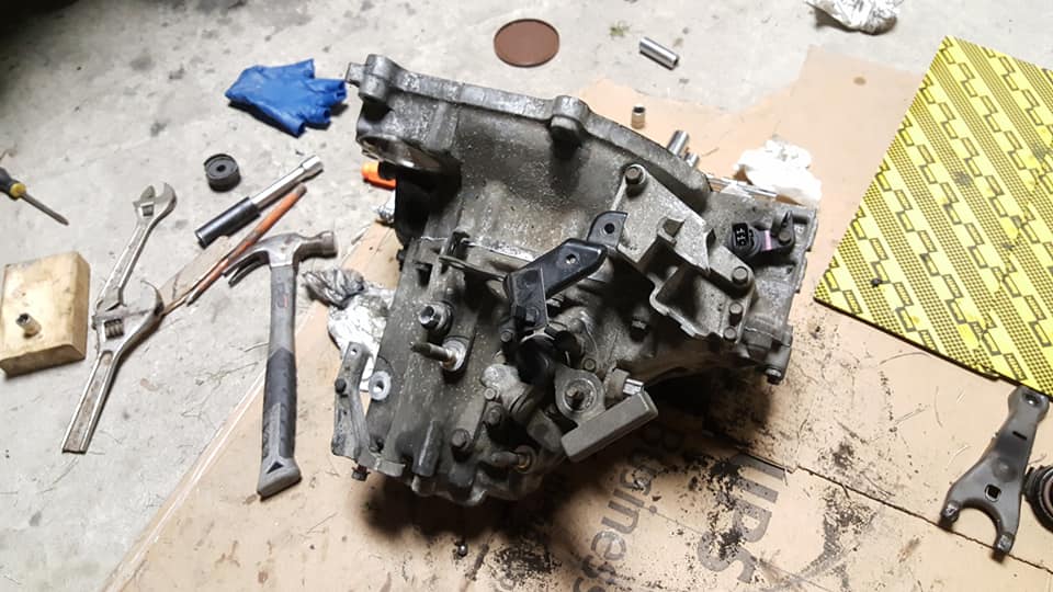
heres the trans halfway out, i didnt really have to pull too much out from the top besides the intake and some brackets, shift linkages and stuff like that. i did however have to drop the subframe and support the engine because i didnt want to take off anything i didnt absolutely have to.
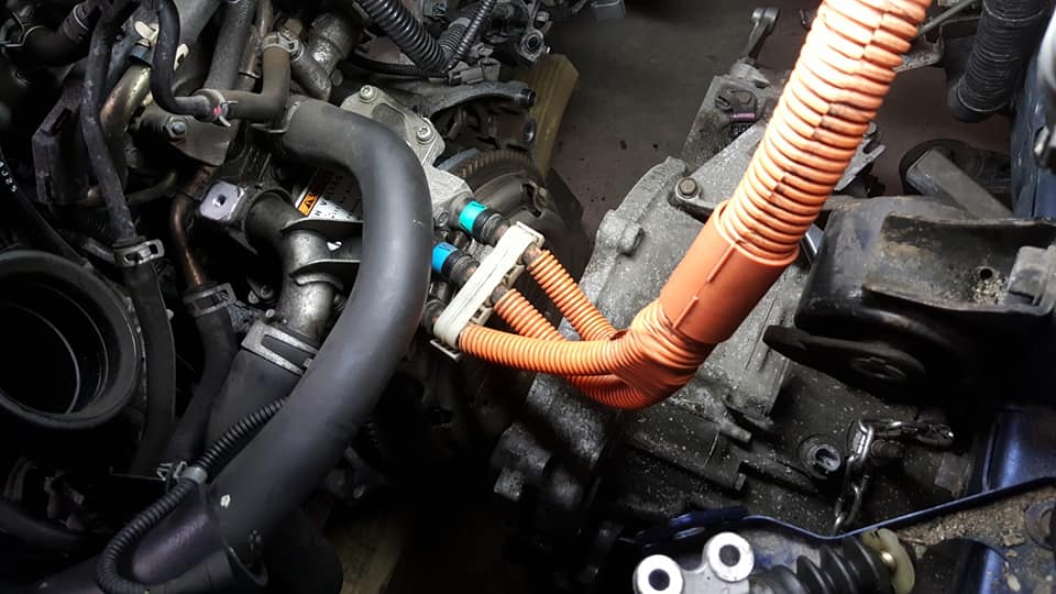
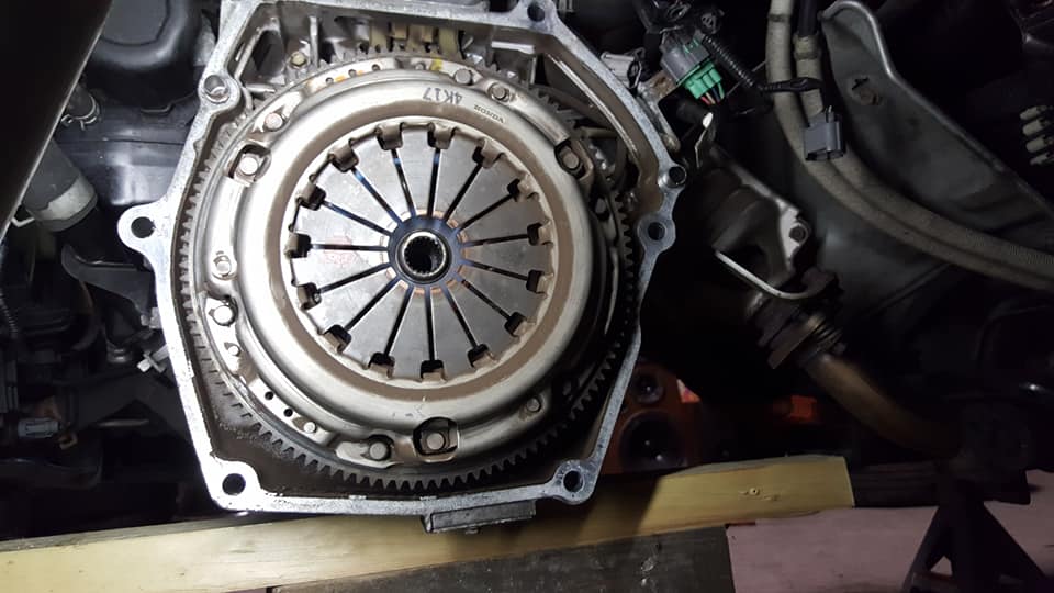
here is the clutch. you cant really see the electric motor from here but its between the crank and the flywheel so im assuming it acts as a sort of one way clutch that can only add torque, otherwise if it could spin in both directions the engine would spin without turning the flywheel. i find it very interesting but im also extremely glad that i didnt have to mess with any of it since pulling the trans didnt require any extra steps at all. and just in case you were wondering no i didnt do the clutch. i pulled it off and made sure it wasnt on the verge of exploding and it looked halfway decent so it stayed.
case off of the transmission
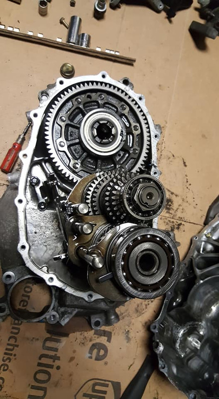
i took a few videos to show just how bad the bearing was, the plastic cage exploded and was deposited throughout the transmission and there were metal shavings everywhere but aside from that the gear set and other bearings looked perfect. no noticeable wear or damage anywhere at all which i was very happy about. this video basically just shows the amount of play the input shaft had which is why when the car was running it sounded like a blender full of silverware was running on high and then once i get inside the trans the state of the bearing and the new bearing after it was installed.
https://www.youtube.com/watch?v=U2Ko...ature=youtu.be
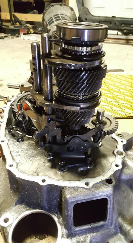
here is the reassembled trans. this is the first time i have ever actually opened a transmission in my life and honestly it was not as difficult as i expected it to be. there are little things you absolutely cant do otherwise you will really mess your trans up but if youre careful and watch a tutorial like i did that explains clearly what you need to do then really anyone can do this with a laymans understanding of mechanics. its intimidating at first but really so is everything else when you havent done it before.
anyway thats all for the hybrid, i drove it home and everything was so quiet i could hear the relays for the windshield wipers clicking lol very satisfying. ill be back to the normal scheduled programming very soon. first thing getting my attention is that stuck injector which i did check and it isnt ohmed out so it is definitely just stuck, hopefully i can get it unstuck.
here is what the engine bay looks like, i actually took this pic when i was finished but since this car is going to remain stock forever i put literally everything back in exactly the way it came out. (not one left over part or bolt)
heres the trans halfway out, i didnt really have to pull too much out from the top besides the intake and some brackets, shift linkages and stuff like that. i did however have to drop the subframe and support the engine because i didnt want to take off anything i didnt absolutely have to.
here is the clutch. you cant really see the electric motor from here but its between the crank and the flywheel so im assuming it acts as a sort of one way clutch that can only add torque, otherwise if it could spin in both directions the engine would spin without turning the flywheel. i find it very interesting but im also extremely glad that i didnt have to mess with any of it since pulling the trans didnt require any extra steps at all. and just in case you were wondering no i didnt do the clutch. i pulled it off and made sure it wasnt on the verge of exploding and it looked halfway decent so it stayed.
case off of the transmission
i took a few videos to show just how bad the bearing was, the plastic cage exploded and was deposited throughout the transmission and there were metal shavings everywhere but aside from that the gear set and other bearings looked perfect. no noticeable wear or damage anywhere at all which i was very happy about. this video basically just shows the amount of play the input shaft had which is why when the car was running it sounded like a blender full of silverware was running on high and then once i get inside the trans the state of the bearing and the new bearing after it was installed.
https://www.youtube.com/watch?v=U2Ko...ature=youtu.be
here is the reassembled trans. this is the first time i have ever actually opened a transmission in my life and honestly it was not as difficult as i expected it to be. there are little things you absolutely cant do otherwise you will really mess your trans up but if youre careful and watch a tutorial like i did that explains clearly what you need to do then really anyone can do this with a laymans understanding of mechanics. its intimidating at first but really so is everything else when you havent done it before.
anyway thats all for the hybrid, i drove it home and everything was so quiet i could hear the relays for the windshield wipers clicking lol very satisfying. ill be back to the normal scheduled programming very soon. first thing getting my attention is that stuck injector which i did check and it isnt ohmed out so it is definitely just stuck, hopefully i can get it unstuck.