
So...who wants a gear indicator in the cluster?


Maxtank,
You are making it harder than necessary.
Here is how I would go about it. Use the orange indicator in the shifter as a bridge for each connection. As it moves up and down along a pathway, have it disconnect one circuit, and connect another. Like this:
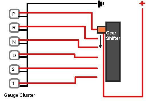
So as it moves from the P position, it breaks that circuit, turning off the bulb. Whatever gear it goes in next, the circuit would complete.
You are making it harder than necessary.
Here is how I would go about it. Use the orange indicator in the shifter as a bridge for each connection. As it moves up and down along a pathway, have it disconnect one circuit, and connect another. Like this:
So as it moves from the P position, it breaks that circuit, turning off the bulb. Whatever gear it goes in next, the circuit would complete.
to tell you the truth, i don't think its worth it for the amount of time and effort you would have to put in for couple of displays.

The only reasons I would do it is if a) I am going to keep the auto after my build and b) I can source a cluter with the indicators.
That way, I can just use the 'push' style shifting, with a leather boot instead of the button.
That way, I can just use the 'push' style shifting, with a leather boot instead of the button.


No, it's not useless if you wanted to do the manumatic mod.
I tried this myself a couple of months back on an extra cluster I have, but didn't really get anywhere with it. Interested to see if anyone figures out a way to do it.
I tried this myself a couple of months back on an extra cluster I have, but didn't really get anywhere with it. Interested to see if anyone figures out a way to do it.

as far as i know, only 1 person was able to do it and it was crap.
Im working on an n/a build this fall. Pm me if you wanna know more. Lets just say Ive got high, high hopes. 
Also, this is useful for those who want to do what The Wizard(I think) did, switching to a different, manual style shifter and boot. Looks a hell of a lot better, classier and its cool.
Also, this is useful for those who want to do what The Wizard(I think) did, switching to a different, manual style shifter and boot. Looks a hell of a lot better, classier and its cool.

I thought the same thing. Thisis something that really gotta see if it finishes
Im working on an n/a build this fall. Pm me if you wanna know more. Lets just say Ive got high, high hopes.
Also, this is useful for those who want to do what The Wizard(I think) did, switching to a different, manual style shifter and boot. Looks a hell of a lot better, classier and its cool.
Also, this is useful for those who want to do what The Wizard(I think) did, switching to a different, manual style shifter and boot. Looks a hell of a lot better, classier and its cool.
what are you changing out the internals, port/polish, bore, etc for drag or something? n/a build is a hell of a lot of work and A LOT more money than simply FI. but more power to yah.
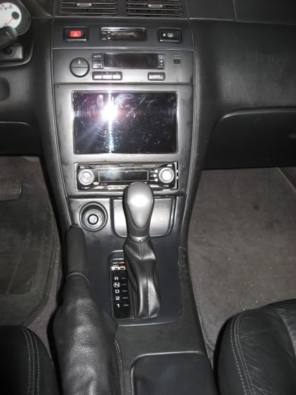
manual style shifter and boot as to something like this?: (not my pic)
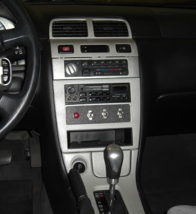
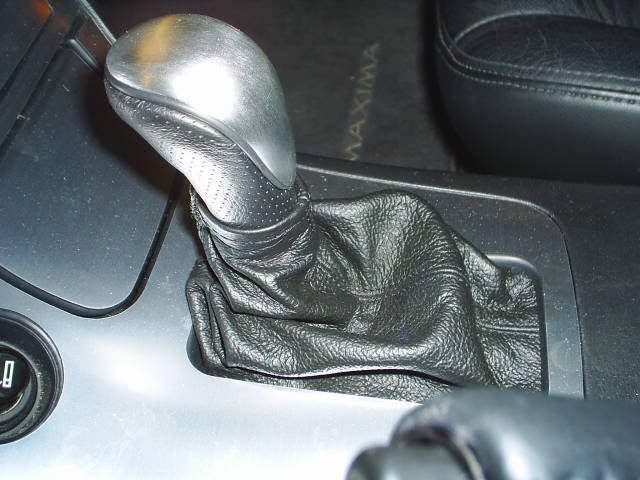
i have the same setup except the boot which i'm working on making one right now:

Maxtank,
You are making it harder than necessary.
Here is how I would go about it. Use the orange indicator in the shifter as a bridge for each connection. As it moves up and down along a pathway, have it disconnect one circuit, and connect another. Like this:
So as it moves from the P position, it breaks that circuit, turning off the bulb. Whatever gear it goes in next, the circuit would complete.
The A32 already has the switch for the cluster on the transmission. You just need to tap into it. Check your FSM schematics. I believe it is called the inhibitor switch. Tells the TCM what gear you have physically selected.
It's not that difficult to get the AT indicator working, or even swap in a different cluster. I would not go out of my way for a Y33 cluster, when you could have an I30/35 fluorescent cluster:


Last edited by made in china; Oct 19, 2009 at 08:05 PM.
^^^ the I30/35 fluorescent cluster would only be compatible for those with digital clusters correct? was it just a simple plug and play? oh wait, i see that your 3.5 swapped...  also since you have the 04 at, can you get a shifter trim that has PRND321 so it'll match your cluster?
also since you have the 04 at, can you get a shifter trim that has PRND321 so it'll match your cluster?
Last edited by G4nismo; May 22, 2008 at 08:12 PM.
^^^ the I30/35 fluorescent cluster would only be compatible for those with digital clusters correct? was it just a simple plug and play? oh wait, i see that your 3.5 swapped... also since you have the 04 at, can you get a shifter trim that has PRND321 so it'll match your cluster?
also since you have the 04 at, can you get a shifter trim that has PRND321 so it'll match your cluster?I35 cluster should be compatible with 02+ Maxima's. The reasoning is because of the type of CAN system these cars use. The 02+ has a trip computer that is part of the A33B CAN system.
My car is a 97, and since I have a full swap, this cluster is basically a match for the harness I put in the car.
I probably could put the gated PRND321 shifter in. I should check. I already tried putting the I35 center console in, and everything lined up...so yeah good idea g4, I'll check into it.
Currently my O/D switch activates "3".


From this thread. http://forums.maxima.org/showthread....9384&highlight= He called it a manumatic. Automatic made to look like manual.

I thought we were talking about this manumatic:
http://www.vqpower.com/v2/infusions/...?article_id=80
http://www.vqpower.com/v2/infusions/...?article_id=80
He forgot to mention who is helping him and doing an engine build right along with him. My theory has always been build the engine then FI, mainly because the power gains and end result will put a bigger smile on your face.
g4nismo, Check your pms.
coachholland, That was the thread I was referring to. Credit to ptatohed. If you did what he did with the shifter, it makes it look a LOT better, more sporty and modern. This is where the in-dash indicator would be helpful.
coachholland, That was the thread I was referring to. Credit to ptatohed. If you did what he did with the shifter, it makes it look a LOT better, more sporty and modern. This is where the in-dash indicator would be helpful.
I put a ES300 cluster in my MT Solara this way. Works perfect.
You can kind of see the tape on the PRND123 between the tach and speedo.


As you can see, I like to change the clusters in my cars.
Is this example for the AT cars?
The A32 already has the switch for the cluster on the transmission. You just need to tap into it. Check your FSM schematics. I believe it is called the inhibitor switch. Tells the TCM what gear you have physically selected.
It's not that difficult to get the AT indicator working, or even swap in a different cluster. I would not go out of my way for a Y33 cluster, when you could have an I30/35 fluorescent cluster:
 Jordan from New Zealand was nice enough to track down an Australian PRND cluster for me. The Wiz and I have actually installed it in my car already but it wasn't plug and play like we hoped.
  So, next is the wiring dilemma.
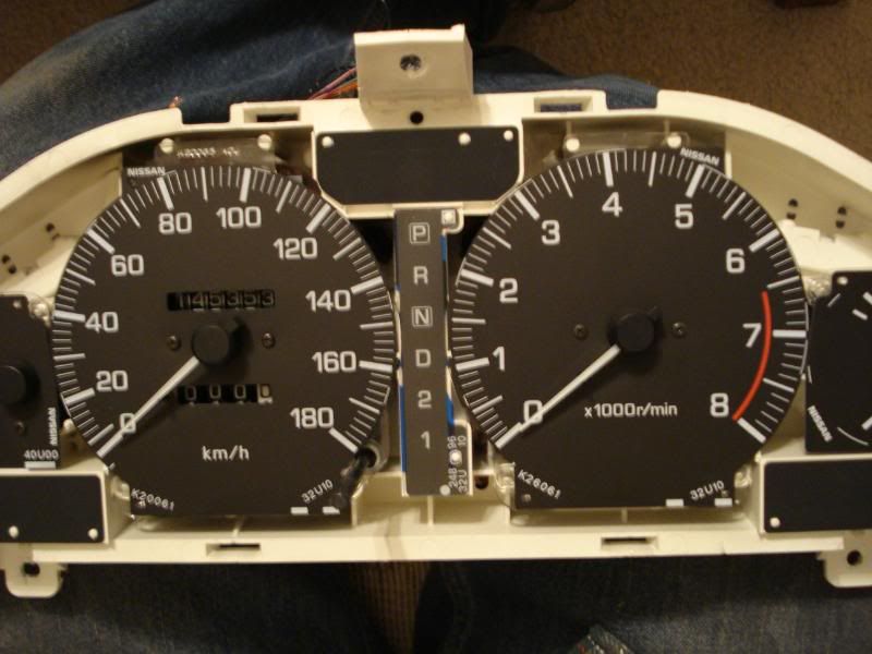
My OEM cluster:
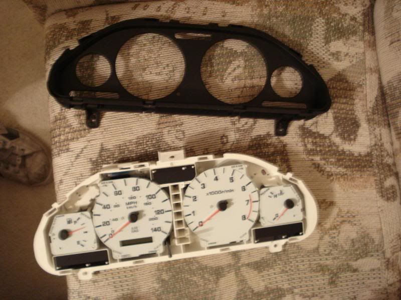
The AU cluster:
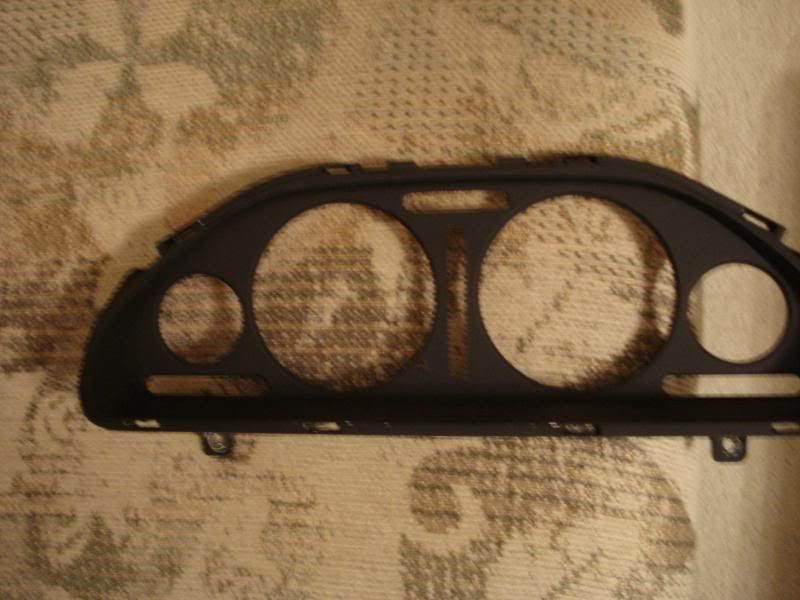
The AU bezel:
Like The Wiz said, we are almost there in adding the PRND to my '99 U.S. SE! Jordan from New Zealand was nice enough to track down an Australian PRND cluster for me. The Wiz and I have actually installed it in my car already but it wasn't plug and play like we hoped. So, next is the wiring dilemma.
Jordan from New Zealand was nice enough to track down an Australian PRND cluster for me. The Wiz and I have actually installed it in my car already but it wasn't plug and play like we hoped. So, next is the wiring dilemma.What color bulbs does the aus cluster have for the gear indicator?
You have the hard part done now with having the indicator and bezel.
What did it cost you?
It's probably plug-n-play for 95-97 clusters. The gear indicator wouldn't work though since are harness doesn't have any wires in the correct pins.
What color bulbs does the aus cluster have for the gear indicator?
You have the hard part done now with having the indicator and bezel.
What did it cost you?
What color bulbs does the aus cluster have for the gear indicator?
You have the hard part done now with having the indicator and bezel.
What did it cost you?
The bulbs are just white, like all other bulbs. It's the PRND overlay which is colored. The letters/numbers are colored green.
It cost me money! Oh, you mean, how much did it cost me!
 The shipping killed me but I think after everything it was still only around $70 U.S.
 I'll keep you guys updated on the progress.
Our.
The bulbs are just white, like all other bulbs. It's the PRND overlay which is colored. The letters/numbers are colored green.
It cost me money! Oh, you mean, how much did it cost me! The shipping killed me but I think after everything it was still only around $70 U.S.
I'll keep you guys updated on the progress.
The bulbs are just white, like all other bulbs. It's the PRND overlay which is colored. The letters/numbers are colored green.
It cost me money! Oh, you mean, how much did it cost me!
The shipping killed me but I think after everything it was still only around $70 U.S. I'll keep you guys updated on the progress.
Can the green part be removed?
$70 isn't that bad. Did you ever try to get the gear indicator or bezel from an aus dealer?
Do they still have a gear indicator on there shifter?
Ha Ha. You're right. I had to rephrase that a few times and it's past my bed time tonight.
Can the green part be removed?
$70 isn't that bad. Did you ever try to get the gear indicator or bezel from an aus dealer?
Do they still have a gear indicator on there shifter?
Can the green part be removed?
$70 isn't that bad. Did you ever try to get the gear indicator or bezel from an aus dealer?
Do they still have a gear indicator on there shifter?
Yeah, the green is just an overlay. It pops right off the AU cluster and transfers to the US cluster just fine. We have the little pegs and everything.
Dealer? No. But some of the junk yards over there wanted $300+! I am very grateful to Jordan and the other guys for helping me out. I posted on the Maxima down under forum on the wanted to buy section and they helped me out. They found it on a local ebay-like auction site.
Yes, they still have the floor indicator.
ugh do i have to pm you?
what are you changing out the internals, port/polish, bore, etc for drag or something? n/a build is a hell of a lot of work and A LOT more money than simply FI. but more power to yah.
manual style shifter and boot as to something like this?: (not my pic)
i have the same setup except the boot which i'm working on making one right now:
PRND21 in the gauge cluster
I definitley find myself in the same dilemma, I installed my shift boot and converted a nice Momo shift **** stated for Manuel Use Only and made it work for my automatic. It sucks not to be able to see what gear your in. I mean not that I can't feel the difference between being in 2 and D but it would be convienient to have a display in the gauge cluster. I don't like the look someone did leaving the shift boot not covering the display, but to each thier own.
I was thinking of cutting a slot in shift boot near the display and adding a small piece of plexi glass to view the display, but I really don't want to cut into my nice Redline $70 shift boot. Ptaoehed I would like one of the displays you have from New Zealand, could you direct me where to get one? Once I start looking into the wiring I'll see what I can rig up. Basically it would be a set of contacts that work with the moving plastic with orange indicator. Each time you move the shifter it comes in contact with each individual light bulb circuit lighting each bulb PRND21 as you change gears. This is like someone else suggested earlier in the thread. I would love to know if anyone has made any progress on this.
I was thinking of cutting a slot in shift boot near the display and adding a small piece of plexi glass to view the display, but I really don't want to cut into my nice Redline $70 shift boot. Ptaoehed I would like one of the displays you have from New Zealand, could you direct me where to get one? Once I start looking into the wiring I'll see what I can rig up. Basically it would be a set of contacts that work with the moving plastic with orange indicator. Each time you move the shifter it comes in contact with each individual light bulb circuit lighting each bulb PRND21 as you change gears. This is like someone else suggested earlier in the thread. I would love to know if anyone has made any progress on this.
Last edited by maxprivate; Oct 12, 2009 at 06:57 PM.


i think ima start on that wiring diagram he gave us to use.. shouldn't be too hard.. i'll get on it this weekend. But the only thing that will possible suck is the Wiring.. the LED's won't be a problem.. since my car is blue, i can just buy the Blue, 12 Volt LED's from autozone or something like that and solder them in place of the display. and use them for lighting, since it already has resistors and such.. but the other wiring.. hmm... maybe I can just use like a really small guage wire. o_O but thats an idea, but i'll get on it this weekend. shouldn't be tooooo hard
i think ima start on that wiring diagram he gave us to use.. shouldn't be too hard.. i'll get on it this weekend. But the only thing that will possible suck is the Wiring.. the LED's won't be a problem.. since my car is blue, i can just buy the Blue, 12 Volt LED's from autozone or something like that and solder them in place of the display. and use them for lighting, since it already has resistors and such.. but the other wiring.. hmm... maybe I can just use like a really small guage wire. o_O but thats an idea, but i'll get on it this weekend. shouldn't be tooooo hard
Im guessing those bulbs run at 5v? I would much rather do it that way rather than trying to solder LED's on each one of the spots on the back of the cluster. Just my opinion though.
Last edited by maxprivate; Oct 13, 2009 at 02:03 PM.
The problem is going to be finding a way to make a circuit that will work with the shifter ie, sending power to each individual bulb depending on the gear your in. As for soldering a LED in the PRND21 spots in the back of the cluster, I thought there was no power there. Or are your saying you will bring 12v source to each bulb depending on the gear your in? Im going to try and use the bulb housing that are suppsed to be the PRND21 spots in the back of the cluster.
Im guessing those bulbs run at 5v? I would much rather do it that way rather than trying to solder LED's on each one of the spots on the back of the cluster. Just my opinion though.
Im guessing those bulbs run at 5v? I would much rather do it that way rather than trying to solder LED's on each one of the spots on the back of the cluster. Just my opinion though.
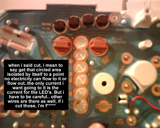
well, ima take a razor and cut connections to the printed part for where the PRND "sockets" would be that way, if for any reason that i apply voltage and something backfires on that circuit, i won't have the whole circuit go bad.. so thats just incase... i aint gonna use 2nd or 1.. so lighting them would be useless. But besides that. as i was saying, i would go through the trouble of sodering in the LED's in place of the PRND display, since the LED's at advanced auto parts, (autozone had none) were like almost 10 bucks for 4.. -_-.. but anyway. soldering them into the display aint a problem. the only "real" problem, like you said, is using the shifter as a switch. Because the bolt on that shifter would be a GREAT thing to mount the wire. But the only problem is, that shifter moves that bolt kind in a curve downwards.. i just gotta figure out how to get or actually make some kind of board to place there where the shifter can pass over it and still make a "good" contact with the rest of the wires and complete a circuit. But i'm still pondering on this. so give me some time..
my other idea is. Instead of the word lighting up to what gear you are in, i was thinking about getting an LED strip and go ahead and have the letters lit up in the background, and have the LED on the side of the letter to indicate what gear you are in. It's kind of a similar idea with my GS300 cluster. instead, the cluster itself lights up everything.. so i don't know. I'll think of something. unless someone comes up to me with a better idea.
What I would do is make the shifter a ground switching circuit. Send ALL of the LED's their 12 V, but make each of them have a ground that runs to different spots on the shifter. When the in park, the P led ground is connected, and so forth for each ones. Makes much more sense, and is easier that way.
What I would do is make the shifter a ground switching circuit. Send ALL of the LED's their 12 V, but make each of them have a ground that runs to different spots on the shifter. When the in park, the P led ground is connected, and so forth for each ones. Makes much more sense, and is easier that way.
Last edited by maxprivate; Oct 15, 2009 at 05:14 AM.
You don't have to cut out the whole area of PRND21, you can just notch out the area where the contacts of the bulb holder may have contact with. That's why when I do mine I'm going to use the Bulb holders with regular bulbs (forgot the size I know those are smaller than 194 I believe) rather than solder leds in place. Then mod the power feed in the buld holders. I think its easier that way.
Last edited by maxprivate; Jun 20, 2010 at 08:27 PM.
I agree using it as a ground is a great idea but the problem still remains of how you would complete each ground when shifting gears to each corresponding light. I thought of using a terminal block with 6 poles one for each PRND21 it can be mounted under the current display plenty of room there. But again how to connect some type of device to the shifter to have it come in contact with each circuit when changing gears is the problem. It would have to be something totally custom. I wonder how Ptatohed made out with his.. Its been over a year and no update.
You don't have to cut out the whole area of PRND21, you can just notch out the area where the contacts of the buld holder may have contact with. That's why when I do mine I'm going to use the Bulb holders with regular bulbs (forgot the size I know those are smaller than 194 I believe) rather than solder leds in place. Then mod the power feed in the buld holders. I think its easier that way.
Ill take a look at it for you sometime this weekend and see if I cant fab something up.
Once I get a hold of the NZ Cefiro cluster I'll start this project it shouldn't be to back since I already have an idea of what needs to be done.
No need to "isolate" that circle, or anything. The traces that are inside that red circle have no continuity to anywhere else on the board. I.E. The'yre already isolated.
