
Manumatic and shift kit


Manumatic and shift kit
I saw in the how-to's that there is a manumatic setup that IS NOT the suprastick setup where there is a "manumatic control box", an led screen, a number of wires, and it is controlled with the cruise control buttons. All of the links in every thread were dead and gone and I am left in between knowing and buying the setup. Anyone have ANY extra information on this?
I'm in the same spot with a shift kit. I've heard of numerous different setups for a shift kit that were not the trans-go kit and did not require you to change springs and whatnot. Only "Valve body mods". Again I couldn't find any links or information that was actually up-to-date and useful. I'm just looking for someone to point me in the right direction instead of leaving me wandering around the .org, vqpower, my4thgen, and random dsm forums for more weeks on weeks.
I'm in the same spot with a shift kit. I've heard of numerous different setups for a shift kit that were not the trans-go kit and did not require you to change springs and whatnot. Only "Valve body mods". Again I couldn't find any links or information that was actually up-to-date and useful. I'm just looking for someone to point me in the right direction instead of leaving me wandering around the .org, vqpower, my4thgen, and random dsm forums for more weeks on weeks.
 .
. Lets see if anyone can shine some light on this matter.

Kit is discontinued but Jimes created one of his own and other have also.
http://forums.maxima.org/1-4-1-8-mil...orks-good.html
The links to the pics are working as well.
Hell if someone had the guts to covert the shifter to a 6thgen auto shifter with triptronic controls and use the suprastick piggy back system to work off it then that would be even better, but a lot of modifications is needed to do something like that unless you swapped the transmission and the TCM from the 6thgen. Lots of ideas but limited options.
The Fast Mod
http://forums.maxima.org/all-motor/3...-fast-mod.html
And the Vqpower one is the last one, Im sure you've seen all of these. Buts that pretty much it. You just have to read up on it and maybe make your own modifications to make it happen.
This is the info for the manumatic but like I said before that kit is discontinued.
** DIY disclaimer: I am in no way, shape, or form, responsible for any damage (to the car, part, wiring or your person) that may occur in the process of completing this mod. **
Source Credit: VQPOWER
Written by Rob
1. General Overview
If you can install a car alarm, you can install this kit. However, if you make a mistake, it may render your car undriveable. Please take your time and following all the test procedures listed in the installation guide.
Disclaimer: Because this is a do it yourself modification, I will not be responsible for either the INSTALLATION, USE, or FUNCTION of this kit. Proceed with caution and at your own risk. This kit is for OFF-ROAD use only.
1.1 Kit Contents
The kit includes:
* A. Manumatic Controller Box
* B. Power Cable
* C. Control Cable (7 ft)
* D. Relay Module
* E. Remote LED Display and Cable (optional, 7ft)

Figure 1. Kit Contents
1.2 Equipment Needed
* philips screwdriver
* wire cutter / wire stripper
* electrical tape
* solder gun and solder
* double sided tape
You must solder all wire connections for solid contacts.
1.3 Connector Locations
There are only 2 areas of the car where we need to perform wire cutting and splicing.
The first area is the ASCD Connector (M30). The ASCD connector is out in the open, located near the driver's right knee (shown below).

Figure 2. ASCD Connector
The second area is the TCM Connectors. For the 1998-1999 Maxima, there are 2 TCM Connectors (F109 and F108, shown in Figure 3a below). The TCM Connectors are accessible by removing the ashtray assembly. F109 is on the left and F108 is on the right.
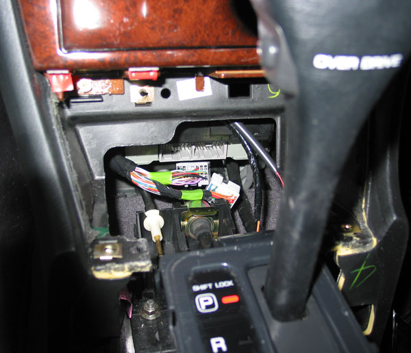
Figure 3a. TCM Connectors in 1998-1999 Maxima (F109 on left, F108 on right)
For the 1995-1997 Maxima, there is only 1 TCM Connector (protected by a bolt shown in Figure 3b below). The TCM Connector is accessible by removing the ashtray assembly. Thanks go to Eric W. for tracking down the following images and diagrams.

Figure 3b. TCM Connector in 1995-1997 Maxima
1.4 Kit Layout
The following diagram shows the recommend layout of the kit's components.
Figure 4. Kit Layout
The Manumatic Controller Box is placed under the driver's seat. The Relay Module is taped to the inside of the dash. Where to put the optional "Remote LED Display" is left up to you.
1.5 Wire Colors
The following table shows color codes used to represent different wire colors.
B = Black
W = White
R = Red
G = Green
L = Blue
Y = Yellow
G = Light Green
BR = Brown
OR = Orange
P = Pink
PU = Purple
GY = Gray
Figure 5. Wire Colors
When the wire color is striped, the base color is given first, followed by the stripe color as shown below:
Example: L/W = Blue with White Stripe
1.6 Wire Modifications
We will be making wire connections in 2 different ways: tapping and highjacking.
Tapping a wire involves the addition of a new wire to an existing wire. The existing wire must NOT be cut. The following diagram shows a before and after picture.

Figure 6. Tapping an Existing Wire
Highjacking a wire involves the cutting of the existing wire and attaching 2 new wires to the cut ends. The following diagram shows a before and after picture.

Figure 7. Highjacking an Existing Wire
2.0 Installation
The installation should take you one day. The instructions will start by asking you to remove/loosen interior trim pieces to bring the work areas into view. Try to get to know where the wires and components will go before installing anything. During the installation, there will be tests which you should run to help verify proper installation. Install the Remote LED Display last in case you run out of daylight (since it's optional).
2.1 Accessing the TCM Connectors
Start by removing the shifter trim and then the ashtray assembly (shown in figure below).

Figure 8. Dash Trim Removal
Lift the shifter trim and then pull it towards you. Remove the power plug for the cigarette lighter and set the shifter trim aside. Remove the single screw holding the ashtray assembly in place. Pull the ashtray assembly out (it's now held in place by 1 clip on the right side). Remove the ashtray light plug and then set the ashtray aside.
The TCM should now be visible. Unplug the TCM connector(s) (see Figures 9a and 9b shown below). We will connect wires to these connectors later. If your hands are too big or if you are claustrophobic, then remove the stereo for more space to work in.

Figure 9. TCM Connectors in 1998-1999 Maxima (F109 on left, F108 on right)

Figure 9. TCM Connector in 1995-1997 Maxima
2.2 Loosen Center Console
You only need to loosen the center console to run the cables from under the driver's seat to the dash. Start by removing the top 2 screws on the center console (shown below).

Figure 10. Center Console Screws - Top Front
Next, remove the 2 screws in the back of the center console (1 on either side).

Figure 11. Center Console Screws - Bottom Rear
http://forums.maxima.org/1-4-1-8-mil...orks-good.html
The links to the pics are working as well.
Hell if someone had the guts to covert the shifter to a 6thgen auto shifter with triptronic controls and use the suprastick piggy back system to work off it then that would be even better, but a lot of modifications is needed to do something like that unless you swapped the transmission and the TCM from the 6thgen. Lots of ideas but limited options.
The Fast Mod
http://forums.maxima.org/all-motor/3...-fast-mod.html
And the Vqpower one is the last one, Im sure you've seen all of these. Buts that pretty much it. You just have to read up on it and maybe make your own modifications to make it happen.
This is the info for the manumatic but like I said before that kit is discontinued.
** DIY disclaimer: I am in no way, shape, or form, responsible for any damage (to the car, part, wiring or your person) that may occur in the process of completing this mod. **
Source Credit: VQPOWER
Written by Rob
1. General Overview
If you can install a car alarm, you can install this kit. However, if you make a mistake, it may render your car undriveable. Please take your time and following all the test procedures listed in the installation guide.
Disclaimer: Because this is a do it yourself modification, I will not be responsible for either the INSTALLATION, USE, or FUNCTION of this kit. Proceed with caution and at your own risk. This kit is for OFF-ROAD use only.
1.1 Kit Contents
The kit includes:
* A. Manumatic Controller Box
* B. Power Cable
* C. Control Cable (7 ft)
* D. Relay Module
* E. Remote LED Display and Cable (optional, 7ft)
Figure 1. Kit Contents
1.2 Equipment Needed
* philips screwdriver
* wire cutter / wire stripper
* electrical tape
* solder gun and solder
* double sided tape
You must solder all wire connections for solid contacts.
1.3 Connector Locations
There are only 2 areas of the car where we need to perform wire cutting and splicing.
The first area is the ASCD Connector (M30). The ASCD connector is out in the open, located near the driver's right knee (shown below).
Figure 2. ASCD Connector
The second area is the TCM Connectors. For the 1998-1999 Maxima, there are 2 TCM Connectors (F109 and F108, shown in Figure 3a below). The TCM Connectors are accessible by removing the ashtray assembly. F109 is on the left and F108 is on the right.
Figure 3a. TCM Connectors in 1998-1999 Maxima (F109 on left, F108 on right)
For the 1995-1997 Maxima, there is only 1 TCM Connector (protected by a bolt shown in Figure 3b below). The TCM Connector is accessible by removing the ashtray assembly. Thanks go to Eric W. for tracking down the following images and diagrams.
Figure 3b. TCM Connector in 1995-1997 Maxima
1.4 Kit Layout
The following diagram shows the recommend layout of the kit's components.
Figure 4. Kit Layout
The Manumatic Controller Box is placed under the driver's seat. The Relay Module is taped to the inside of the dash. Where to put the optional "Remote LED Display" is left up to you.
1.5 Wire Colors
The following table shows color codes used to represent different wire colors.
B = Black
W = White
R = Red
G = Green
L = Blue
Y = Yellow
G = Light Green
BR = Brown
OR = Orange
P = Pink
PU = Purple
GY = Gray
Figure 5. Wire Colors
When the wire color is striped, the base color is given first, followed by the stripe color as shown below:
Example: L/W = Blue with White Stripe
1.6 Wire Modifications
We will be making wire connections in 2 different ways: tapping and highjacking.
Tapping a wire involves the addition of a new wire to an existing wire. The existing wire must NOT be cut. The following diagram shows a before and after picture.
Figure 6. Tapping an Existing Wire
Highjacking a wire involves the cutting of the existing wire and attaching 2 new wires to the cut ends. The following diagram shows a before and after picture.
Figure 7. Highjacking an Existing Wire
2.0 Installation
The installation should take you one day. The instructions will start by asking you to remove/loosen interior trim pieces to bring the work areas into view. Try to get to know where the wires and components will go before installing anything. During the installation, there will be tests which you should run to help verify proper installation. Install the Remote LED Display last in case you run out of daylight (since it's optional).
2.1 Accessing the TCM Connectors
Start by removing the shifter trim and then the ashtray assembly (shown in figure below).
Figure 8. Dash Trim Removal
Lift the shifter trim and then pull it towards you. Remove the power plug for the cigarette lighter and set the shifter trim aside. Remove the single screw holding the ashtray assembly in place. Pull the ashtray assembly out (it's now held in place by 1 clip on the right side). Remove the ashtray light plug and then set the ashtray aside.
The TCM should now be visible. Unplug the TCM connector(s) (see Figures 9a and 9b shown below). We will connect wires to these connectors later. If your hands are too big or if you are claustrophobic, then remove the stereo for more space to work in.
Figure 9. TCM Connectors in 1998-1999 Maxima (F109 on left, F108 on right)
Figure 9. TCM Connector in 1995-1997 Maxima
2.2 Loosen Center Console
You only need to loosen the center console to run the cables from under the driver's seat to the dash. Start by removing the top 2 screws on the center console (shown below).
Figure 10. Center Console Screws - Top Front
Next, remove the 2 screws in the back of the center console (1 on either side).
Figure 11. Center Console Screws - Bottom Rear
2.3 Install Cables
Try to visualize where all the wires and components will go before installing cables.
When you are ready to begin, locate the controller (yellow), display (blue), and power (red/black) cables (see Figure 1). Each cable should have a connector on one end and bare wires on the other end.
Start by placing the connector end of all 3 cables under the driver's seat. Route the cables under the seat rail into the center console. Tie the cables so that moving the seat does not cut the wires.

Figure 12. Put Cable Connectors Under Driver's Seat
Next, route the cables along the center console towards the dash (shown in the following 2 pictures). Tie the cables to the existing wires running along the center console.


Figure 13. Route Cables Through The Center Console Towards The Dash
The power cable ends in the dash where we will, later, connect it to the cigarette lighter.
Route the remote LED display cable (blue) through the dash and out the back of the dash (towards the gas pedal). We will mount the remote LED display last.
The controller cable (yellow) splits at the dash. Some wires will stay in the dash (for connection to TCM and relay module) while the rest will go through the back of the dash (for connection to ASCD).

Figure 14. Yellow Cable Split
Splitting from the yellow cable is a 3 pin connector. This will be connected to the relay module. Also splitting from the yellow cable are 2 wires (green, white/green) which will be connected to the TCM. Route the remainder of the yellow cable through the back of the dash. These wires will be connected to the ASCD control unit.
2.3 Connect ASCD Wires
The following diagram shows the ASCD connector, as-is. On this connector, we are only interested in 3 wires (pin 1 - Accel, pin 2 - Coast, pin 4 - Cruise). Make sure you identify the wires by both its color code and its relative location to other wires.

Figure 15. ASCD Connector Pinout
First, locate the green/orange "Accel" wire (pin 1 of ASCD connector). Next, locate the orange/white wire in the yellow control cable. We will tap into the "Accel" wire by connecting the orange/white wire to the green/orange wire (show below). Be sure to solder all connections together.

Figure 16. Modified ASCD Connector
In a similar fashion, we will tap into the "Coast" wire (pin 2 of ASCD connector) by connecting the orange wire from the control cable to the green/yellow wire.
Finally, tap into the "Cruise" wire (pin 4 of ASCD connector) by connecting the blue wire from the control cable to the green/white wire.
2.4 Connect Relay Module Wires
Start by unplugging the wires connected to the relay module (shown in figure below). We will connect these wires to the TCM. Later, we will plug the connector end back into the relay module.

Figure 17. Relay Module Wires
For 1998-1999 Maximas, follow the instructions in section 2.4.1. For 1995-1997 Maximas, follow the instructions in section 2.4.2.
2.4.1 Connect Relay Module Wires to 1998-1999 Maxima
The following diagram shows connector F109, as-is. On this connector, we are only interested in 3 wires (pin 26, 27, and 34). Make sure you identify the wires by both its color code and its relative location to other wires.

Figure 18. F109 Connector Pinout
Locate the Yellow/Blue wire on F109 (pin 34). Now locate the green wire and the yellow wire on the relay cable. We will highjack pin 34 with these 2 wires. Start by cutting the Yellow/Blue wire (pin 34). Connect the green wire to the half coming from the gearshifter. Connect the yellow wire to the half going towards the TCM (F109).

Figure 19. Modified F109 Connector
In a similar fashion, we will highjack pin 26 on F109 (Purple/White). Start by cutting the Purple/White pin 26 wire. Connect the brown wire to the half coming from the gearshifter. Connect the black wire to the half going towards the TCM (F109).
Lastly, highjack pin 27 on F109 (Pink/Black). Start by cutting the Pink/Black pin 27 wire. Connect the orange wire to the half coming from the gearshifter. Connect the red wire to the half going towards the TCM (F109).
2.4.2 Connect Relay Module Wires to 1995-1997 Maxima
The following diagram shows the TCM connector, as-is. For now, we are only interested in 3 wires (pin 16, 17, and 18). Make sure you identify the wires by both its color code and its relative location to other wires.

Figure 18. TCM Connector Pinout for 1995-1997 Maxima
Locate the Yellow/Blue wire (pin 18). Now locate the green wire and the yellow wire on the relay cable. We will highjack pin 18 with these 2 wires. Start by cutting the Yellow/Blue wire (pin 18). Connect the green wire to the half coming from the gearshifter. Connect the yellow wire to the half going towards the TCM.

Figure 19. Modified TCM Connector Pinout for 1995-1997 Maxima
In a similar fashion, we will highjack pin 16 (Purple/White). Start by cutting the Purple/White pin 16 wire. Connect the brown wire to the half coming from the gearshifter. Connect the black wire to the half going towards the TCM.
Lastly, highjack pin 17 (Pink/Black). Start by cutting the Pink/Black pin 17 wire. Connect the orange wire to the half coming from the gearshifter. Connect the red wire to the half going towards the TCM.
2.5 Connect Remaining TCM Wires
We only need 2 more wires on the TCM connector(s). For 1998-1999 Maximas, see section 2.5.1. For 1995-1997 Maximas, see section 2.5.2.
2.5.1 Connect Remaining TCM Wires on 1998-1999 Maxima
The following diagram shows the F108 connector, as-is. On this connector, we are only interested in 2 wires, pins 13 and 22. Make sure you identify the wires by both its color code and its relative location to other wires.

Figure 20. F108 Connector Pinout
First, locate pin 13 on F108 (White wire). Next, locate the Green/White wire from the yellow control cable. We will tap into the pin 13 by connecting the green/white wire to the white wire (show below).

Figure 21. Modified F108 Connector
In a similar fashion, we will tap into pin 22 on F108 (Green/Yellow) by connecting the green wire from the control cable to it. Be sure to solder all connections together.
2.5.2 Connect Remaining TCM Wires on 1995-1997 Maxima
The following diagram shows the next 2 wires on the TCM connector that we will be working on (pins 3 and 39). Make sure you identify the wires by both its color code and its relative location to other wires.

Figure 20. Original OD Wires on TCM Connector for 1995-1997 Maxima
First, locate pin 3 (White wire). Next, locate the Green/White wire from the yellow control cable. We will tap into the pin 13 by connecting the green/white wire to the white wire (show below).

Figure 21. Modified OD Wires on TCM Connector for 1995-1997 Maxima
In a similar fashion, we will tap into pin 39 (Green/Yellow) by connecting the green wire from the control cable to it. Be sure to solder all connections together.
Try to visualize where all the wires and components will go before installing cables.
When you are ready to begin, locate the controller (yellow), display (blue), and power (red/black) cables (see Figure 1). Each cable should have a connector on one end and bare wires on the other end.
Start by placing the connector end of all 3 cables under the driver's seat. Route the cables under the seat rail into the center console. Tie the cables so that moving the seat does not cut the wires.
Figure 12. Put Cable Connectors Under Driver's Seat
Next, route the cables along the center console towards the dash (shown in the following 2 pictures). Tie the cables to the existing wires running along the center console.
Figure 13. Route Cables Through The Center Console Towards The Dash
The power cable ends in the dash where we will, later, connect it to the cigarette lighter.
Route the remote LED display cable (blue) through the dash and out the back of the dash (towards the gas pedal). We will mount the remote LED display last.
The controller cable (yellow) splits at the dash. Some wires will stay in the dash (for connection to TCM and relay module) while the rest will go through the back of the dash (for connection to ASCD).
Figure 14. Yellow Cable Split
Splitting from the yellow cable is a 3 pin connector. This will be connected to the relay module. Also splitting from the yellow cable are 2 wires (green, white/green) which will be connected to the TCM. Route the remainder of the yellow cable through the back of the dash. These wires will be connected to the ASCD control unit.
2.3 Connect ASCD Wires
The following diagram shows the ASCD connector, as-is. On this connector, we are only interested in 3 wires (pin 1 - Accel, pin 2 - Coast, pin 4 - Cruise). Make sure you identify the wires by both its color code and its relative location to other wires.
Figure 15. ASCD Connector Pinout
First, locate the green/orange "Accel" wire (pin 1 of ASCD connector). Next, locate the orange/white wire in the yellow control cable. We will tap into the "Accel" wire by connecting the orange/white wire to the green/orange wire (show below). Be sure to solder all connections together.
Figure 16. Modified ASCD Connector
In a similar fashion, we will tap into the "Coast" wire (pin 2 of ASCD connector) by connecting the orange wire from the control cable to the green/yellow wire.
Finally, tap into the "Cruise" wire (pin 4 of ASCD connector) by connecting the blue wire from the control cable to the green/white wire.
2.4 Connect Relay Module Wires
Start by unplugging the wires connected to the relay module (shown in figure below). We will connect these wires to the TCM. Later, we will plug the connector end back into the relay module.
Figure 17. Relay Module Wires
For 1998-1999 Maximas, follow the instructions in section 2.4.1. For 1995-1997 Maximas, follow the instructions in section 2.4.2.
2.4.1 Connect Relay Module Wires to 1998-1999 Maxima
The following diagram shows connector F109, as-is. On this connector, we are only interested in 3 wires (pin 26, 27, and 34). Make sure you identify the wires by both its color code and its relative location to other wires.
Figure 18. F109 Connector Pinout
Locate the Yellow/Blue wire on F109 (pin 34). Now locate the green wire and the yellow wire on the relay cable. We will highjack pin 34 with these 2 wires. Start by cutting the Yellow/Blue wire (pin 34). Connect the green wire to the half coming from the gearshifter. Connect the yellow wire to the half going towards the TCM (F109).
Figure 19. Modified F109 Connector
In a similar fashion, we will highjack pin 26 on F109 (Purple/White). Start by cutting the Purple/White pin 26 wire. Connect the brown wire to the half coming from the gearshifter. Connect the black wire to the half going towards the TCM (F109).
Lastly, highjack pin 27 on F109 (Pink/Black). Start by cutting the Pink/Black pin 27 wire. Connect the orange wire to the half coming from the gearshifter. Connect the red wire to the half going towards the TCM (F109).
2.4.2 Connect Relay Module Wires to 1995-1997 Maxima
The following diagram shows the TCM connector, as-is. For now, we are only interested in 3 wires (pin 16, 17, and 18). Make sure you identify the wires by both its color code and its relative location to other wires.
Figure 18. TCM Connector Pinout for 1995-1997 Maxima
Locate the Yellow/Blue wire (pin 18). Now locate the green wire and the yellow wire on the relay cable. We will highjack pin 18 with these 2 wires. Start by cutting the Yellow/Blue wire (pin 18). Connect the green wire to the half coming from the gearshifter. Connect the yellow wire to the half going towards the TCM.
Figure 19. Modified TCM Connector Pinout for 1995-1997 Maxima
In a similar fashion, we will highjack pin 16 (Purple/White). Start by cutting the Purple/White pin 16 wire. Connect the brown wire to the half coming from the gearshifter. Connect the black wire to the half going towards the TCM.
Lastly, highjack pin 17 (Pink/Black). Start by cutting the Pink/Black pin 17 wire. Connect the orange wire to the half coming from the gearshifter. Connect the red wire to the half going towards the TCM.
2.5 Connect Remaining TCM Wires
We only need 2 more wires on the TCM connector(s). For 1998-1999 Maximas, see section 2.5.1. For 1995-1997 Maximas, see section 2.5.2.
2.5.1 Connect Remaining TCM Wires on 1998-1999 Maxima
The following diagram shows the F108 connector, as-is. On this connector, we are only interested in 2 wires, pins 13 and 22. Make sure you identify the wires by both its color code and its relative location to other wires.
Figure 20. F108 Connector Pinout
First, locate pin 13 on F108 (White wire). Next, locate the Green/White wire from the yellow control cable. We will tap into the pin 13 by connecting the green/white wire to the white wire (show below).
Figure 21. Modified F108 Connector
In a similar fashion, we will tap into pin 22 on F108 (Green/Yellow) by connecting the green wire from the control cable to it. Be sure to solder all connections together.
2.5.2 Connect Remaining TCM Wires on 1995-1997 Maxima
The following diagram shows the next 2 wires on the TCM connector that we will be working on (pins 3 and 39). Make sure you identify the wires by both its color code and its relative location to other wires.
Figure 20. Original OD Wires on TCM Connector for 1995-1997 Maxima
First, locate pin 3 (White wire). Next, locate the Green/White wire from the yellow control cable. We will tap into the pin 13 by connecting the green/white wire to the white wire (show below).
Figure 21. Modified OD Wires on TCM Connector for 1995-1997 Maxima
In a similar fashion, we will tap into pin 39 (Green/Yellow) by connecting the green wire from the control cable to it. Be sure to solder all connections together.
2.6 Connect Power Wires
Only 2 more wires to go. Locate the cigarette plug which we discounted earlier.

Figure 22. Cigarette Plug
We'll tap power and ground from this plug (connector). Locate the supplied power cable (red and black wire). Connect the red wire from the power cable to the Orange/Black cable in the cigarette plug. Connect the black wire from the power cable to the Black cable in the cigarette plug.

Figure 23. Modified Cigarette Plug
2.7 Connect the Relay Module
Plug the relay module into the matching 6 pin connector that you wired in section 2.4. Plug the 3 pin connector on the relay module into the matching 3 pin connector on the yellow control cable. Use some double sided tape to hold the relay module to the inside of the dash.
This is a good time to make sure your car still works as before. First, tie down all the cabling and set the center console in its normal place so that nothing interferes with the gearshifter. Plug the F108, F109, and the ASCD connectors back into their normal place. Start the car and check that the "D", "2", and "1" gear positions still work as before.
2.8 Test For Power
Let's first check for proper power up of the manumatic controller box. Connect the power cable to the Manumatic Controller.
Turn the ignition to the ON position (but do not start the car). Make sure the RED led on the Manumatic Controller box turns on (has power).
2.9 Connecting Everything and Final Testing
Connect the yellow controller cable to the yellow connector on the manumatic controller box. Next, connect blue remote LED display cable to the blue connector on the controller box. For now, just leave the LED display somewhere visible to you while you are driving. Leave the controller box under the seat.
We are now ready to perform more tests. The following test will check to make sure the manumatic can cycle through the gears.
1. Make sure the gearshifter is in "Park". Turn the ignition to the ON position (but do not start the car). The remote LED display should be OFF.
2. Press the middle button on the cruise cluster located on your steering wheel. The remote LED should still be OFF.
3. Put the Gear Selector in Drive (you will need to push the brake pedal in order to move the gear selector out of park). The remote LED should still be OFF.
4. Press the middle button on the cruise cluster located on the steering wheel. The remote LED should turn ON (displaying the number 3). Note that the OD OFF light in your instrument cluster should be ON.
5. Press the down button (bottom button on the cruise cluster). The remote LED should now display the number 2. Keep pressing the down button until the display cycles to 1. It should not go lower than 1. Note that the OD OFF light should still be ON.
6. Press the up button (top button on the cruise cluster). The remote LED should count up from 1 to 4. When you reach 4, the OD OFF light should turn OFF.
7. Press the middle button again. The remote LED display should turn OFF.
8. Put the gearshifter in "Park", turn the ignition OFF, and remove the key.
If you pass the above test, then we'll check that the manumatic is properly disabled when the gearshifter is not in Drive or when cruise control is ON.
1. Turn the ignition to the ON position (but do not start the car). The remote LED display should be OFF.
2. Put the Gear Selector in Drive (you will need to push the brake pedal in order to move the gear selector out of park). The remote LED should still be OFF.
3. Press the middle button on the cruise cluster located on the steering wheel. The remote LED should turn ON.
4. Shift the gear selector out of "Drive", the remote LED should turn OFF.
5. Press the middle button again. The remote LED display should still be OFF.
6. Shift the gear selector back to "Drive".
7. Press the middle button again. The remote LED display should turn ON.
8. Press the "Cruise On" button located on your dash (next to the security LED). The remote LED display should turn OFF.
9. Press the middle button again. The remote LED display should still be OFF.
10. Put the gearshifter in "Park", turn the ignition OFF, and remove the key.
If you pass the above test, then you're ready for a real driving test. Cautiously drive the car, in auto mode, to an empty parking lot or open space. From there, turn on manual mode and check for the following:
1. When in 1, the car does not shift up to 2,3,4 no matter what rpm.
2. When in 2, the car does not shift up to 3,4 no matter what rpm. Note that the car may shift down to 1 if going too slow.
3. When in 3, the car does not shift up to 4 no matter what rpm. Note that the car may shift down to 1,2 if going too slow.
Functionally, you're done. From now on, you the buttons on the steering wheel to change gear selections when in manumatic mode. Do not use the gearshifter button (OD OFF) when in manumatic mode. It took me a few days to get used to keeping my right hand on the steering wheel.
2.10 Mounting the Optional Remote LED Display
The only thing left at this point is to mount the optional "Remote LED Display". This step has been left to you to decide because your choice of where to install it determines the difficultly level.
Mounting the display inside the instrument cluster is the most difficult. Cheston has an excellent guide on how to access the instrument cluster.
How to Install Indiglo Dash Gauges
2.11 Maintenance
The only thing that may need replacement is the fuse located along the power cable. If it's blown, replace it with a similar sized .5 amp 12v fuse. If it blows constantly, there maybe a problem with your car or with the manumatic controller.
3.0 Manumatic Operation
This modification gives older Maximas a "manumatic mode" similar to that found on newer cars. It's a pretty simple concept and it's operation is described below:
* Manumatic Mode is only available while the gearshifter is in "Drive" and the Cruise Control is OFF.
* Manumatic Mode is automatically turned OFF and disabled when you leave "Drive" or turn Cruise Control ON.
* Manumatic Mode reuses the cruise cluster buttons on your steering wheel to change gear selections.
* The middle button on the cruise cluster turns the manumatic on and off. The top button shifts up. The bottom button shifts down.
* Car will not shift into a higher gear than the gear displayed by the manumatic. For example, when it displays "2", the car will not shift to 3 or 4.
* Car may shift into a lower gear than the gear displayed by the manumatic. For example, when it displays "2", the car may shift to 1 if you are going too slow.
* You car will continue to work in auto mode, as before, if you remove the manumatic controller box (or if it loses power).
There's not much to it when it comes to operation. Here's more information I posted on maxima.org:
I'm glad other people are interested. I mainly did this
for myself and I spent a lot of time on the design. The main
criterias were:
---
SAFETY:
1. If the board loses power or is disconnected, your car's auto
mode still works unchanged.
2. MMode is only available in "D" (you can toggle it on or off
at the steering wheel). If you shift out of "D", then MMode is
automatically turned off and disabled.
3. If you turn on Cruise control, MMode is automatically turned off and disabled.
4. Shifting to a lower gear than your speed/engine allows will
result in a delayed shift, rather than your tranny dropping to the
ground (gears include 1,2,3,4).
---
KISS (keep it simple stupid):
5. Minimize the number of wires needed to installed and places
where you need to install them. Basically, you splice/highjack:
- 5 wires in the TCM connector (accessible behind the cigarette tray)
- 3 wires in the ASCD connector (out in the open, near your right knee)
- and finally, 12v and ground (which I take from the cigarette lighter)
---
STOCK LOOK (no radio shack switches poking out everywere)
6. Reuses existing cruise control buttons when in "D" and when cruise
is OFF. Middle button toggles MMode on/off. Top button goes up in
gear and bottom button goes down in gear. When cruise is on, buttons
act as normal cruise control buttons (MMode is automatically turned off
and disabled when cruise control is on).
7. The remote LED display is optional. You don't have to have it.
If you want it, you can place it anywhere. Putting it in the instrument
cluster is the most stock looking but quick frankly, that was the hardest
part of the install.
---
Basically, MMode shifts the gear selector and controls OD for you.
No more accidental shifts into neutral. No more looking at the gear
selector to see where it is. No more micromanaging of "OD Off" button.
Here's an example use:
- start car
- select "D" with existing gear selector
- drive somewhere
- press middle button to turn MMode on (Remote LED turns on)
- press down, up, down, down, up, up, etc...
- press middle button again to turn MMode off (Remote LED turns off)
Remember, changing the gear selector out of "D" or turning on Cruise
will turn off and disable MMode.
Read more: http://my4thgen.org/showthread.php?t=177#ixzz2J5PvtGdh
Only 2 more wires to go. Locate the cigarette plug which we discounted earlier.
Figure 22. Cigarette Plug
We'll tap power and ground from this plug (connector). Locate the supplied power cable (red and black wire). Connect the red wire from the power cable to the Orange/Black cable in the cigarette plug. Connect the black wire from the power cable to the Black cable in the cigarette plug.
Figure 23. Modified Cigarette Plug
2.7 Connect the Relay Module
Plug the relay module into the matching 6 pin connector that you wired in section 2.4. Plug the 3 pin connector on the relay module into the matching 3 pin connector on the yellow control cable. Use some double sided tape to hold the relay module to the inside of the dash.
This is a good time to make sure your car still works as before. First, tie down all the cabling and set the center console in its normal place so that nothing interferes with the gearshifter. Plug the F108, F109, and the ASCD connectors back into their normal place. Start the car and check that the "D", "2", and "1" gear positions still work as before.
2.8 Test For Power
Let's first check for proper power up of the manumatic controller box. Connect the power cable to the Manumatic Controller.
Turn the ignition to the ON position (but do not start the car). Make sure the RED led on the Manumatic Controller box turns on (has power).
2.9 Connecting Everything and Final Testing
Connect the yellow controller cable to the yellow connector on the manumatic controller box. Next, connect blue remote LED display cable to the blue connector on the controller box. For now, just leave the LED display somewhere visible to you while you are driving. Leave the controller box under the seat.
We are now ready to perform more tests. The following test will check to make sure the manumatic can cycle through the gears.
1. Make sure the gearshifter is in "Park". Turn the ignition to the ON position (but do not start the car). The remote LED display should be OFF.
2. Press the middle button on the cruise cluster located on your steering wheel. The remote LED should still be OFF.
3. Put the Gear Selector in Drive (you will need to push the brake pedal in order to move the gear selector out of park). The remote LED should still be OFF.
4. Press the middle button on the cruise cluster located on the steering wheel. The remote LED should turn ON (displaying the number 3). Note that the OD OFF light in your instrument cluster should be ON.
5. Press the down button (bottom button on the cruise cluster). The remote LED should now display the number 2. Keep pressing the down button until the display cycles to 1. It should not go lower than 1. Note that the OD OFF light should still be ON.
6. Press the up button (top button on the cruise cluster). The remote LED should count up from 1 to 4. When you reach 4, the OD OFF light should turn OFF.
7. Press the middle button again. The remote LED display should turn OFF.
8. Put the gearshifter in "Park", turn the ignition OFF, and remove the key.
If you pass the above test, then we'll check that the manumatic is properly disabled when the gearshifter is not in Drive or when cruise control is ON.
1. Turn the ignition to the ON position (but do not start the car). The remote LED display should be OFF.
2. Put the Gear Selector in Drive (you will need to push the brake pedal in order to move the gear selector out of park). The remote LED should still be OFF.
3. Press the middle button on the cruise cluster located on the steering wheel. The remote LED should turn ON.
4. Shift the gear selector out of "Drive", the remote LED should turn OFF.
5. Press the middle button again. The remote LED display should still be OFF.
6. Shift the gear selector back to "Drive".
7. Press the middle button again. The remote LED display should turn ON.
8. Press the "Cruise On" button located on your dash (next to the security LED). The remote LED display should turn OFF.
9. Press the middle button again. The remote LED display should still be OFF.
10. Put the gearshifter in "Park", turn the ignition OFF, and remove the key.
If you pass the above test, then you're ready for a real driving test. Cautiously drive the car, in auto mode, to an empty parking lot or open space. From there, turn on manual mode and check for the following:
1. When in 1, the car does not shift up to 2,3,4 no matter what rpm.
2. When in 2, the car does not shift up to 3,4 no matter what rpm. Note that the car may shift down to 1 if going too slow.
3. When in 3, the car does not shift up to 4 no matter what rpm. Note that the car may shift down to 1,2 if going too slow.
Functionally, you're done. From now on, you the buttons on the steering wheel to change gear selections when in manumatic mode. Do not use the gearshifter button (OD OFF) when in manumatic mode. It took me a few days to get used to keeping my right hand on the steering wheel.
2.10 Mounting the Optional Remote LED Display
The only thing left at this point is to mount the optional "Remote LED Display". This step has been left to you to decide because your choice of where to install it determines the difficultly level.
Mounting the display inside the instrument cluster is the most difficult. Cheston has an excellent guide on how to access the instrument cluster.
How to Install Indiglo Dash Gauges
2.11 Maintenance
The only thing that may need replacement is the fuse located along the power cable. If it's blown, replace it with a similar sized .5 amp 12v fuse. If it blows constantly, there maybe a problem with your car or with the manumatic controller.
3.0 Manumatic Operation
This modification gives older Maximas a "manumatic mode" similar to that found on newer cars. It's a pretty simple concept and it's operation is described below:
* Manumatic Mode is only available while the gearshifter is in "Drive" and the Cruise Control is OFF.
* Manumatic Mode is automatically turned OFF and disabled when you leave "Drive" or turn Cruise Control ON.
* Manumatic Mode reuses the cruise cluster buttons on your steering wheel to change gear selections.
* The middle button on the cruise cluster turns the manumatic on and off. The top button shifts up. The bottom button shifts down.
* Car will not shift into a higher gear than the gear displayed by the manumatic. For example, when it displays "2", the car will not shift to 3 or 4.
* Car may shift into a lower gear than the gear displayed by the manumatic. For example, when it displays "2", the car may shift to 1 if you are going too slow.
* You car will continue to work in auto mode, as before, if you remove the manumatic controller box (or if it loses power).
There's not much to it when it comes to operation. Here's more information I posted on maxima.org:
I'm glad other people are interested. I mainly did this
for myself and I spent a lot of time on the design. The main
criterias were:
---
SAFETY:
1. If the board loses power or is disconnected, your car's auto
mode still works unchanged.
2. MMode is only available in "D" (you can toggle it on or off
at the steering wheel). If you shift out of "D", then MMode is
automatically turned off and disabled.
3. If you turn on Cruise control, MMode is automatically turned off and disabled.
4. Shifting to a lower gear than your speed/engine allows will
result in a delayed shift, rather than your tranny dropping to the
ground (gears include 1,2,3,4).
---
KISS (keep it simple stupid):
5. Minimize the number of wires needed to installed and places
where you need to install them. Basically, you splice/highjack:
- 5 wires in the TCM connector (accessible behind the cigarette tray)
- 3 wires in the ASCD connector (out in the open, near your right knee)
- and finally, 12v and ground (which I take from the cigarette lighter)
---
STOCK LOOK (no radio shack switches poking out everywere)
6. Reuses existing cruise control buttons when in "D" and when cruise
is OFF. Middle button toggles MMode on/off. Top button goes up in
gear and bottom button goes down in gear. When cruise is on, buttons
act as normal cruise control buttons (MMode is automatically turned off
and disabled when cruise control is on).
7. The remote LED display is optional. You don't have to have it.
If you want it, you can place it anywhere. Putting it in the instrument
cluster is the most stock looking but quick frankly, that was the hardest
part of the install.
---
Basically, MMode shifts the gear selector and controls OD for you.
No more accidental shifts into neutral. No more looking at the gear
selector to see where it is. No more micromanaging of "OD Off" button.
Here's an example use:
- start car
- select "D" with existing gear selector
- drive somewhere
- press middle button to turn MMode on (Remote LED turns on)
- press down, up, down, down, up, up, etc...
- press middle button again to turn MMode off (Remote LED turns off)
Remember, changing the gear selector out of "D" or turning on Cruise
will turn off and disable MMode.
Read more: http://my4thgen.org/showthread.php?t=177#ixzz2J5PvtGdh
My issue with this^ is that there's nowhere to find a controller for it. It's such a simple mod idk how it got discontinued and disappeared. I'm SO CLOSE to understanding the DR, shift_fast, power shift, and 4gang setups.. If I could get the above setup i could just use that and a valve body mod/drop resistor at WOT. But still after more hours of reading the threads are all from 06-08 with dead sources and false links. I may just go my own route with this.. I can not afford a suprastick and a transgo seems like it isn't entirely needed when people have seemingly the same/better results with a simple and easy mod. Any input from some a/t guys? I'm planning on running a 4a/t on a 3.5 with NO BOOST currently. I want power to the ground when i'm driving.. without pressing 18 1/2 buttons and switches to change relays and toggle rpm switches... surely SOMEONE has a setup that is logical and simplified

I snagged #6 from an OG about a year ago.
 And no it's not for sale
I hear you collect rare parts and don't use them... haha but don't we all. Well if #1-5 and 7 want to sell then I may be interested in it lol. It sounds like an incredible mod. Maybe I could contact the creator for a blueprint?

You can try to get the 7thgen steering wheel with the paddle shifters and see what you can do from there, maybe you can intergrate it using the suprastik kit. Who know it might just work. Just giving you ideas.


Paypal me $10 and I'll tell you who made it and his website. j/k Here you go... BTW, you suck at searching. haha
website (dead link) http://www.rcreations.com/manumatic/
https://maxima.org/showthread.php?t=169722
Creator of this mod is: need4speed and his name is Rob (925)-294-8001
Good luck contacting him. I'd seriously consider looking into the Suprastick. I bought one and plan to use it on one of my other Maximas.
https://maxima.org/showthread.php?t=...ight=shift+kit
hey hey hey now. I found an old website and a bunch of empty links to this guy with no names or anything. but thanks for actually throwing some info out without igniting and bombarding me haha

Oh yeah I know this. I'll have some money coming my way eventually, I just like being prepared and informed before I make decisions on droppin a large amount of green..


I think the Suprastick and the 7thgen steering wheel will work better. And you can use a PC to adjust the settings. I would keep that in mind for a future mod when I do a 3.5 swap for my maxima.


Thread
Thread Starter
Forum
Replies
Last Post
Unclejunebug
5th Generation Maxima (2000-2003)
10
Apr 2, 2016 05:42 AM
hayne
6th Generation Maxima (2004-2008)
2
Oct 5, 2015 11:53 AM
Pied
4th Generation Maxima (1995-1999)
0
Sep 26, 2015 03:29 PM