
O2 Simulator Installation

Thread Starter

Joined: Apr 2004
Posts: 16,551
From: Fairfax, VA
ONE THING EVERYONE SHOULD KNOW ABOUT THIS INSTALL:
Be careful where you put your O2 sensors. Because they get REAL hot and start to burn through things... like wires... not that I would know from experience or anything...
Puppetmaster, you don't have a problem with your O2 sensors burning/melting anything under there?
Be careful where you put your O2 sensors. Because they get REAL hot and start to burn through things... like wires... not that I would know from experience or anything...
Puppetmaster, you don't have a problem with your O2 sensors burning/melting anything under there?


Ok, I am throwing a P0138 code in my '04 (I know... this is the 5th Gen forum, but I found this write-up... thanks puppetmaster!)... I had the headers installed one day, and the sim installed 4 days later (after the car was throwing the P0138 code). I never had the ECU reset (tried the pedal thing and it didn't seem to work... and i've done it countless times before, so I know it's not me lol)... could this be the issue? I am 99% positive the installation was correct.. soldered, taped, etc.
How would I go about resetting the ECU? Just leave the battery unplugged overnight?
How would I go about resetting the ECU? Just leave the battery unplugged overnight?
Last edited by Oolatec; Feb 26, 2009 at 09:32 PM.

Thread Starter
Joined: Apr 2004
Posts: 16,551
From: Fairfax, VA
The pedal procedure is the best way, but if not, unplugging the battery for more than 24 hours will also clear the DTCs, according to the FSM. It is also possible that you got a bad O2 sim. If you got it from www.o2sim.com, they have great customer service and will ship you one immediately usually.

Senior Member
Joined: Jun 2005
Posts: 2,898
From: Philadelphia, PA


Senior Member
Joined: Apr 2002
Posts: 487
From: Prosper
I need some help guys. I have the Cattmann headers and can't get rid of these codes:
P0031 - Heated Oxygen Sensor 1 Heater Low Voltage (Bank 1)
P0051 - Heated Oxygen Sensor 1 Heater High Voltage (Bank 1)
P0057 - Heated Oxygen Sensor 2 Heater High Voltage (Bank 1)
I have a dual output o2sim hooked up to both the rear o2 sensor plug wires and the green light flashes, I assume that means that part is working correctly.
I tried some resistors w/o any luck (10W/10ohm) I tried w/ one or even w/ 2 in series for each but still get the codes.
Today I found my old rear o2 sensors and plugged them in, reset ecu, and still get these codes..
While my old o2 sensors were spliced into the oem plug, I referenced a post from The Wizard that showed the o2 sensor's 4 wire color layout being top black wire as signal, bottom grey as ground, White @ 3o clock as heater wire, and White @ 9o clock as 12V power.
I am stuck and need to get this taken care of before end of month so I can get my car inspected. If anybody has any advice or suggestions it would be much appreciated.
Senior Member
Joined: Apr 2002
Posts: 487
From: Prosper
I went out w/ a Craftsman DMM & took some readings on the lines, let me know what you guys think:
[Blue Harness] --> Measured Resistance @ 4.2-4.3 Ohms
Red/Yellow (Power) = 12.7 Volts
Pink/Black (Heater) = 2.52 Volts
White (Signal) = was fluctuating between 0.3Volts - 1.3Volts
[Green Harness] --> Measured Resistance @ 4.1 Ohms
Red/Yellow (Power) = 12.7 Volts
Red/Blue (Heater) = 12.5 Volts
White (Signal) = was fluctuating between 0.2Volts - 1.3Volts
I know I will need to find out what range should be within, I'll try to check out the FSM. If anybody has any input or ideas causing these figures I would really appreciate any feedback. The weird figure that stands out to me is the Pink/Black Voltage reading of 2.52Volts which is much lower than it's counterpart (Red/Blue) on the other harness.
Let me know if you have any ideas. I didn't want to do it, but if I don't get any replies I will be forced to make a brand new topic for help with this!! :P
Also for what it's worth I have the dual output o2 sim spliced into the wires before the harnesses, and then I have the rear o2 sensors plugged into the harnesses and ziptied up around the intake manifold.
Last edited by PlanoSER; Mar 9, 2009 at 06:01 PM.


Sent you a PM but I'll also post it here for others' benefit...
Looks like the picture from Pugman is correct, based on the position of the O2 sensors, but double check the colors based on the second diagram, which is from the TSB. Reason being I've seen O2 sensors have their positions switched around for whatever reason, either by the owner or dealer, and so the "middle two" aren't always the secondaries.
The colors indicated in the TSB diagram refer to the color of the wire shroud under the heat wrap. You can sort of see the red of Bank 2 Sensor 2 in the photo. The other one should be white.
Hope this helps.
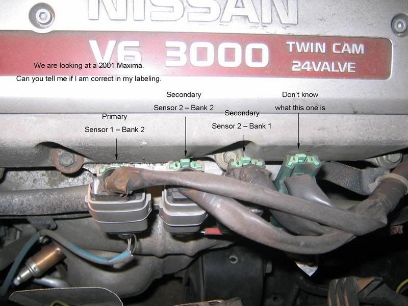

Let me know if you have more questions...
Looks like the picture from Pugman is correct, based on the position of the O2 sensors, but double check the colors based on the second diagram, which is from the TSB. Reason being I've seen O2 sensors have their positions switched around for whatever reason, either by the owner or dealer, and so the "middle two" aren't always the secondaries.
The colors indicated in the TSB diagram refer to the color of the wire shroud under the heat wrap. You can sort of see the red of Bank 2 Sensor 2 in the photo. The other one should be white.
Hope this helps.
Let me know if you have more questions...

Newbie - Just Registered
Joined: Apr 2009
Posts: 5

heater circuit
great write up did mine not too long ago and now also getting codes p0135,p0141,p0325 most seem as a heater circuit problem... thought sim would clear all that up ?it's 99 max i got would anyone know if more things are needed to clear this up? like some heater resistor i heard about ?

Junior Member
Joined: Mar 2009
Posts: 23
From: San Antonio, Texas
Really Long story but I want intell anyway!
At this point my brain and eyes both hurt from hours on the .ORG and I cant think right anymore. I had the catalyst inefficiency bank 2 code along several other codes when I first got my Max.
Story goes like this, I cleaned the MAF once to got the car running better but 50 miles down the road, crapy running... again. Once I got home, I got on what else but the .ORG, and everything I've checked so far pointed to the MAF. I took it to a mechanic and he pulled the codes, I had three. A knock sensor malfunction, the cat inefficiency and IACV. The IACV turned our to be a vacumn leak and the knock was just a fluke. He fixed the leak, cleared the codes and took it around the block, no codes.
He told me that if the SEL came back on that the Cat. may have a problem and have me a number to a guy who can look at it. Well, not but 20 miles down the road and half way home, I get the dreaded light and crappy running. I let it sit for about a week but I got to thinking about the MAF so, I cleaned it again and took off the battery for about an hour. No light, ran great! Took it up the block several times and even restarted it to see if the computer would pull the code. Nothing happened, though I have a feeling it will.
My questions are:
1). Can a MAF cause a BANK 2 Inefficiency? and which bank is bank two, front or back?
2). Which bank is necessary for fuel mixture control?
3). Which Sensor (color coding is okay, I'll have a working brain tomorrow) is for the cats and which ones do I need to replace with the simulator for this code if it rears its head after I put in a new MAF?
4). What's the difference between Primary and Secondary in a bank.
5). what about a resistor to fool the ecu's need for heat on the sensors so I could get rid of the sensor completely?
My car apparently is Cali spec... great stuff California! (not really )
)
"Help me please Maxima.org, you're my only hope" (turns to droid to turn it off) .
.
BTW. My Dad wants to know about simulators too b/c he has O2 codes on his F150, 170k+ does that ya know!
I had the catalyst inefficiency bank 2 code along several other codes when I first got my Max.Story goes like this, I cleaned the MAF once to got the car running better but 50 miles down the road, crapy running... again. Once I got home, I got on what else but the .ORG, and everything I've checked so far pointed to the MAF. I took it to a mechanic and he pulled the codes, I had three. A knock sensor malfunction, the cat inefficiency and IACV. The IACV turned our to be a vacumn leak and the knock was just a fluke. He fixed the leak, cleared the codes and took it around the block, no codes.
He told me that if the SEL came back on that the Cat. may have a problem and have me a number to a guy who can look at it. Well, not but 20 miles down the road and half way home, I get the dreaded light and crappy running. I let it sit for about a week but I got to thinking about the MAF so, I cleaned it again and took off the battery for about an hour. No light, ran great! Took it up the block several times and even restarted it to see if the computer would pull the code. Nothing happened, though I have a feeling it will.
My questions are:
1). Can a MAF cause a BANK 2 Inefficiency? and which bank is bank two, front or back?
2). Which bank is necessary for fuel mixture control?
3). Which Sensor (color coding is okay, I'll have a working brain tomorrow) is for the cats and which ones do I need to replace with the simulator for this code if it rears its head after I put in a new MAF?
4). What's the difference between Primary and Secondary in a bank.
5). what about a resistor to fool the ecu's need for heat on the sensors so I could get rid of the sensor completely?
My car apparently is Cali spec... great stuff California! (not really
)"Help me please Maxima.org, you're my only hope" (turns to droid to turn it off)
. BTW. My Dad wants to know about simulators too b/c he has O2 codes on his F150, 170k+ does that ya know!


OKay, i just installed my dual output o2sim that i recieved today from o2simulator.com
after the installation,(with the help of puppetmaster's write up) i turned on my car and the green LED was blinking slowly so i figured it was working. i let car run for a bit and the green LED stopped blinking. Is this suppose to happen? I turned off my car for a bit and turned it back on and its no longer blinking. I checked for my connections and its exactly done the way puppetmaster has it in his write up.
any advice as to why the light is no longer on?

thats weird because mine is no longer blinking. I did the wiring again to see if made a mistake and it still wont turn on. I reseted my ecu to see if my ses light stayed off and it went right back on. I think i have a bad sim.
How soon did it come back on? SES should not come back on. Mine is on because of resistor issues. It takes 30 - 50 miles once reset for it to come back on as catalyst completes and this is if you cut your O2 sensors out. If you keep the O2's and just replace outputs, SES should not come on. The OHMs for my resistor is off. My code is only for heater and not O2's or catalyst. Been meaning to fix it, but I already passed my emissions... Hope you did not fry your O2 sim.
How soon did it come back on? SES should not come back on. Mine is on because of resistor issues. It takes 30 - 50 miles once reset for it to come back on as catalyst completes and this is if you cut your O2 sensors out. If you keep the O2's and just replace outputs, SES should not come on. The OHMs for my resistor is off. My code is only for heater and not O2's or catalyst. Been meaning to fix it, but I already passed my emissions... Hope you did not fry your O2 sim.
I tried another write up shown on this site, http://www.turbomopar.com/neon/o2sim/index.html, but my sim never turned on again and i reseted my ecu prior to doing this. once i installed it like this, my ses light came back on again. i guess i got a bad sim.

any help. What about the heater wires? Does the sim do anything to prevent a heater code?

Sims do nothing for the heater. Heater is a separate wire out of the 4 wires. One wire is power, one wire output (where o2 sim should be plugged in), one wire to heat the sensor (heater) and ground. Heater resist current to ECM so you will need a resistor or keep your O2 plugged in. If you got SES in 10 miles, something went wrong.
Sims do nothing for the heater. Heater is a separate wire out of the 4 wires. One wire is power, one wire output (where o2 sim should be plugged in), one wire to heat the sensor (heater) and ground. Heater resist current to ECM so you will need a resistor or keep your O2 plugged in. If you got SES in 10 miles, something went wrong.
so once i have it installed, will it still throw a code for heater? im still a bit confused lol.
Thanks man i apreciate your help. Now i just gotta wait for my new sim.
ill keep u posted once i get it installed to see if it works fine.

So this set up did not work for me. The reason I cut off the sensors off I because I broke them Both when I was installing the headers and hat is why I went with this set up.
Now I was reading that u can weld the sensors after ur cat but that's a problem for me because I'm running straight pipes all da way.
Ink if the wiring is he same as the 5.5


Okay, i have a question. Since im runing Headers, with a test pipe, with a aftermarket resinator, and a magnaflow muffler, U think if i put back the Catalyctic converter, and weld the o2sensors behind the Catalyctic converter, would fix the SES light? Also, will the sound be affected by putting back the Catalyctic converter?
