O2 Simulator Installation
 07-31-2009, 05:28 AM
#81

alright...so right now...i have a stock exhaust and all i want right now is for my SES light to go off. is it ok for me to leave teh o2 sensor in?
and when i FINALLY get my headers adn get them installed (including my cat back exhaust) is there a bung hole for teh o2 sensor? (i plan on doing the OBX headers) if there is would teh stock o2 sensor be fine or would i need to do teh AEM wideband o2 sensor for it to work correctly? i have more questions regarding teh that o2 sensor but let me get the basics first
and when i FINALLY get my headers adn get them installed (including my cat back exhaust) is there a bung hole for teh o2 sensor? (i plan on doing the OBX headers) if there is would teh stock o2 sensor be fine or would i need to do teh AEM wideband o2 sensor for it to work correctly? i have more questions regarding teh that o2 sensor but let me get the basics first

 01-15-2010, 06:57 PM
#83

Wanted to bump this for the great write up and to see what I can do about my problem with the o2s on my 02.
I have codes p0031 (Oxygen (A/F) Sensor Heater Control Circuit Low (Bank 1 Sensor 1 - this is a primary right?), p0132 (O2 Oxygen Sensor Circuit High Voltage (Bank1, Sensor1)), and p0138 (O2 Oxygen Sensor Circuit High Voltage (Bank1, Sensor2)).
I got one of these codes after I did a test pipe (which is weird, because since it's an 02, it has no o2s after the cat - figured it was a fluke) and I got the rest of these after I took the car to have the headers installed, which probably means that they could have dropped them as the o2s are very sensitive.
Would I need to get new o2s to solve the problem? Would the problem even go away with OBX headers or should I use a non-fouler? I need to know soon because my inspection is way out and I need to get it done. Thanks!
01-15-2010, 11:41 PM
#84

Wanted to bump this for the great write up and to see what I can do about my problem with the o2s on my 02.
I have codes p0031 (Oxygen (A/F) Sensor Heater Control Circuit Low (Bank 1 Sensor 1 - this is a primary right?), p0132 (O2 Oxygen Sensor Circuit High Voltage (Bank1, Sensor1)), and p0138 (O2 Oxygen Sensor Circuit High Voltage (Bank1, Sensor2)).
I got one of these codes after I did a test pipe (which is weird, because since it's an 02, it has no o2s after the cat - figured it was a fluke) and I got the rest of these after I took the car to have the headers installed, which probably means that they could have dropped them as the o2s are very sensitive.
Would I need to get new o2s to solve the problem? Would the problem even go away with OBX headers or should I use a non-fouler? I need to know soon because my inspection is way out and I need to get it done. Thanks!
I have codes p0031 (Oxygen (A/F) Sensor Heater Control Circuit Low (Bank 1 Sensor 1 - this is a primary right?), p0132 (O2 Oxygen Sensor Circuit High Voltage (Bank1, Sensor1)), and p0138 (O2 Oxygen Sensor Circuit High Voltage (Bank1, Sensor2)).
I got one of these codes after I did a test pipe (which is weird, because since it's an 02, it has no o2s after the cat - figured it was a fluke) and I got the rest of these after I took the car to have the headers installed, which probably means that they could have dropped them as the o2s are very sensitive.
Would I need to get new o2s to solve the problem? Would the problem even go away with OBX headers or should I use a non-fouler? I need to know soon because my inspection is way out and I need to get it done. Thanks!
Do both when installing your OBX headers.
As for the secondaries (Sensor2), get a simulator and heater resistors and eliminate those completely.
01-16-2010, 07:59 AM
#85
You should replace your primary o2's, as it seems that the bank 1 primary is already bad, so the bank 2 will probably follow shortly.
Do both when installing your OBX headers.
As for the secondaries (Sensor2), get a simulator and heater resistors and eliminate those completely.
Do both when installing your OBX headers.
As for the secondaries (Sensor2), get a simulator and heater resistors and eliminate those completely.
Where are the location of these o2s? Hoping someone has pictures
 01-16-2010, 02:54 PM
#87
OBX headers are already on the car. I'm just trying to get rid of the SES at this point. So I should replace both of the o2s or just the bank 1 sensor 1? I am wonder if the bank 1 sensor 2 is reading high because the primary if messed up.
Where are the location of these o2s? Hoping someone has pictures
Where are the location of these o2s? Hoping someone has pictures
Sensor 1 means primary (before cat) and Sensor 2 means secondary (after cat)
Bank 1 and bank 2 sensor 2 will show an error because you deleted your precats with the headers. You'll need a simulator and heater resistors to fully get rid of your secondaries without any codes.
01-23-2010, 10:49 PM
#88
:)

Join Date: Nov 2007
Posts: 5
Ok, so I got the P0420/P0430 blues like the rest of you guys in my 2000 cali max. I just installed the o2 sim from o2simulator.com and also installed resistors totally bypassing the original rear 02s. Don't get the resistors from the o2 sim site as they are the wrong resistance. The FSM says the heaters for the Rear o2's should be 2.3-4.3ohms resistance. I picked up a pair of 25W 3.3ohm resistors from Frys and they get very very hot, keep anything not metal away from them, mount them with some kind of metal bracket to something metal. I will report back after this thing passes it's system readiness test to let you guys know how well it works. I hope it works ok as I have to get my emissions done by the end of the month.
02-10-2010, 09:21 AM
#90

you need to get 2 4 ohm 25watt(at least) resistors to successfully get rid of a SES for heater codes(for cars with no secondaries). one for each bank, power going to one side of the resistor and the heater output signal wire on the other side...and make sure they are not wrapped up with the wiring,they get very hot and will melt wires fast(ask me how i know) lol
02-10-2010, 09:41 AM
#91
you need to get 2 4 ohm 25watt(at least) resistors to successfully get rid of a SES for heater codes(for cars with no secondaries). one for each bank, power going to one side of the resistor and the heater output signal wire on the other side...and make sure they are not wrapped up with the wiring,they get very hot and will melt wires fast(ask me how i know) lol
These can be found at Radioshack.

 02-11-2010, 07:58 AM
#94
02-11-2010, 08:34 AM
#95
06-03-2010, 02:39 PM
#97

I ended up using the o2 sim anyway. I just installed if off of my ecu. I didn't feel like putting the chip in the hot engine bay. The o2 sensors still remain connected for the heater code though.


 01-02-2011, 09:29 AM
#101
Newbie - Just Registered

Join Date: Nov 2004
Posts: 6
02sims still being sold
Yes, they are still selling the o2 sims. I tried getting them from o2sim.com but it was real shady. There was a third party who handled the payment. The website does not have adequate support or reply anymore. No one has responded to any of my inquiries there, or anyone else on their forum, for that matter. I had the third party eventually cancel out my transaction and refund my money.
Fortunately, I found a guy on Amazon.com who sells some o2 sims. Unfortunately, he only has single outputs. I bought the ones with a heater circuit in them. They were not as cheap, actually double the cost. They came promptly within 4 days (that was christmas weekend too!), via USPS. Amazon said they would come by Jan19th!
I would recommend NOT getting the ones with heater circuit. Placement MUST be up against something metallic to dissipate the heat. But I suspect that it will greatly reduce the life of the sim. The resistance on the circuit was at 50ohms. I got codes thrown at me (p0057 and p0037) even after I hooked up the heater circuit.
I eventually plugged in the old o2 sensors and used the heaters on that. I suspect the computer actually looks at how long it has the heater on and if it is on too long, then it will throw a code. Either that or the heater circuit is not adequate for our 5th gens.
I did an engine and tranny swap on my 03 5.5gen. So, also had cattman headers put in (along with New Tokico Illuminas, H&R springs, and Jim Wolf Pop Charger ). I tried to hook the sims and heater into some extra O2 sensor wires that came with the new(er) engine, they just simply cut off the o2 sensor. But as talked about previously, the wires are probably too sensitive to do any splicing. I tried using the 3M Butt-end splicers which also have silicone in them to insulate.
Despite using the O2 sensor wires, I got codes as above mentioned. I finally bit the bullet and spliced the heater circuit into the wiring harness. Still got the codes. So, finally spliced all the o2 sim into the car's wiring harness as Puppetmaster wrote up. Holding my breath I connected the original o2 sensors and cleared the codes.....Thankfully, no code so far.
For Puppetmaster: Should I have hooked the O2 sims up into wiring harness AND also hooked in the heater circuit as well? Interestingly, I have found that the heater circuit needs power from the Red/yellow wire and hook the other end up to the return of the heater circuit back to ECM (whatever color wires they were). Otherwise, if I wired it: ECM heater wire -> Resister/Heater Circuit from o2sim -> Ground (black wire on harness not direct car ground), neither the resistors I used (from Radioshack) or heater circuit on the o2 sim would heat up. This I take meant a non functioning circuit, as I still got codes. Since my currect set up is working, I don't wanna fiddle with the 02sim heater circuit or resistors any more, it's taken 3 days out of me to diagnose.
Also, while the SES light did not come one, with OBDwiz, there was a p0057 code pending that was seen...maybe because it was the first crank after this hook up. I was tempted to clear that out as well, but chose to leave it. That was like 3 days ago.
I am waiting to get cattman catback and Brian has agreed to have them weld on some O2 sensor bungs. I think I was the last order he needed to get this batch rolling. Maybe I'll put the sensors back on there, rather than leaving them ziptied in my engine bay.
Fortunately, I found a guy on Amazon.com who sells some o2 sims. Unfortunately, he only has single outputs. I bought the ones with a heater circuit in them. They were not as cheap, actually double the cost. They came promptly within 4 days (that was christmas weekend too!), via USPS. Amazon said they would come by Jan19th!
I would recommend NOT getting the ones with heater circuit. Placement MUST be up against something metallic to dissipate the heat. But I suspect that it will greatly reduce the life of the sim. The resistance on the circuit was at 50ohms. I got codes thrown at me (p0057 and p0037) even after I hooked up the heater circuit.
I eventually plugged in the old o2 sensors and used the heaters on that. I suspect the computer actually looks at how long it has the heater on and if it is on too long, then it will throw a code. Either that or the heater circuit is not adequate for our 5th gens.
I did an engine and tranny swap on my 03 5.5gen. So, also had cattman headers put in (along with New Tokico Illuminas, H&R springs, and Jim Wolf Pop Charger
). I tried to hook the sims and heater into some extra O2 sensor wires that came with the new(er) engine, they just simply cut off the o2 sensor. But as talked about previously, the wires are probably too sensitive to do any splicing. I tried using the 3M Butt-end splicers which also have silicone in them to insulate.Despite using the O2 sensor wires, I got codes as above mentioned. I finally bit the bullet and spliced the heater circuit into the wiring harness. Still got the codes. So, finally spliced all the o2 sim into the car's wiring harness as Puppetmaster wrote up. Holding my breath I connected the original o2 sensors and cleared the codes.....Thankfully, no code so far.
For Puppetmaster: Should I have hooked the O2 sims up into wiring harness AND also hooked in the heater circuit as well? Interestingly, I have found that the heater circuit needs power from the Red/yellow wire and hook the other end up to the return of the heater circuit back to ECM (whatever color wires they were). Otherwise, if I wired it: ECM heater wire -> Resister/Heater Circuit from o2sim -> Ground (black wire on harness not direct car ground), neither the resistors I used (from Radioshack) or heater circuit on the o2 sim would heat up. This I take meant a non functioning circuit, as I still got codes. Since my currect set up is working, I don't wanna fiddle with the 02sim heater circuit or resistors any more, it's taken 3 days out of me to diagnose.
Also, while the SES light did not come one, with OBDwiz, there was a p0057 code pending that was seen...maybe because it was the first crank after this hook up. I was tempted to clear that out as well, but chose to leave it. That was like 3 days ago.
I am waiting to get cattman catback and Brian has agreed to have them weld on some O2 sensor bungs. I think I was the last order he needed to get this batch rolling. Maybe I'll put the sensors back on there, rather than leaving them ziptied in my engine bay.
Last edited by spidey_mon; 01-03-2011 at 10:03 AM.
 10-01-2011, 03:59 PM
#104
Newbie - Just Registered

Join Date: Sep 2011
Location: killingly
Posts: 2
What code is po217, po160,po140, i know what they say they are from the scan tool, but im looking for what exactly what i have to replace? po217 says engine coolant over temp, but the car has new thermostat, radiator also.
12-04-2011, 04:04 PM
#105
Supporting Maxima.org Member


Join Date: Dec 2004
Location: Atlanta, GA
Posts: 1,183
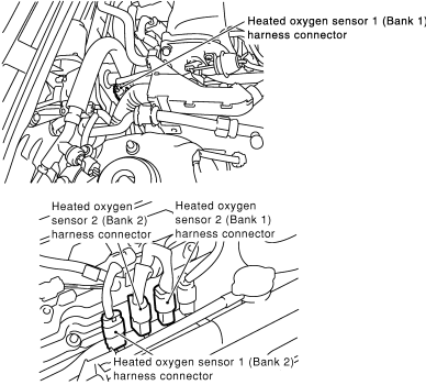
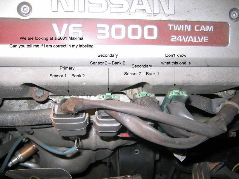
Extra bump. I just checked FSM for 2002-2003 and the sensor locations are the same. See image below for verification that locations did not change from 2000-2001 for downstreams.
Sent you a PM but I'll also post it here for others' benefit...
Looks like the picture from Pugman is correct, based on the position of the O2 sensors, but double check the colors based on the second diagram, which is from the TSB. Reason being I've seen O2 sensors have their positions switched around for whatever reason, either by the owner or dealer, and so the "middle two" aren't always the secondaries.
The colors indicated in the TSB diagram refer to the color of the wire shroud under the heat wrap. You can sort of see the red of Bank 2 Sensor 2 in the photo. The other one should be white.
Hope this helps.

Let me know if you have more questions...
Looks like the picture from Pugman is correct, based on the position of the O2 sensors, but double check the colors based on the second diagram, which is from the TSB. Reason being I've seen O2 sensors have their positions switched around for whatever reason, either by the owner or dealer, and so the "middle two" aren't always the secondaries.
The colors indicated in the TSB diagram refer to the color of the wire shroud under the heat wrap. You can sort of see the red of Bank 2 Sensor 2 in the photo. The other one should be white.
Hope this helps.
Let me know if you have more questions...
12-14-2011, 02:19 PM
#106
What happens if you hook up 2 signal wires from 2 separate o2 sensors to a single-output o2 sim?

Well just for input...the seller told me the single output o2 sim will work fine on 2 o2 sensors. I'm going to try it out today. Of course, the heaters from both o2s wouldn't be a good idea so I'll leave the o2 sensors hooked up.
Well just for input...the seller told me the single output o2 sim will work fine on 2 o2 sensors. I'm going to try it out today. Of course, the heaters from both o2s wouldn't be a good idea so I'll leave the o2 sensors hooked up.
Last edited by NmexMAX; 12-20-2011 at 08:59 AM.
 12-29-2011, 10:10 AM
#108
epic bump.
Do you need a heater resistor to install the O2 sim or can I just splice it right into the O2 sensors and hide them under the cover. I am very newb to this.
My car is almost 2 months on expired plates and I need to get it to pass inspection STAT. If anyone is near the St Louis area- I will even pay for help/install.
12-29-2011, 11:09 AM
#109

epic bump.
Do you need a heater resistor to install the O2 sim or can I just splice it right into the O2 sensors and hide them under the cover. I am very newb to this.
My car is almost 2 months on expired plates and I need to get it to pass inspection STAT. If anyone is near the St Louis area- I will even pay for help/install.
Do you need a heater resistor to install the O2 sim or can I just splice it right into the O2 sensors and hide them under the cover. I am very newb to this.
My car is almost 2 months on expired plates and I need to get it to pass inspection STAT. If anyone is near the St Louis area- I will even pay for help/install.
http://www.3sx.com/store/comersus_vi...?idProduct=769
Follow instructions and enjoy SES free life!!

 01-06-2012, 07:53 PM
#116
Opening this back up because I am so stressed and having a hell of a time with this.
I installed the o2 sim as instructed in Puppermaster's write up step for step (I know that is correct)and I am getting the blinking green light.
Not sure if this matters...
I do have the 2nd Harness(the green one) resting on top of the engine(like in the write up) while the 3rd harness(the dark blue) is plugged in the exhaust.
I am still showing a p0051 after resetting the ECU a few times.
Can anyone please help as I want to get this alleviated and I am almost to the point of removing the headers or going bat s1t crazy.
I am very new to doing this- as I have never dealt with the issues of headers before so be gentle if this is an easy fix or if I am overlooking anything.
here are images of what I have(sorry it was dark and I just have the phone flash)


thank you in advance
I installed the o2 sim as instructed in Puppermaster's write up step for step (I know that is correct)and I am getting the blinking green light.
Not sure if this matters...
I do have the 2nd Harness(the green one) resting on top of the engine(like in the write up) while the 3rd harness(the dark blue) is plugged in the exhaust.
I am still showing a p0051 after resetting the ECU a few times.
Can anyone please help as I want to get this alleviated and I am almost to the point of removing the headers or going bat s1t crazy.
I am very new to doing this- as I have never dealt with the issues of headers before so be gentle if this is an easy fix or if I am overlooking anything.
here are images of what I have(sorry it was dark and I just have the phone flash)
thank you in advance
01-06-2012, 08:04 PM
#117

ok so we know you having a heater circuit issue bank 2 sensor 1 correct? if so do you still have the o2 plugged in?im thinking your sim does not work for the heater circuit or you may need to search for the way to bypass the heater circuit.or swap a different 02 in its place to see if the one in question was damaged when it was removed from the manifold
01-06-2012, 08:11 PM
#118
O2 sensor simulator
OBD-II cars (1996 - present) have the two O2 sensors to measure the amount of oxygen in the exhaust gas. First sensor is measuring it right after gases escape engine and this data is used to adjust fuel trim of the engine, as well as catch some faulty conditions. The second sensor is located after the catalic converter, and is used to detect the health of catalic converter, it does not influence the car's performance in any way. The ECU expects the signal from the sensor to be oscillating from below 0.4v to above 0.6v, but not above 1.2v, every few seconds when cruising.
If the exhaust system is modified to eliminate the catalytic converter the ECU will detect this and throw a code, turning on the check engine light on the instrument cluster. The ECU usually takes a while to detect and report this condition. The ECU can be reset and the error code can be cleared but it's not convenient and hinders one's ability to know if there are any other error codes due to a constantly illuminated check engine light.
It is possible to simulate the O2 sensor to eliminate the check engine light. There are two methods to doing this, one is a simpler circuit that creates a load and uses a capacitor to simulate the o2 sensor, while much easier to construct, results may vary. The second more complex circuit is claser to the signal of an o2 sensor and should be used if one has the resources to build it.
O2 sensor simulator circuit #1
The following circuit is very easy to construct. The capacitor and the 1Mohm resistor should be soldered together in parallel. Then the old o2 sensor should be cut off, leaving the plug and wires in tact. After stripping the wires, the capacitor and resistor should be soldered between the blue and white wires, or whichever wires are responsible for the sensor itself. After that the whole thing should be taped or have heatshrink tubing placed on it to avoid any shorts. The other pair, which is for the heater element should be soldered to a resistor of ~ 12 Ohms to create a load, if there is no load on the heater element wires and they are left alone, the ECU will create an error code.

IMPORTANT: Use resistors that are rated for 12 watts of current or use many in parallel. The resistors will get extremely hot and if not rated for the current could start a car fire. Heatsinks can also be used to help.
O2 sensor simulator circuit #2
Building the following circuit will provide an oscillating signal generator with just the right frequency and voltage to fool the ECU. It is based on classical stable operating mode of 555 timer. The parts usually cost about $ 15 - $ 20 at RadioShack, however going to a local mom and pop electronics shop will make the project far cheaper. Some RadioShack stores are discontinuing carrying any electronic components.
Components:
R1 100 K Ohm
R2 1 M Ohm
R3 100 K Ohm
R4 10 K Ohm
C1 4.7 uF
C2 22 uF
D1 1.7v@20mA LED
D2 1.7v@20mA LED

Hookup:
Power source - Ignition, or to the ECU PIN #1
Ground - One of the ground points or ECU PIN #80
OUT - ECU PIN #47 (disconnect the O2 sensor wire)
RadioShack part numbers:
276-309 - 5mm wide angle red led 1.7v, 20mA
276-1723 - The 555 programmable timer
276-1995A - The 8 pin socket for timer chip. It makes soldering safer and replacement easier
276-150A - Generic PC board
64-3052A - Pack of blue tap-in connectors
278-1225 - Stranded wires (black, red and green)
270-1801 - Small black plastic project box 3 x 2 x 1
272-1024 - Capacitor, 4.7uF
272-1026 - Capacitor, 22uF
Additional notes
If you use different flavors of 555 timer chip or LEDs with different parameters you will need to readjust the values of R4 and R2 to get the interval and output voltage right.
Don't attach it directly to the ECU right after assembly. Instead attach it to the battery and check the output. You should get approximately 0v/0.7v flipping about every 3.3 seconds when the car is not running, and 0v/0.9v when the car is running. The current should stay below 10mA.
One LED should be always on whenever the power is supplied. Another LED indicates when the output signal is high, so it should go on and off with the signal.
When tapping the ECU wires, triple check everything before hooking up the oscillator. The power source should read 0v when the key is removed, about 12.6v when they key is at ACC and about 14.3 when the alternator is running. The resistance between ground wire and the body shield of the ECU should be 0 ohms. And it would be best if you run the car and monitor the voltage of the original oxygen sensor wire before cutting it to make sure you have indeed got the right one. The resistance between ECU PIN #47 and ground is about 1.3 to 1.6 M Ohm.
The original sensor should still be dangling around, or plugged into the downpipe. The reason is that ECU also monitors the resistance of heater circuit inside the sensor. If you want to COMPELTELY disconnect it, you will need to measure the resistance of the heater circuit and install the right resistor between ECU PIN #72 and ECU PIN #31 Anyway, there is no need to do it if you just leave O2 sensor alone and only intercept the oxygen signal wire.
Above testing and precautions will prevent the ECU from getting fried.
OBD-II cars (1996 - present) have the two O2 sensors to measure the amount of oxygen in the exhaust gas. First sensor is measuring it right after gases escape engine and this data is used to adjust fuel trim of the engine, as well as catch some faulty conditions. The second sensor is located after the catalic converter, and is used to detect the health of catalic converter, it does not influence the car's performance in any way. The ECU expects the signal from the sensor to be oscillating from below 0.4v to above 0.6v, but not above 1.2v, every few seconds when cruising.
If the exhaust system is modified to eliminate the catalytic converter the ECU will detect this and throw a code, turning on the check engine light on the instrument cluster. The ECU usually takes a while to detect and report this condition. The ECU can be reset and the error code can be cleared but it's not convenient and hinders one's ability to know if there are any other error codes due to a constantly illuminated check engine light.
It is possible to simulate the O2 sensor to eliminate the check engine light. There are two methods to doing this, one is a simpler circuit that creates a load and uses a capacitor to simulate the o2 sensor, while much easier to construct, results may vary. The second more complex circuit is claser to the signal of an o2 sensor and should be used if one has the resources to build it.
O2 sensor simulator circuit #1
The following circuit is very easy to construct. The capacitor and the 1Mohm resistor should be soldered together in parallel. Then the old o2 sensor should be cut off, leaving the plug and wires in tact. After stripping the wires, the capacitor and resistor should be soldered between the blue and white wires, or whichever wires are responsible for the sensor itself. After that the whole thing should be taped or have heatshrink tubing placed on it to avoid any shorts. The other pair, which is for the heater element should be soldered to a resistor of ~ 12 Ohms to create a load, if there is no load on the heater element wires and they are left alone, the ECU will create an error code.
IMPORTANT: Use resistors that are rated for 12 watts of current or use many in parallel. The resistors will get extremely hot and if not rated for the current could start a car fire. Heatsinks can also be used to help.
O2 sensor simulator circuit #2
Building the following circuit will provide an oscillating signal generator with just the right frequency and voltage to fool the ECU. It is based on classical stable operating mode of 555 timer. The parts usually cost about $ 15 - $ 20 at RadioShack, however going to a local mom and pop electronics shop will make the project far cheaper. Some RadioShack stores are discontinuing carrying any electronic components.
Components:
R1 100 K Ohm
R2 1 M Ohm
R3 100 K Ohm
R4 10 K Ohm
C1 4.7 uF
C2 22 uF
D1 1.7v@20mA LED
D2 1.7v@20mA LED
Hookup:
Power source - Ignition, or to the ECU PIN #1
Ground - One of the ground points or ECU PIN #80
OUT - ECU PIN #47 (disconnect the O2 sensor wire)
RadioShack part numbers:
276-309 - 5mm wide angle red led 1.7v, 20mA
276-1723 - The 555 programmable timer
276-1995A - The 8 pin socket for timer chip. It makes soldering safer and replacement easier
276-150A - Generic PC board
64-3052A - Pack of blue tap-in connectors
278-1225 - Stranded wires (black, red and green)
270-1801 - Small black plastic project box 3 x 2 x 1
272-1024 - Capacitor, 4.7uF
272-1026 - Capacitor, 22uF
Additional notes
If you use different flavors of 555 timer chip or LEDs with different parameters you will need to readjust the values of R4 and R2 to get the interval and output voltage right.
Don't attach it directly to the ECU right after assembly. Instead attach it to the battery and check the output. You should get approximately 0v/0.7v flipping about every 3.3 seconds when the car is not running, and 0v/0.9v when the car is running. The current should stay below 10mA.
One LED should be always on whenever the power is supplied. Another LED indicates when the output signal is high, so it should go on and off with the signal.
When tapping the ECU wires, triple check everything before hooking up the oscillator. The power source should read 0v when the key is removed, about 12.6v when they key is at ACC and about 14.3 when the alternator is running. The resistance between ground wire and the body shield of the ECU should be 0 ohms. And it would be best if you run the car and monitor the voltage of the original oxygen sensor wire before cutting it to make sure you have indeed got the right one. The resistance between ECU PIN #47 and ground is about 1.3 to 1.6 M Ohm.
The original sensor should still be dangling around, or plugged into the downpipe. The reason is that ECU also monitors the resistance of heater circuit inside the sensor. If you want to COMPELTELY disconnect it, you will need to measure the resistance of the heater circuit and install the right resistor between ECU PIN #72 and ECU PIN #31 Anyway, there is no need to do it if you just leave O2 sensor alone and only intercept the oxygen signal wire.
Above testing and precautions will prevent the ECU from getting fried.
01-06-2012, 08:25 PM
#119
the 3rd harness from the left(dark blue harness/white o2 wire) is plugged into the exhaust.
So it could just be that o2 sensor is bad or damaged o2 sensor(possibly the result of a careless install)?
The post above is way beyond my knowledge and skill set.
So it could just be that o2 sensor is bad or damaged o2 sensor(possibly the result of a careless install)?
The post above is way beyond my knowledge and skill set.
01-06-2012, 08:29 PM
#120
i know they are sensitive i changed the exhaust on the 97 a few months ago and dropped the one at the rear cat about 8 inches to the ground when screwing it back in and now it gets a code every few days for it all i have to do is tap on it with a screw driver and the code goes away.so yes it could of been damaged they are a pain to get out if there oe.