HOW-TO WORKLOG: LED Loaded Instrument Cluster (+60 LEDs!) BRIGHTEST ORG CLUSTER YET
 06-23-2006, 03:35 AM
#1
HOW-TO WORKLOG: LED Loaded Instrument Cluster (+60 LEDs!) BRIGHTEST ORG CLUSTER YET
Welcome, ladies & gents! This thread will be detailing how to create what I promise to be the BRIGHTEST instrument cluster yet seen on the .org. We will be utilizing SMT LEDs mounted on a PCB that will be retrofitted into the stock instrument cluster housing. This is essentially considered a ‘worklog’ as I will be updating the thread as progress is made. Also, for those wondering about the interior overhaul – this is the final project, so I will be updating that thread with this AND all of the other works that have been done since its last update. As with any HOW-TO, you mess it up, that’s on you. Let’s start with a list of supplies…
TOOLS
- Wire Stripper
- Wire Cutters
- Soldering Iron, 25W minimum
- Dremel w/ cutting wheel & sanding drum accessories
SUPPLIES
I purchased the majority of these items from mouser.com. All of these items can be found there A LOT cheaper than what you’d find at Radio Shack. I will update the list with part numbers later on, as to make it easier to find them on the site.
- Solder
- Heatsink Paste
- 20 or 22 Gauge Wire
- 120Ω Resistors x 100
- Aluminum Heatsink x 4
- TO-220 Voltage Regulator x 4
- PCB/Prototyping Board w/ Copper Holes
- SMT LEDs (you choose the color, get ‘em on eBay) x 100
- #4-40 �” Bolts (You can get these from Josh’s sponsor, aka Home Depot)
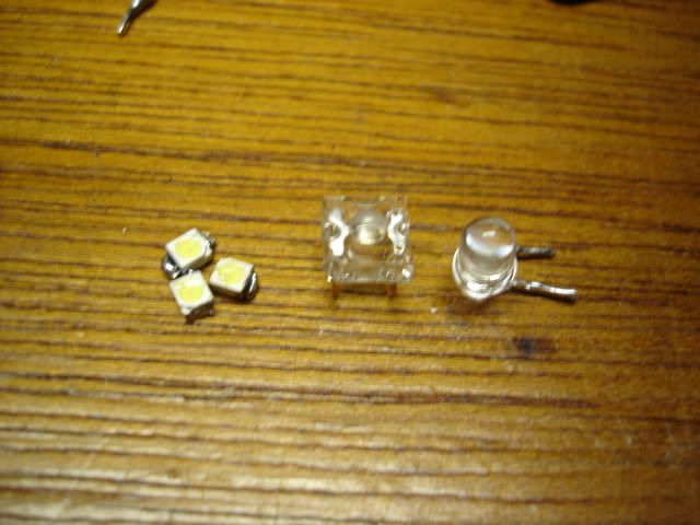
LED COMPARISON
A lot of people have been asking about this one. In this picture you will see a comparison of three different types of LEDs. The first ones are the SMT LEDs, you can see how tiny they are. The middle one is a superflux LED, and the one on the right is a 5mm LEDs. You can see that we are using some tiny LEDs here!
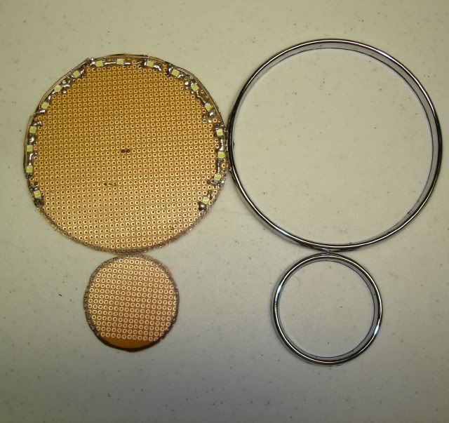
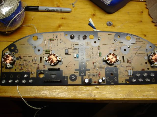
STEP I – BOARD CUTTING
The first step will involve cutting the PCB as to accommodate our LEDs. You will need 4 disks total. Two will be 2” in diameter for the fuel and temperature gauges; two will be 4” for the tachometer and the speedometer. Measure them however you wish. I personally chose to use my chrome gauge rings as the template.
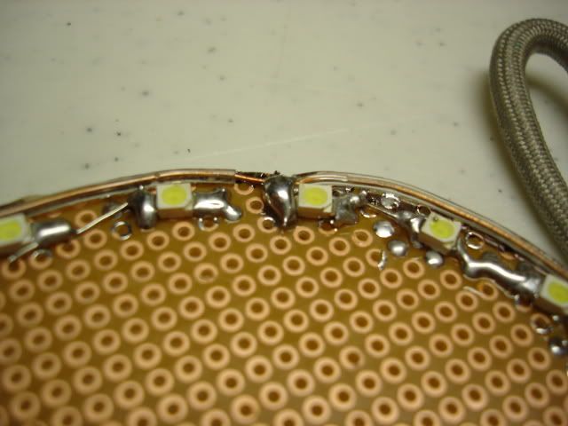
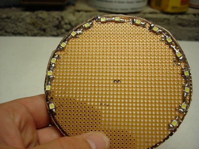
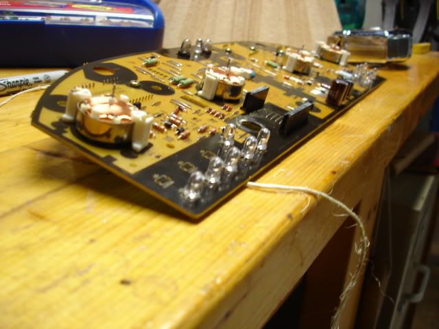
STEP II – LED SOLDERING
You will notice there are copper leads on either end of the LEDs. You will begin by putting a dab of solder on the hole where you wish to put your LED, then putting the LED into position, then soldering it on the board. Solder however many LEDs as you wish, making sure they all go (+) to (-). The LEDs will be soldered in runs of three, so slap some solder down between the first-to-second, second-to third LEDs to make each run.
STEP III – POSITIVE LEADS
In order to make the positive leg of the circuit, begin by taking a small piece of wire, strip the end, and solder it onto the positive end of the first LED of the first run. Then run this lead to the first LED of the second run. Get a new piece of wire, make another lead connecting the first LED of the second run to the first LED of the third run, so on and so on.
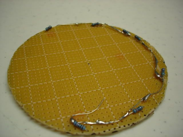
STEP IV – NEGATIVE LEADS
You will be doing the same thing you did in STEP III, only this time you will be connecting the negative leads. Thread one end of the resistor through the bottom of the disk and connect to the negative lead of the third LED of the first run. Continue this for the remaining runs, snipping off the extra length. Turn the disk over, and connect each OPEN resistor lead together.
TOOLS
- Wire Stripper
- Wire Cutters
- Soldering Iron, 25W minimum
- Dremel w/ cutting wheel & sanding drum accessories
SUPPLIES
I purchased the majority of these items from mouser.com. All of these items can be found there A LOT cheaper than what you’d find at Radio Shack. I will update the list with part numbers later on, as to make it easier to find them on the site.
- Solder
- Heatsink Paste
- 20 or 22 Gauge Wire
- 120Ω Resistors x 100
- Aluminum Heatsink x 4
- TO-220 Voltage Regulator x 4
- PCB/Prototyping Board w/ Copper Holes
- SMT LEDs (you choose the color, get ‘em on eBay) x 100
- #4-40 �” Bolts (You can get these from Josh’s sponsor, aka Home Depot)
LED COMPARISON
A lot of people have been asking about this one. In this picture you will see a comparison of three different types of LEDs. The first ones are the SMT LEDs, you can see how tiny they are. The middle one is a superflux LED, and the one on the right is a 5mm LEDs. You can see that we are using some tiny LEDs here!
STEP I – BOARD CUTTING
The first step will involve cutting the PCB as to accommodate our LEDs. You will need 4 disks total. Two will be 2” in diameter for the fuel and temperature gauges; two will be 4” for the tachometer and the speedometer. Measure them however you wish. I personally chose to use my chrome gauge rings as the template.
STEP II – LED SOLDERING
You will notice there are copper leads on either end of the LEDs. You will begin by putting a dab of solder on the hole where you wish to put your LED, then putting the LED into position, then soldering it on the board. Solder however many LEDs as you wish, making sure they all go (+) to (-). The LEDs will be soldered in runs of three, so slap some solder down between the first-to-second, second-to third LEDs to make each run.
STEP III – POSITIVE LEADS
In order to make the positive leg of the circuit, begin by taking a small piece of wire, strip the end, and solder it onto the positive end of the first LED of the first run. Then run this lead to the first LED of the second run. Get a new piece of wire, make another lead connecting the first LED of the second run to the first LED of the third run, so on and so on.
STEP IV – NEGATIVE LEADS
You will be doing the same thing you did in STEP III, only this time you will be connecting the negative leads. Thread one end of the resistor through the bottom of the disk and connect to the negative lead of the third LED of the first run. Continue this for the remaining runs, snipping off the extra length. Turn the disk over, and connect each OPEN resistor lead together.
Last edited by Metal Maxima; 09-29-2009 at 06:13 PM.
 06-23-2006, 03:36 AM
#2
STEP V - TO-220 VOLTAGE REGULATOR
Now that the outer ring of LEDs has been completed, it�s time to test everything out! Get used to this, as we will be testing this quite frequently throughout. First things first, Take a TO-220, put some thermal paste on the back, and attach an aluminum heatsink to the regulator with a #4-40 bolt. You will see three legs on the regulator. The leftmost leg facing you will be the power supply in. The middle leg goes to ground, the rightmost will supply the board. Simply make a temporary connection to the regulator.
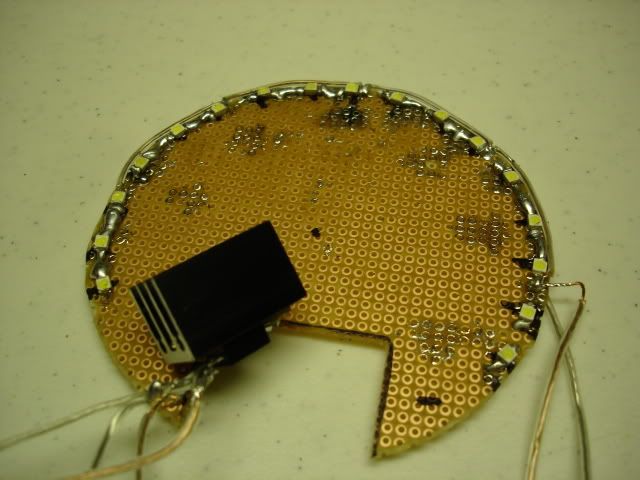
STEP VI - TESTING
Now that the outer ring of LEDs has been completed, it�s time to test everything out! Get Pretty simply here. Connect the leads of the regulator to the respective leads on the battery and test. Make sure the leads on the assembly are not touching any metal on the chassis�or anywhere for that matter!

THREE YEARS LATER...LOL
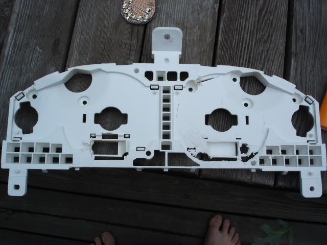
STEP VII - CLUSTER TRIM MODIFICATION
Time to make it all fit. One thing you've probably noticed is that when you install an LED is that you still have somewhat of a localized affect. That's because LED do not reach their full spread until about an inch or more from the origin of the light, ergo, we need to provide some space to make 'em shine. Hack away.[/COLOR][/B]

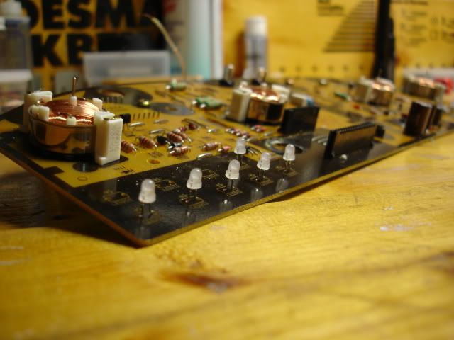
STEP VIII - OE BULB SWAP
While we're at it, might as well replace those ugly green and orange bulbs with some nice blue ones! Use some copper desolder braid to adsorb the OE solder and pop the originals out, and place the new ones in.[/COLOR][/B]
Now that the outer ring of LEDs has been completed, it�s time to test everything out! Get used to this, as we will be testing this quite frequently throughout. First things first, Take a TO-220, put some thermal paste on the back, and attach an aluminum heatsink to the regulator with a #4-40 bolt. You will see three legs on the regulator. The leftmost leg facing you will be the power supply in. The middle leg goes to ground, the rightmost will supply the board. Simply make a temporary connection to the regulator.
STEP VI - TESTING
Now that the outer ring of LEDs has been completed, it�s time to test everything out! Get Pretty simply here. Connect the leads of the regulator to the respective leads on the battery and test. Make sure the leads on the assembly are not touching any metal on the chassis�or anywhere for that matter!
THREE YEARS LATER...LOL
STEP VII - CLUSTER TRIM MODIFICATION
Time to make it all fit. One thing you've probably noticed is that when you install an LED is that you still have somewhat of a localized affect. That's because LED do not reach their full spread until about an inch or more from the origin of the light, ergo, we need to provide some space to make 'em shine. Hack away.[/COLOR][/B]
STEP VIII - OE BULB SWAP
While we're at it, might as well replace those ugly green and orange bulbs with some nice blue ones! Use some copper desolder braid to adsorb the OE solder and pop the originals out, and place the new ones in.[/COLOR][/B]
Last edited by Metal Maxima; 09-29-2009 at 06:33 PM.
06-23-2006, 03:37 AM
#3
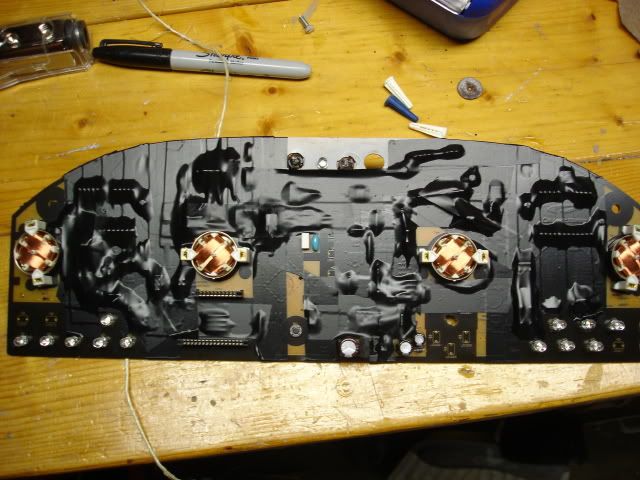
STEP IX - THE GREAT TAPE-OFF
We'll need to dress her head to toe in some electrical tape since we'll be placing the boards directly atop the OE board...so tape away...DO NOT GET LAZY ON THIS STEP, FOR FACK'S SAKE!!!
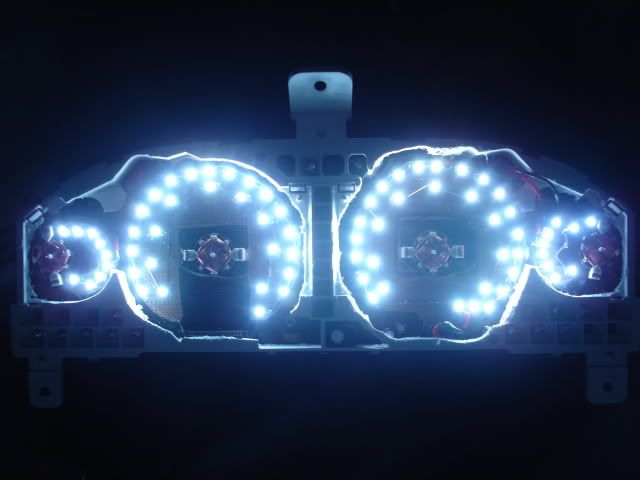
STEP X - PUTTING IT ALL TOGETHER
Place everything together...you're almost done! I used GOOP all-purpose adhesive to ensure a nice fit.

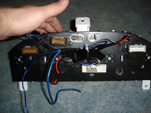
STEP XI - WIRE ROUTING
Here's where you're going to have to get creative (although I'll assume that's a given if you've gotten that far). Drill holes through the plastic and route the wiring, and tie in to the TO-220 assembly. Depending on the amperage rating for your array, you may need only one...but I did one per as I was not going to risk anything to chance.
Last edited by Metal Maxima; 09-29-2009 at 06:43 PM.
06-23-2006, 03:38 AM
#4
STEP XI - TESTING
Take your positive and negative leads to the old battery and fire away.
STEP XII - PUT YOUR GAME FACE ON!
Silver vs. Black..your call...
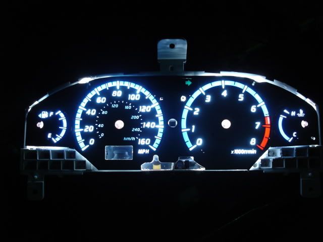
STEP XIII - CELEBRATE!
Pat yourself on the back for completing one of the most overkill LED projects you can do...and enjoy your cluster, you're going to love it!!!

Take your positive and negative leads to the old battery and fire away.
STEP XII - PUT YOUR GAME FACE ON!
Silver vs. Black..your call...
STEP XIII - CELEBRATE!
Pat yourself on the back for completing one of the most overkill LED projects you can do...and enjoy your cluster, you're going to love it!!!
Last edited by Metal Maxima; 09-29-2009 at 06:47 PM.
06-23-2006, 03:39 AM
#5
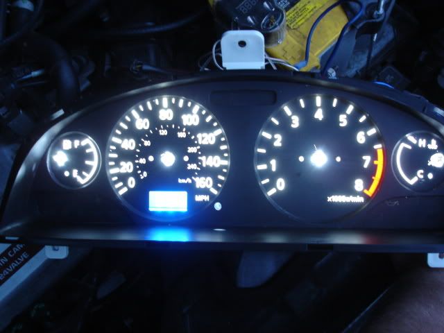
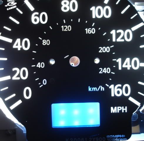
FINAL NOTES
Some things I did not note too well...I did not add anything behind the needles because I was out of blue PLCCs at the time...which sucks, because I really should have waited for them before I finished. Also, I did not take pictures of my of odometer array as I just kind of flew through it...but here are some pics as best I had...

PLEASE DO NOT SEND ME ANY PMS ABOUT THIS...KEEP ALL QUESTIONS IN THIS THREAD SO ALL CAN LEARN
Some things I did not note too well...I did not add anything behind the needles because I was out of blue PLCCs at the time...which sucks, because I really should have waited for them before I finished. Also, I did not take pictures of my of odometer array as I just kind of flew through it...but here are some pics as best I had...
PLEASE DO NOT SEND ME ANY PMS ABOUT THIS...KEEP ALL QUESTIONS IN THIS THREAD SO ALL CAN LEARN
Last edited by Metal Maxima; 09-29-2009 at 06:51 PM.

 06-23-2006, 10:45 AM
#12
Originally Posted by jeepik
rice rice baby
do you want people to see yuor face whe nyou are driving at night or something???
do you want people to see yuor face whe nyou are driving at night or something???
06-23-2006, 11:10 AM
#13
still brewin'

Join Date: May 2005
Location: MA, lost in GA
Posts: 317
I agree with Progress, they are abominably dim. Patience is key, hold your criticism until you see the finished product 
I love doing stuff on my own, but I solder just as well as I **** out my a$$. If you plan on making copies of the pre-fabbed disks, I'll buy a set.
BTW. any way some of the LEDs can be used for the clock/center console lights. two of my stupid little climate control twist in light bulbs are blown. $7.95 at my local dealer.
06-23-2006, 11:37 AM
#14
Originally Posted by jeepik
rice rice baby
do you want people to see yuor face whe nyou are driving at night or something???
do you want people to see yuor face whe nyou are driving at night or something???
06-23-2006, 11:50 AM
#15
Originally Posted by Progress
I'm guessing these will look kick-ass when sitting behind SE gauges. Probably almost electro-illuminescent.
Originally Posted by Progress
Dan, will you make and sell these?
06-23-2006, 11:52 AM
#16
Originally Posted by jeepik
rice rice baby
ALL interior lighting will be utilizing LEDs in the future, so I hope you enjoy buying circa 2005 and lower-year model cars the rest of your life.
06-23-2006, 11:54 AM
#17
Originally Posted by Yayomax
BTW. any way some of the LEDs can be used for the clock/center console lights. two of my stupid little climate control twist in light bulbs are blown. $7.95 at my local dealer.
You could also do this...

 06-23-2006, 12:38 PM
#18

Dam metal ive been asking you for awhile how it is u do the clear needles on our 5th gen i just need a quick run down of how you did it im pretty sure i can take it from dere im planinng on doing my gauges orange to match my interior but id like to know how the clear needles were done PLZ and Thank You LOL Oh yea great work on the gauges i look forward to see how urs turnout becuz im kinda doing it a bit differently but its about the same basic concept.
06-23-2006, 02:04 PM
#19
Originally Posted by Metal Maxima
Like Sam pointed out, by virtue of this argument this also makes all new Lexus, Honduhs, and Mercedes 'Rice'. :hsdan:
ALL interior lighting will be utilizing LEDs in the future, so I hope you enjoy buying circa 2005 and lower-year model cars the rest of your life.
ALL interior lighting will be utilizing LEDs in the future, so I hope you enjoy buying circa 2005 and lower-year model cars the rest of your life.
some how i doubt that the lexus gauges use this many LED's
no offense to the rest of you guys, they are guages, they dont need to be bright, look at the road and not at the guages ( my vision is not fantastic, but i can see my guages just fine at night)
i completely understand making these for show or for looks, but they have 0 practicality
06-23-2006, 02:36 PM
#20
still brewin'
Join Date: May 2005
Location: MA, lost in GA
Posts: 317
Originally Posted by jeepik
no offense to the rest of you guys, they are guages, they dont need to be bright, look at the road and not at the guages ( my vision is not fantastic, but i can see my guages just fine at night)
i completely understand making these for show or for looks, but they have 0 practicality
i completely understand making these for show or for looks, but they have 0 practicality
 06-23-2006, 03:04 PM
#22

not for anything but metal is doing something completely unique and is taking the time out as he goes along to take pictures and do a write up in case anyone else wants to do what hes doing in the future. whether you like his ideas or not, umm no one really cares. you cant take away the originality of the project. personally i think this is gonna look sweet as hell when its done and i wish i had the time and patience and skill to do something like this.
06-23-2006, 03:10 PM
#24
I do see your point. I may be wrong, but aren't the white face gauges in the 4th gen brighter than the titanium gauges in the 00-03
Thanks for the compliments fellas, I am going to try and make this a good how-to for all those interested.
 06-23-2006, 03:23 PM
#25
Originally Posted by Metal Maxima
Yep! Just use the OEM bulb holder, slide an LED through it, and bend the ends...attach a 510-ohm resistor to the negative side, twist in to contact, and enjoy.
You could also do this...
You could also do this...
Love this. Sex on wheels. Great job. Good luck on your project and future endevours.

 06-23-2006, 04:01 PM
#27
still brewin'
Join Date: May 2005
Location: MA, lost in GA
Posts: 317
Originally Posted by Metal Maxima
These require a fair amount of work to fabricate. More importantly...soldering everything is the EASY part. Gotta see how much work will be required to fit everything in the OEM housing.
Just a thought. That heat sink does look rather obtrusive. Ever consider using those small, flat 2" cooling fans usually found on a video card or computer PCB. They are 12-14 volts DC
06-23-2006, 06:23 PM
#28
Originally Posted by Yayomax
Just a thought. That heat sink does look rather obtrusive. Ever consider using those small, flat 2" cooling fans usually found on a video card or computer PCB. They are 12-14 volts DC
 While I sincerley appreciate the suggestion, the heatsink will be mounted outisde of the cluster. It's using a demel to allow the PCB to fit that is going to be the...uhmmm...interesting part.
  06-23-2006, 07:49 PM
#30
Originally Posted by jeepik
we're all on the same side here dude
So NO, we're not all on the same side here.

You want to make negative comments? Fine. KEEP IT OUT OF A HOW-TO THREAD.
06-23-2006, 09:33 PM
#31
Originally Posted by jeepik
wow cant take any critisism at all???
no need to get your panties in a wad!!!
we're all on the same side here dude
no need to get your panties in a wad!!!
we're all on the same side here dude
and if your making negative comments about someone trying to help everyone out by showing them how to make a decent mod to their car, then no, you arent on the same side as everyone else. keep the comments constructive or dont make any at all.
06-24-2006, 09:26 AM
#32
Originally Posted by 2k_MaXiMa_PiMpn
Dam metal ive been asking you for awhile how it is u do the clear needles on our 5th gen i just need a quick run down of how you did it im pretty sure i can take it from dere im planinng on doing my gauges orange to match my interior but id like to know how the clear needles were done PLZ and Thank You LOL Oh yea great work on the gauges i look forward to see how urs turnout becuz im kinda doing it a bit differently but its about the same basic concept.
06-24-2006, 03:00 PM
#33
Supporting Maxima.org Member
iTrader: (18)
Join Date: Nov 2004
Location: Springfield, MA
Posts: 1,570
Jeepik when you contribute something to maxima.org other than your ignorance, im sure dan would listen to you. But since he has about 20 how-to's on this forum....well heres how it is
Metal--->maxima guru
Jeepik---> noob
Metal--->maxima guru
Jeepik---> noob
06-24-2006, 03:29 PM
#34
Originally Posted by nismo0604
Metal--->maxima INTERIOR guru

Alright, well, looks as though I am not going to be able to get any updates in today.
 The missus and I are throwing a party tonight and I had to do alot more for it than I anticipated. HOWEVER, I have found a most interesting fact:
4th and 5th gen needles CANNOT be pulled straight out. 5.5 and AE cluster needles...PULL STRAIGHT OUT. I'll try and have updates as soon as possible, looks as though there are ALOT more LED 'easter eggs' in this cluster other than the gauges.
06-25-2006, 12:49 AM
#35
Originally Posted by nismo0604
Jeepik when you contribute something to maxima.org other than your ignorance, im sure dan would listen to you. But since he has about 20 how-to's on this forum....well heres how it is
Metal--->maxima guru
Jeepik---> noob
Metal--->maxima guru
Jeepik---> noob
06-25-2006, 01:07 PM
#36
Senior Member
iTrader: (3)

Join Date: Jan 2006
Location: Chicago,Bartlett,Ill Kolno, Polska
Posts: 1,431
Originally Posted by jeepik
you know what i'll take that as a compliment!!!
 06-26-2006, 12:00 PM
#37
when is comes down to it, why are you commenting that this mod is rice? if you really feel that way dont read or post comments in this thread and move on...if you come back and read/post more Metal wins....you are still reading his thread.
06-27-2006, 07:31 AM
#38
Seoul Man

Join Date: Jun 2004
Posts: 1,010
Originally Posted by jeepik
rice rice baby
do you want people to see yuor face whe nyou are driving at night or something???
do you want people to see yuor face whe nyou are driving at night or something???
06-27-2006, 07:51 AM
#39
Seoul Man
Join Date: Jun 2004
Posts: 1,010
Originally Posted by Yayomax
Just a thought. That heat sink does look rather obtrusive. Ever consider using those small, flat 2" cooling fans usually found on a video card or computer PCB. They are 12-14 volts DC
Whenever it is possible, I rip those tiny fans off my computer components and replace them with large passive heatsinks. Of course, that works for my computer because I have decent case airflow, so the big heatsinks are actually more effective than the original tiny heatsinks and fans. I don't know what it's like behind the gauge cluster.
06-28-2006, 01:40 AM
#40
still brewin'
Join Date: May 2005
Location: MA, lost in GA
Posts: 317
Originally Posted by spiromax
I've been working on computers for a very long time, and those tiny fans are the bane of my existence...and they tend to make a lot of noise without moving very much air.