
How to check ECU?????


 09-04-2006, 06:03 AM
#4
No, P1320 is when the ignition signal from the coils is not sent to the ECU during cranking, not the other way round. The P1320 is the DTC for bad coils so you should be testing those first and not trying to test or replace the ECU.
09-04-2006, 06:42 AM
#5
Member
Thread Starter

Join Date: Aug 2006
Posts: 71
Coils Coils Coils
Originally Posted by Puppetmaster
No, P1320 is when the ignition signal from the coils is not sent to the ECU during cranking, not the other way round. The P1320 is the DTC for bad coils so you should be testing those first and not trying to test or replace the ECU.
09-04-2006, 07:45 AM
#7
Member
Thread Starter
Join Date: Aug 2006
Posts: 71
Originally Posted by MacGarnicle
Well keep checking.. the ECU doesn't just die - and if it did there'd be more problems then a check engine light..
 09-04-2006, 10:04 AM
#11
Senior Member

Join Date: May 2004
Location: Vancouver, BC
Posts: 933
Check the connector on the Crankshaft Position Sensor (the one adjacent to the oil filter). Could be this sensor also. First thing....I would pull the connector, remove the sensor, clean the business end and reinstall.
09-04-2006, 04:56 PM
#13
Senior Member
Join Date: May 2004
Location: Vancouver, BC
Posts: 933
Are you sure about the cyl. no.s? Do you mean no spark all on either the rear bank or the front bank? The odd cylinders are at the firewall with no. 1 at the accessory/drive pulley end and the even cylinders are the front bank. How good is the spark? A good, fat, blue/whitish one or a thin, weak reddish one?
09-04-2006, 07:54 PM
#14
Member
Thread Starter
Join Date: Aug 2006
Posts: 71
Originally Posted by P. Samson
Are you sure about the cyl. no.s? Do you mean no spark all on either the rear bank or the front bank? The odd cylinders are at the firewall with no. 1 at the accessory/drive pulley end and the even cylinders are the front bank. How good is the spark? A good, fat, blue/whitish one or a thin, weak reddish one?
09-04-2006, 11:26 PM
#15
Senior Member
Join Date: May 2004
Location: Vancouver, BC
Posts: 933
Check the condenser. Pull the connector and check the condenser resistance. Should be more than a megaohmn. (The condenser is taped to the harness/raceway right behind the front camshaft cover towards the intake side.)
09-05-2006, 07:52 AM
#16
Member
Thread Starter
Join Date: Aug 2006
Posts: 71
Picture
Originally Posted by P. Samson
Check the condenser. Pull the connector and check the condenser resistance. Should be more than a megaohmn. (The condenser is taped to the harness/raceway right behind the front camshaft cover towards the intake side.)
09-05-2006, 08:58 AM
#17
Senior Member
Join Date: May 2004
Location: Vancouver, BC
Posts: 933
Locate the top row of attach bolts for the front camshaft cover. Right next to the second bolt from the left, taped (with clear tape) to the harness/raceway, is the condenser. It's about the size of your thumb.
09-05-2006, 09:19 AM
#18
Member
Thread Starter
Join Date: Aug 2006
Posts: 71
Originally Posted by P. Samson
Locate the top row of attach bolts for the front camshaft cover. Right next to the second bolt from the left, taped (with clear tape) to the harness/raceway, is the condenser. It's about the size of your thumb.
09-05-2006, 02:31 PM
#19

My original guess (as well as others) was ignition issue.. At least now we know that you are not getting spark...
First off F.Y.I. ----Firing order on our engines is 1-2-3-4-5-6.....my GUESS is that you have a sensor somewhere with 1/2 of it rusted or not sending a/c current.
Directly from alldata
NOTE: Unless you have someone who has a nissan specific scantool (dealership, certain specialized shops, and diy'ers who bought a hacked (legally) version off of the internet.), these codes will not show up as they are not emissions related and this shop will probably send you away or charge you hundreds of dollars in diag fees to pinpoint the problem. (doing pulse width, scope tests, reading schumatics, checking continuinity, etc.)
Knowing if you have one of these codes IS VITAL and will pinpoint your problem in seconds instead of hours. I.E. p0335 is a crankshaft position sensor (POS) fault, p1335 is POS REF signal fault, etc.)...
The problem is that you need to find out if your ecu is getting a signal from each of these sensors before following the flow chart. It is a waste of time pulling your ecu and testing continuinity to each of your coils before you first check to make sure your ecu is even suppossed to be sending a signal in the first place.
You wrote: [quote-StreetzINC]ps crank and camshaft sensors are functioning.[/quote]
How do you know this. Did you hook a scope to the sensor and check the graph. Or was it a pulse width test on a QUALITY multimeter? If it was a pulse width test are you sure you verified that the signal was not dropping to 0 for 1/2 of each revolution?
First off F.Y.I. ----Firing order on our engines is 1-2-3-4-5-6.....my GUESS is that you have a sensor somewhere with 1/2 of it rusted or not sending a/c current.
Directly from alldata
Originally Posted by Alldata
IGNITION COIL & POWER TRANSISTOR
The ignition signal from the ECM is sent to and amplified by the power transistor. The power transistor turns on and off the ignition coil primary circuit. This on-off operation induces the proper high voltage in the coil secondary circuit.
On Board Diagnosis Logic
Malfunction is detected when the ignition signal in the primary circuit is not sent to ECM during engine cranking or running.
Possible Cause
Harness or connectors (The ignition primary circuit is open or shorted. )
Power transistor unit built into ignition coil
Condenser
Crankshaft position sensor (REF)
Crankshaft position sensor (REF) circuit
DTC Confirmation Procedure
NOTE:
If "DTC Confirmation Procedure" has been previously conducted, always turn ignition switch "OFF" and wait at least 10 seconds before conducting the next test.
If DTC P1320 is displayed with DTC P0335, P0340, P1335 or P1336, perform trouble diagnosis for DTC P0335, P0340, P1335 or P1336 first.
Knowing if you have one of these codes IS VITAL and will pinpoint your problem in seconds instead of hours. I.E. p0335 is a crankshaft position sensor (POS) fault, p1335 is POS REF signal fault, etc.)...
The problem is that you need to find out if your ecu is getting a signal from each of these sensors before following the flow chart. It is a waste of time pulling your ecu and testing continuinity to each of your coils before you first check to make sure your ecu is even suppossed to be sending a signal in the first place.
You wrote: [quote-StreetzINC]ps crank and camshaft sensors are functioning.[/quote]
How do you know this. Did you hook a scope to the sensor and check the graph. Or was it a pulse width test on a QUALITY multimeter? If it was a pulse width test are you sure you verified that the signal was not dropping to 0 for 1/2 of each revolution?
09-05-2006, 02:35 PM
#20
ALSO:POSSIBLE CAUSES (LISTED ABOVE AS WELL)
Harness or connectors (The ignition primary circuit is open or shorted. )
I find this unlikely since there are 3 in a row (firing order) that are not firing.. I find it hard to beleive that 3 cylinders are shorted. (not all on the same bank)
Power transistor unit built into ignition coil
not likely at all
That leaves these three..... All three of these will throw a code accessible only to nissan specific scantools... 90% chance one of the following 3 are your problem..
Condenser
Crankshaft position sensor (REF)
Crankshaft position sensor (REF) circuit
09-05-2006, 02:42 PM
#21
Also you said you are getting spark from 1, 2 and 3....(your camshaft position sensor detects which cylinder you are on...)
If I didn't have a scantool this would be what I would check first.
Also note just because you graph a sensor and the sensor reads correct at the sensor, that doesn't necessarily mean that the ecu is reading the sensor correct. (high resistance fault in anywire to/from ecu, etc.)
I'm curious as to how you decided those sensors are functioning. I would check for signal at the correct terminals at the ecu if it where me.
(Not just a signal, but the signal has to be functioning as a permanent marnet signal should be... I.E. One high signal indicating cylinder #1 then 5 medium signals with drop offs inbetween. Then one high signal for #1 again, then 5 low....etc,etc,etc.)
09-05-2006, 03:59 PM
#22
Ok, now what did you do to turn this...........
and this
into this...
Whatever you did, you may be on the right track.
Originally Posted by StreetzINC
Yeah i have a check engine light(P1320), no signal from ecu wire to coil packs, and the car is not starting up.
Originally Posted by StreetzINC
Tell me what more problems i will have???? My car isnt cranking, not one of the spark plugs are getting spark.....
into this...
Originally Posted by StreetzINC
Ok now i am getting spark from cylinders 1,2, and 3. But no spark signal from 4,5, and 6. What is up with that????
Whatever you did, you may be on the right track.
09-05-2006, 04:15 PM
#23
Senior Member
Join Date: May 2004
Location: Vancouver, BC
Posts: 933
The easiest thing right now is to check the condenser if you a have multimeter/ohmeter. The resistance should be HIGH if the condenser is good. If it is low, chuck it. Above you said that you had a weak spark on at least three cylinders. Condensers are notorious when failing for causing a weak spark. The condenser (a capacitor) is in the primary ignition circuit and it is this primary voltage which is used by each coil to develop the secondary high tension voltage for the spark plugs. Capacitors hold/build up voltage then quicky discharge it. Go for the simple things first. It is unlikely that it is the ECM, and the crank pos. sensors and the like are simple, have no moving parts and rarely fail. As mentioned above, check all the connectors associated with the ignition system that you can find, including the one on the Crank Pos. Sensor. I would remove it, make sure that it is clean, and reinstall it. It is sometimes quite oily down there.
09-05-2006, 04:38 PM
#24
Originally Posted by P. Samson
Condensers are notorious when failing for causing a weak spark. The condenser (a capacitor) is in the primary ignition circuit and it is this primary voltage which is used by each coil to develop the secondary high tension voltage for the spark plugs. Capacitors hold/build up voltage then quicky discharge it.
The way I understood it is that 12v high amps went to the primary coil windings. When the coil collapsed (ecu took away the ground) magnetic induction turned this energy into high volts low amps calculated by the amount of windings in each coil.
Anyhow, I don't want to get off subject so if you know of an article or something that explains where these condensors are located (and exactly how they work) I would appreciate it.
09-05-2006, 05:09 PM
#25
Senior Member
Join Date: May 2004
Location: Vancouver, BC
Posts: 933
Sorry, the ONE capacitor/condenser is in the coil power supply circuit, not the primary circuit as I stated above. Per FSM (Euro) EC Page 371/372. And.......I did not mean to imply that this condenser was generating the secondary high tension voltage. (da spark) After having looked at the FSM, the other possibility is a fault with the ECM relay relating to the coil power supply circuit. There are a couple of troubleshooting checks dealing with this relay.
09-05-2006, 05:59 PM
#26
Member
Thread Starter
Join Date: Aug 2006
Posts: 71
Originally Posted by P. Samson
Sorry, the ONE capacitor/condenser is in the coil power supply circuit, not the primary circuit as I stated above. Per FSM (Euro) EC Page 371/372. And.......I did not mean to imply that this condenser was generating the secondary high tension voltage. (da spark) After having looked at the FSM, the other possibility is a fault with the ECM relay relating to the coil power supply circuit. There are a couple of troubleshooting checks dealing with this relay.
09-05-2006, 06:49 PM
#27
Senior Member
Join Date: May 2004
Location: Vancouver, BC
Posts: 933
The relay is in the elect. box in front of the battery. It is labelled. Do you have a multi-meter? Without one you are kinda screwed. One thing you can do is check the ground for coil power circuit. There are four grounds I think(one is the ground for this circuit) beside the oil filler. Loosen them off, check for corrosion and retighten.
09-05-2006, 07:15 PM
#28
Member
Thread Starter
Join Date: Aug 2006
Posts: 71
Originally Posted by P. Samson
The relay is in the elect. box in front of the battery. It is labelled. Do you have a multi-meter? Without one you are kinda screwed. One thing you can do is check the ground for coil power circuit. There are four grounds I think(one is the ground for this circuit) beside the oil filler. Loosen them off, check for corrosion and retighten.
09-05-2006, 07:28 PM
#29
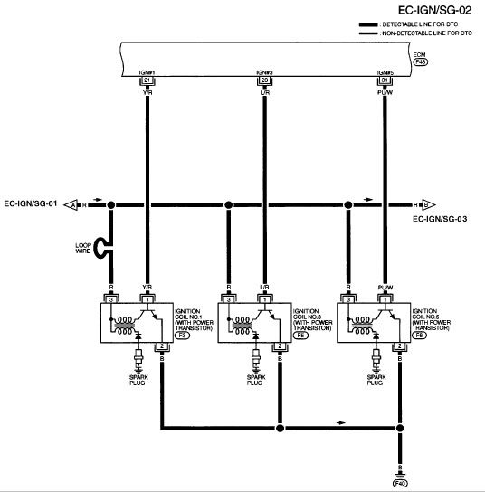
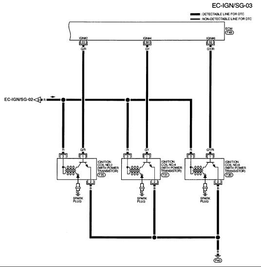
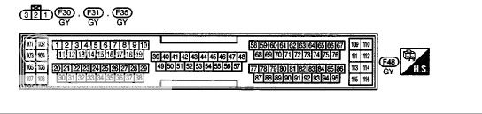
ok. Here are some diagrams..
I checked the connector F40. (located in f2 of the second to bottm picture posted) It is an engine ground on the passanger side of the motor. Looks to be near the top. The arrows are using the conventional flow theory. F34 in ign01 (the first one where f34 is next to the "condensor" is located) is located in d2 on the picture second to last.....Anyhow, This is the best I can do for you. Good luck.
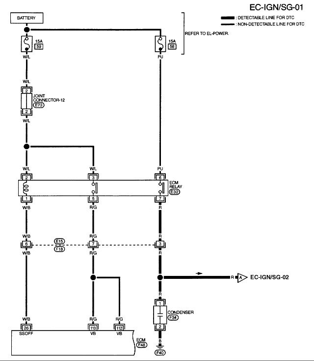
connector for ign 01
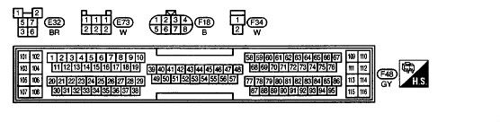
connector for ign 02
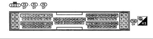
I checked the connector F40. (located in f2 of the second to bottm picture posted) It is an engine ground on the passanger side of the motor. Looks to be near the top. The arrows are using the conventional flow theory. F34 in ign01 (the first one where f34 is next to the "condensor" is located) is located in d2 on the picture second to last.....Anyhow, This is the best I can do for you. Good luck.
connector for ign 01
connector for ign 02
 09-05-2006, 07:53 PM
#32
Senior Member
Join Date: May 2004
Location: Vancouver, BC
Posts: 933
http://jime.homeip.net/files/FSM/. This address for the Euro spec. FSM seems to be working again. Depending on your ISP speed you could try downloading the 2000 FSM in less than an hour. Then you've got all the info. Otherwise this is too tedius. Section EC pages 368 and subsequent is where you need to be.
09-05-2006, 07:56 PM
#33
Member
Thread Starter
Join Date: Aug 2006
Posts: 71
Originally Posted by P. Samson
FIRST: With the Ign. OFF remove the connector from the condenser. With Ign. ON, check DC VOLTS between the harness connector terminal 1 and ground. Should read about 12 volts. Does it?
09-05-2006, 08:21 PM
#34
Member
Thread Starter
Join Date: Aug 2006
Posts: 71
Originally Posted by P. Samson
FIRST: With the Ign. OFF remove the connector from the condenser. With Ign. ON, check DC VOLTS between the harness connector terminal 1 and ground. Should read about 12 volts. Does it?
09-05-2006, 08:54 PM
#35
Senior Member
Join Date: May 2004
Location: Vancouver, BC
Posts: 933
That's perfect. Ign. OFF. Now with the ohmeter check the harness connector terminal 2 to a clean spot on the engine. Should have no resistance. This checks the circuit ground. Why your're at it, check between the two terminals on the condenser. With the ohmeter set to a high range, check that it has high resistance. More than the one Megaohm that I mentioned earlier. (Your meter will probably have a 1 or 2M and a 10M selection at the high end.) Jeez.....it's almost 01:00 your time!! WAIT!! I misread your previous terminal figures. You got the 11.91 at terminal 2?? That is a one piece connector on the condenser??
09-05-2006, 09:35 PM
#36
Member
Thread Starter
Join Date: Aug 2006
Posts: 71
Originally Posted by P. Samson
That's perfect. Ign. OFF. Now with the ohmeter check the harness connector terminal 2 to a clean spot on the engine. Should have no resistance. This checks the circuit ground. Why your're at it, check between the two terminals on the condenser. With the ohmeter set to a high range, check that it has high resistance. More than the one Megaohm that I mentioned earlier. (Your meter will probably have a 1 or 2M and a 10M selection at the high end.) Jeez.....it's almost 01:00 your time!! WAIT!! I misread your previous terminal figures. You got the 11.91 at terminal 2?? That is a one piece connector on the condenser??
09-05-2006, 10:12 PM
#37
Senior Member
Join Date: May 2004
Location: Vancouver, BC
Posts: 933
The battery voltage should be at condenser harness connector terminal 1. I can't see how you have it at terminal 2. Terminal 2 should be to ground. I didn't twig on the fact that you've got a '98. The next quick and dirty swap try could be the ECM relay. Check the terminals........if the same, try the swap. Same for the Crank Pos. Sensor (by the oil filter). Just make sure they have the same "business end" length/protrusion etc. Your condenser resistance reading confuses me but it shouldn't prevent a startup by the sound of it. When you're disconnecting/connectiong things just make sure the ignition is OFF! I'm going for coffee and to see if Leno is live tonight!
09-05-2006, 10:17 PM
#38
Member
Thread Starter
Join Date: Aug 2006
Posts: 71
Originally Posted by P. Samson
The battery voltage should be at condenser harness connector terminal 1. I can't see how you have it at terminal 2. Terminal 2 should be to ground. I didn't twig on the fact that you've got a '98. The next quick and dirty swap try could be the ECM relay. Check the terminals........if the same, try the swap. Same for the Crank Pos. Sensor (by the oil filter). Just make sure they have the same "business end" length/protrusion etc. Your condenser resistance reading confuses me but it shouldn't prevent a startup by the sound of it. When you're disconnecting/connectiong things just make sure the ignition is OFF! I'm going for coffee and to see if Leno is live tonight!
09-06-2006, 01:45 PM
#39
Member
Thread Starter
Join Date: Aug 2006
Posts: 71
So today i switched cam sensor on my 98 max with the 2000. The 98 started up fine with the 2000 camshaft sensor. Then i went to the crankshaft sensor on the transmission not the one by the oil pan they looked a little different the 98 crankshaft sensor looks bigger but the 2000 crankshaft sensor fit on the 98 and tried to crank the 98 it didn't start with the 2000 crankshaft sensor. So i took the 98 sensor and put it on the 2000 it lined up but the car still didnt start. Still got the same result as before with the original sensor. I put the sensors back on the correct cars and the 98 cranked up fine, but the 2000 has the same result. Does this mean anything?????
09-06-2006, 04:35 PM
#40
Senior Member
Join Date: May 2004
Location: Vancouver, BC
Posts: 933
The Crank Pos. Sensor and/or the circuit that could be the problem is the one under the accessory drive pulley. It was different than your '98s?? If they are different then swapping them would be a moot point. Did you think about "obtaining" the FSM copy? It would be far easier troubleshooting etc. for you now and probably in the future.