
Front bearing Replacement (Write up, Archives)


Thread Starter
Supporting Maxima.org Member

Joined: Feb 2007
Posts: 157
From: Montr�al, Qc, Canada
Front wheel bearings replacement instructions
Ok girls, I just manage to do both of my front bearings (Quebec car operating in salt and snow, tons of rust)
Here is my write up on what to do.
You will need:
1- Preparation
Jack the car on a leveled surface, secure the car with jack stands. Put the hand brake. Safety first!
Remove the wheel.
2- Spindle/knuckle Assy removal.
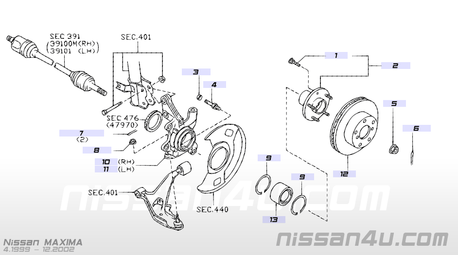
Fig 1
All steps required to reassemble are pretty easy if you succeeded into the dismantling portion. Here are a few areas you should put special care in.
Hopefully this information will be handy. And I am very sorry if the level of english used for this article is not optimal, it is not my mother tongue.
Olivier
Here is my write up on what to do.
You will need:
Parts(Qty per side)
Circlip 4021405U00 Qty 2
Bearing 402102Y000 Qty 1
Ball Joint Nut 0122500581 Qty 1 (Better replacing them)
Ball Joint Cotterpin 089213202A Qty 1
Tie Rod end Nut 0122700081 Qty 1
Tie Rod end cotterpin 089213252A Qty 1
Tools:
Sockets:
14 mm
17 mm
19 mm
21 mm (Wheels)
32 mm (Axle nut)
Others
� drive breaker bar and 3 foot tube to act as an extension
1/8 drill bit and drill
Cutting pliers
3 legs puller (if you don�t have this, go and buy one)
Bearing separator
4 lb sledge hammer
2 inch tow ball (10$ in any car parts store)
Vice well fixed to a working bench
Dremel and thin cutting disc
Long nose pliers
1- Preparation
Jack the car on a leveled surface, secure the car with jack stands. Put the hand brake. Safety first!
Remove the wheel.
2- Spindle/knuckle Assy removal.
Fig 1
2.1 � Axle nut removal (Fig 1, Item 5)
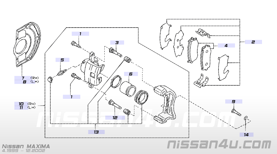
Fig2
a) Remove both caliper bolts 14 mm (Item 1 , Fig 2)
b) Remove Caliper and use a bungee cord to hang it to the coil spring so you don�t damage the brake line.
c) Remove both Caliper bracket bolts (Item 9, Fig 2)
d) Remove Caliper bracket (try to leave the pads on, or change them in the mean time.)
e) Remove Brake disc.
Note:
- If disc is stuck, use a rubber hammer. If it does not come off, there are probably 2 threaded holes between the lug nuts. By using bolts and tightening them into the holes, this will act as a puller and the disc should come off.
a) Remove cutter pin from axle. If it is jammed, use the cutting pliers, cut it as close to the threads as possible. Use the drill and the 1/8 drill bit to clean the hole.
b) Ask your girl friend to hold the brakes firmly, so the spindle cant rotate anymore.
c) Using the breaker bar, the 32mm box and your 3 feet extension tube, break loose the axle nut. It is standard threaded, so counterclockwise motion is required to loosen it up.
Notes:
- Apply force by lifting the bar instead of putting your weight down. I usually find it safer and more efficient this way.
- Forget about usual 1/2 impact drives, they are usually to weak for this operation.
2.2 Remove Brake systemb) Ask your girl friend to hold the brakes firmly, so the spindle cant rotate anymore.
c) Using the breaker bar, the 32mm box and your 3 feet extension tube, break loose the axle nut. It is standard threaded, so counterclockwise motion is required to loosen it up.
Notes:
- Apply force by lifting the bar instead of putting your weight down. I usually find it safer and more efficient this way.
- Forget about usual 1/2 impact drives, they are usually to weak for this operation.
Fig2
a) Remove both caliper bolts 14 mm (Item 1 , Fig 2)
b) Remove Caliper and use a bungee cord to hang it to the coil spring so you don�t damage the brake line.
c) Remove both Caliper bracket bolts (Item 9, Fig 2)
d) Remove Caliper bracket (try to leave the pads on, or change them in the mean time.)
e) Remove Brake disc.
Note:
- If disc is stuck, use a rubber hammer. If it does not come off, there are probably 2 threaded holes between the lug nuts. By using bolts and tightening them into the holes, this will act as a puller and the disc should come off.
2.3 Free the axle to access the ball joint.
(I proceed this way so I get better access to the ball joint nut, mine was all rusted.)
3 Bearing Removal.(I proceed this way so I get better access to the ball joint nut, mine was all rusted.)
a) Remove the tie rod end lock nut cotterpin , if it is stuck, use same technique as for the axle nut cotterpin. Make sure the threads are clean and free of any material left from cotterpin removal.
b) Remove tie rod end nut
c) Remove tie rod end from knuckle (item10 and 11, Fig 1) by hammering the knuckle material that is around the tie rod end. While hammering, keep a pressure on the tie rod end threaded part where the nut was. This will ensure that the tie rod will escape its position as soon as it is free.
d) Disconnect the ABS Sensor from under the hood; detach the wire from the shock strut. Note:
- I suggest you leave the sensor in place so you don�t damage it trying to remove it. Mine was rusted in place.
e) Remove the two shock strut bolts (Identified as Sec.401 in fig 1)
f) Pull the knuckle out of the axle. You now have access to the ball joint nut.
2.4 Ball joint removal b) Remove tie rod end nut
c) Remove tie rod end from knuckle (item10 and 11, Fig 1) by hammering the knuckle material that is around the tie rod end. While hammering, keep a pressure on the tie rod end threaded part where the nut was. This will ensure that the tie rod will escape its position as soon as it is free.
d) Disconnect the ABS Sensor from under the hood; detach the wire from the shock strut. Note:
- I suggest you leave the sensor in place so you don�t damage it trying to remove it. Mine was rusted in place.
e) Remove the two shock strut bolts (Identified as Sec.401 in fig 1)
f) Pull the knuckle out of the axle. You now have access to the ball joint nut.
a) Remove the cotter pin. (Item 7, Fig 1) Again with the same technique as for the axle cotterpin and by putting special care to the quality of the threads.
Note:
- If the threads are damaged, there are risks of jamming the nut while loosening it. The nut will then engage the ball joint in a rotating motion. The only way of removing the nut is then to cut/grind it off, you don�t want this, believe me.
b) Remove the ball joint nut (Item 8, Fig 1)
c) Re-attach the knuckle to the shock temporarily uning two shock strut bolts (Identified as Sec.401 in fig 1)
d) Using a floor jack, lift the suspension by the spindle (Item #2 , Fig 1) You don�t need to lift that much, it is only to allow the lower control arm to fall loose.
e) Using the same technique as for the tie rod removal from the knuckle, hammer the knuckle around the ball joint.
Note:
- Quite a bit of hammering force is required; you may try with the sledge hammer. Be careful not to damage the ball joint boot.
f) Once the lower control arm falls off, remove the two temporary installed strut bolts.
The Spindle/Knuckle assy is free.
Note:
- If the threads are damaged, there are risks of jamming the nut while loosening it. The nut will then engage the ball joint in a rotating motion. The only way of removing the nut is then to cut/grind it off, you don�t want this, believe me.
b) Remove the ball joint nut (Item 8, Fig 1)
c) Re-attach the knuckle to the shock temporarily uning two shock strut bolts (Identified as Sec.401 in fig 1)
d) Using a floor jack, lift the suspension by the spindle (Item #2 , Fig 1) You don�t need to lift that much, it is only to allow the lower control arm to fall loose.
e) Using the same technique as for the tie rod removal from the knuckle, hammer the knuckle around the ball joint.
Note:
- Quite a bit of hammering force is required; you may try with the sledge hammer. Be careful not to damage the ball joint boot.
f) Once the lower control arm falls off, remove the two temporary installed strut bolts.
The Spindle/Knuckle assy is free.
3.1 Spindle Removal
a) Secure the knuckle into the vice by the section that was attached to the strut. The lug nuts need to face down.
b) Using the 32 mm socket (mine was the perfect dimension) and the rubber hammer, punch out the spindle from the bearing.
Note:
- Be careful not to drop the spindle on the floor when it comes off the bearing.
c) Remove the bearing race dust guard (thin metal piece) stuck on the spindle shaft using the flat screw driver (don�t worry to damage it, we will not reuse this part)
d) Remove the bearing race by squeezing the bearing puller between the race and the spindle. Tighten it moderately, just enough so it does not lose grip while pulling on it with the 3 legs puller.

e) Remove the bearing race with the pullers by creating an installation with the pullers similar to this one.

b) Using the 32 mm socket (mine was the perfect dimension) and the rubber hammer, punch out the spindle from the bearing.
Note:
- Be careful not to drop the spindle on the floor when it comes off the bearing.
c) Remove the bearing race dust guard (thin metal piece) stuck on the spindle shaft using the flat screw driver (don�t worry to damage it, we will not reuse this part)
d) Remove the bearing race by squeezing the bearing puller between the race and the spindle. Tighten it moderately, just enough so it does not lose grip while pulling on it with the 3 legs puller.
e) Remove the bearing race with the pullers by creating an installation with the pullers similar to this one.
3.3 Bearing cir-clip removal from knucle (Hardest part when you don�t know how)
4 Reassembly of the knuckle assya) The cir-clips installed from factory do not have a notch to easily remove them.
Change the orientation of the Knuckle in your vice in order to have the wheel side facing up. The cir-clip on this side is more accessible.
b) Using the dremel and the cutting disc create a groove into the cir-clip near one end. Do not worry about lightly damaging the knuckle. There is plenty of surface to support the future new cir-clip.
c) With a flat screwdriver, pry the cir-clip outside its slot.
d) Hold the cir-clip in place,
Note:
- I used a screwdriver shaped as a needle and stuck it behind the cir-clip.
e) Create another groove with the dremel and pry the circlip further out.
f) It will eventually be easy to remove the cir-clip.
3.4 Pressing the bearing out.Change the orientation of the Knuckle in your vice in order to have the wheel side facing up. The cir-clip on this side is more accessible.
b) Using the dremel and the cutting disc create a groove into the cir-clip near one end. Do not worry about lightly damaging the knuckle. There is plenty of surface to support the future new cir-clip.
c) With a flat screwdriver, pry the cir-clip outside its slot.
d) Hold the cir-clip in place,
Note:
- I used a screwdriver shaped as a needle and stuck it behind the cir-clip.
e) Create another groove with the dremel and pry the circlip further out.
f) It will eventually be easy to remove the cir-clip.
a) Turn the knuckle in the vice so the wheel side faces downwards. Firmly, and I mean very firmly tight the vice on the knuckle section that attaches to the shock strut.
b) Take the Tow Ball and the sledge hammer.
Note:
- I found safer to position the Tow ball nut flush with the Tow Ball stud in order to give a bigger hammering area. The next part is scary, better wear big gloves.
c) Put the Ball part of the Tow Ball against the bearing. The ball will center itself inside the inner portion of the bearing.
d) With the sledge hammer, aim for the stud of the tow ball and not your fingers!
e) The bearing will slowly start its way down.
f) You can remove the other cir-clip, but I had such a hard time for the first one and seeing how solid it was, the remaining cir-clip will certainly do the job for years. I suggest leaving it there.
4.1 Press new bearing in
Note:
- Because you see what happened to the bearing inner race stuck on the spindle shaft, you understand that we need to take precaution when pressing the spindle in place to prevent the bearing from splitting.
5 Reassembly of the knuckle onto the car.a) Rotate the knuckle in the vice so the wheel side is facing up.
b) Take the old bearing, grind the first half inch of its outer surface all around. This will avoid the old bearing from jamming when completing the pressing of the new one.
c) Clean the bearing bore inside the knuckle.
d) Position the new bearing in the hole (bearing does not have a specific rotation direction)
e) With the old bearing placed on top of the new one (Make sure the grinded area is correctly positioned in order to prevent this old bearing from jamming in the bore)
f) With the sledge hammer and the tow ball, punch the new bearing in place.
4.2 Cir-clip installationb) Take the old bearing, grind the first half inch of its outer surface all around. This will avoid the old bearing from jamming when completing the pressing of the new one.
c) Clean the bearing bore inside the knuckle.
d) Position the new bearing in the hole (bearing does not have a specific rotation direction)
e) With the old bearing placed on top of the new one (Make sure the grinded area is correctly positioned in order to prevent this old bearing from jamming in the bore)
f) With the sledge hammer and the tow ball, punch the new bearing in place.
a) The new cir-clips do have notches to install and remove them. A pair of long nose pliers is sufficient for the installation.
4.3 Spindle installationNote:
- Because you see what happened to the bearing inner race stuck on the spindle shaft, you understand that we need to take precaution when pressing the spindle in place to prevent the bearing from splitting.
a) Place your 32mm socket on the garage floor. Put the spindle on top of it with the shaft facing up, make sure the wheel studs are not in contact with the floor.
b) Position the knuckle/bearing.
c) Use the tow ball and sledge hammer.
Notes:
- It takes less energy to press the spindle in place than it took for the bearing, be gentle with the hammer not to damage the new bearing.
- Rotate the bearing once in a while between two hammering sessions to prevent the bearing from being damaged.
- You don�t have to press it all the way in, just enough so the axle nut will be able to catch a few threads.
All steps required to reassemble are pretty easy if you succeeded into the dismantling portion. Here are a few areas you should put special care in.
5.1 Ball Joint Nut installation
a) Install temporarily the shock strut to the knuckle using its nuts. Locate the ball joint into the knuckle and use your floor jack to lift the suspension by the lower control arm, not by the spindle as previously mentioned. This will jam the ball joint in place and allow you to tight it.5.2 Axle nut tightening.
Et Voil�!a) Install temporarily the shock strut to the knuckle using its nuts. Locate the ball joint into the knuckle and use your floor jack to lift the suspension by the lower control arm, not by the spindle as previously mentioned. This will jam the ball joint in place and allow you to tight it.
a) Rotate the spindle assembly a few times while tightening the nut to avoid bearing damage.
Notes:
- Use anti-seize on all bolts and nuts
Notes:
- Use anti-seize on all bolts and nuts
Hopefully this information will be handy. And I am very sorry if the level of english used for this article is not optimal, it is not my mother tongue.
Olivier
Last edited by ColtMax; Jan 29, 2010 at 05:17 AM.

Superb writeup! I am still for hire, if anyone is too lazy or afraid to do this on their own.
http://forums.maxima.org/southeast-u...-bearings.html
http://forums.maxima.org/southeast-u...-bearings.html

Thread Starter
Supporting Maxima.org Member
Joined: Feb 2007
Posts: 157
From: Montr�al, Qc, Canada
Passenger's side was done the same way as this side, all steps are exactely the same.
I just want to add a little note about the Ball Joint nut.
It is very very hard to break loose, I had to use the breaker bar and the 3 foot extention tube.
Thanks for the comments!
I am replacing a rear wheel bearing this week, ill do a write up about it with pictures this time.
I just want to add a little note about the Ball Joint nut.
It is very very hard to break loose, I had to use the breaker bar and the 3 foot extention tube.
Thanks for the comments!
I am replacing a rear wheel bearing this week, ill do a write up about it with pictures this time.

Great instructions. I for one can appreciate someone who takes the time to document a task down to the tittle & publish for the world to see, when its only purpose is to help others.
One small comment, since I see you linked to a Great Neck breaker bar.
I had my trusty AutoZone Great Neck breaker bar when I replaced my control arms & it failed me. This breaker bar had gotten me through struts without a problem, but once I took on the axle nut, it couldn't handle it and it broke. Bought a Craftsman after that.
May or may not apply to everyone, but a decent breaker bar is necessary for cracking that axle nut loose, especially if it's never been touched.
Last edited by ridinwitha35; Jan 31, 2010 at 06:14 PM.

Thread
Thread Starter
Forum
Replies
Last Post
FanaticMadMax
5th Generation Maxima (2000-2003)
7
Aug 10, 2015 08:55 PM
laparka66
7th Generation Maxima (2009-2015)
16
Aug 6, 2015 09:36 AM