
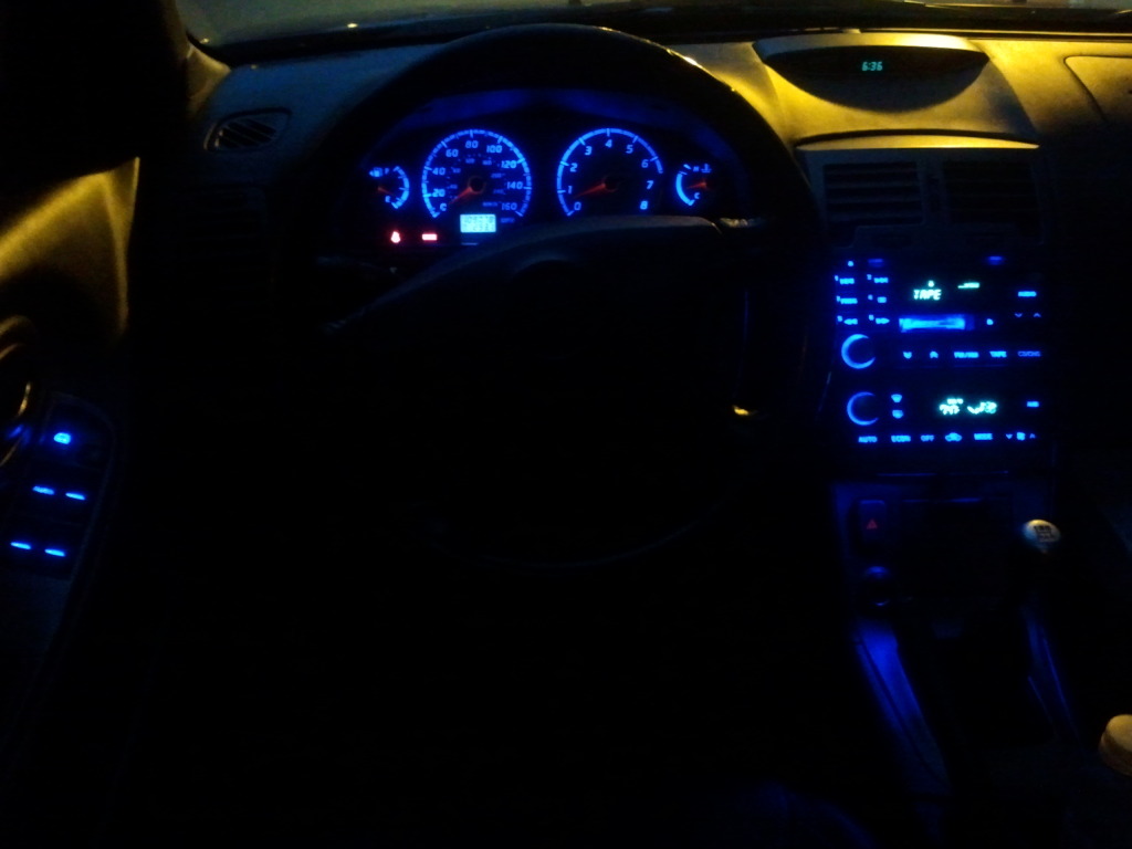
interior LEDs


interior LEDs
I attempted to hook up some small 3mm LEDs on my interior for some mood lighting and when i wired them up the LEDs blew out. So im assuming that i need some resistors. Now i know some of you guys have much experience with this and i am not sure what size resistors that i will need to make these work. Anyone have any input?? thanks.

you need to get info on the leds first. you need to know the voltage drop and how many milliamps they put out. then go on google and type led resistor calculator and punch in the info. you also need the voltage which is powering the led which is obviously 14 volts from the battery.


I have a question since I plan on doing this tomorrow. When I LED the radio tomorrow do I need fast switching diode's for the short lead's (-) and resistors for the long lead's (+) or can I get away with just using resistors on the one lead (+)?
you don't need a fast switching diode on each LED...the best way is to figure out the power and ground at the connector and splice in at that point. That way you only use ONE resistor and one diode. Much cleaner that way
 I can't tell you which ones are which though, as the design of the radio faces likely changed over time...you'll have to figure which is which...it's not that hard, just get yourself a DMM
you're going to have to figure out the best value resistor for what you want to do...

How many bulbs are we talking about?
It's not usually a good idea to use more than 1 resistor per 3 LED's, I don't know the reasoning, but I think it has something to do with voltage drop multiplication. ie. if you put 6 LED's on there with a 3k OHM resistor (proper size according to basic math), then the last 2 LED's won't even light up.
I don't know a ton about this, again, but I'd advise you do either 1 resistor per LED or 1 per 3 LED's, but not more than that.

Here's a pic I found, this guy put resisters on all the LED's.. Is that no good or what? Which ever way is more simple, that's the direction I need to head. lol
http://i1104.photobucket.com/albums/...0/IMG_3396.jpg
Thanks for your help.
http://i1104.photobucket.com/albums/...0/IMG_3396.jpg
Thanks for your help.
eww.
When I did MY radio, I did one resistor per LED, and the resistor was mounted behind...not in front liike your pic shows. I didn't bother with the diode though.
When I looked at Galactica's radio, there was the diode and two resistors, as he mentioned. The install on that was a lot cleaner, but still a PITA since your'e not swapping LEDs for LEDs.
")
I've almost always done 1 resistor per LED. Unless you know or have a good way to test (like Americaner does) the imput Negative and Positive from the illumination circuit.
IMO, all that is just extra time/work. It's less work to put a resistor on each LED, and this is especially true if you're just an 'average joe', not "super-electrician dude".
1 Resistor per LED, call it a day. And yes, mount them on the backside of that Circuit board, because that picture is a good example of a messy, dangerous way to do it.
As for the fast switching diode, I've never done it either until Shinjiduo informed me about it and it's benefits.
Honestly, it's not really necessary unless you're working with trash LED's. Good LED's with 560 Ohm resistors will be fine for the rest of the time you have the car (most likely) as long as you wire them in properly and cleanly.
I'm not saying DON'T install them, YOU SHOULD do it, I'm just saying I never have.
If you are planning to keep the car for some time, it's worth doing, because the LED's WILL DIM OVER TIME if you don't install these.
Here's some pictures I took, this came off my 02' Max.. Sorry for the bad pictures. So I'm almost ready for install, just waiting to get these magnified glasses so I can see a little better.
So looking at the rear side (pic 2,3) of the electrical board, on each side of the neo looking platform, there is u shaped solder that looks like its holding a small clip sticking out on the base. I'm amusing that I would head up the u-shaped solder while using some soldering braid to remove it from the board correct? If this is wrong please let me know, thanks.
Also I will be using 1/8 watt 470 ohm resisters with the 360 5mm super white LED's from superbrightleds.com (RL5-W45)..


The pictures are blurry/low quality, but to me it looks like that black piece is the 'base' that holds the bulb.
The bulb 'contacts/probes' are similar to an LED's, just more flexible, like thin wire. All you need to do is warm up the solder contact on the backside of the board where the 'contact wire' from the bulb connects, and pull the wire out with tweezers or something.
Do this for both wires, then yu should be able to simply pull the bulb right out from the base. Then Install your LED in it's place with a resistor.
 Truth
TruthHmm... I think the 5mm 360's I have are gonna be to big to fit on that base.. That's why I was thinking of just removing the whole base and then soldering the LED with resister. I'm no expert, I guess I will find out soon lol. I also have 3mm LED's that I could use but I bought the 5mm 360 because someone on the forums said it works on the radio.
You don't need ot use the base, you're right it's probably better ot just get rid of it.
OK sweet, I have one more important question. When I was analyzing the rear part of the board, holding it in the upright position, it looks like the leads North of the base are all negative(-) and on the south end of the base's are all positive(+). It looks like they all trace back to the main plug where (ILL)- and (ILL+) are.
So basically I would just make sure of that and add resisters on the positive+ correct? There are also small numbers at the south end of each base reading something like PL258 where I believe the positive leads are.
Also there is a light in the power button/Volume, does this just pop off? I tried prying it off lightly but didn't want to break anything.
Thanks Tuner and everyone else for the help and excuse my ****ty photography up above^
I haven't done those audio units so unfortunately Im not much help with the specifics, I can only work with those pictures. Maybe americaner or someone can help more.
The ***** are super tight but should pop off IIRC, unless that one is different. I have no idea if it's lit, may be aprism from a bulb somewhere else close (piece of clear acrylic-like plastic)
And it doesnt matter which side you puy the resistor on.
The ***** are super tight but should pop off IIRC, unless that one is different. I have no idea if it's lit, may be aprism from a bulb somewhere else close (piece of clear acrylic-like plastic)
And it doesnt matter which side you puy the resistor on.
Well, my LED progress is comin along but slowly. I couldn't quite figure out where to splice in the one resister for all the LEDs in the radio cluster so I've just been doing each LED with a resister.
Also I still haven't figured out how to remove the volume **** so I can LED it, I've tried pulling and prying with a decent amount of force and still no luck.
As far as the climate control goes, its all done and working but there are some hot spots. Could I just use a black sharpie to touch the LED up a bit or how would I go about fixing hot spots?
Thanks again. I'll post pics soon
Hotspotting can sometimes be as simple as turning an led a bit. Or adding a light tint to a portion of the illuminated area, sometimes you need to use more leds. There's no simple answer because every application is different. Sometimes its close to unavoidable, our simply unreasonable
Last edited by TunerMaxima3000; Oct 7, 2012 at 02:54 PM.
Are the hotspots for the backlighting? Or the indicators? If backlighting, replace with 360* LEDs. IF it's just hella bright, then use the brush-type white out and cover the LED face to dim it a bit.