View Poll Results: 5th Gen LED mod thread, Yepe or Nepe?
I'd read it, maybe even subscribe to it, but I'd never actually have the balls to do it on my car


15.22%


I've already done it, but would like to contribute my experience and technique to this thread


15.22%
Voters: 46. You may not vote on this poll
How to LED your 5th gen _~ Feeler thread .w. POLL
 01-20-2012, 10:13 PM
#1
Senior Member
Thread Starter
iTrader: (4)
Join Date: Jul 2006
Location: Ontario, Canada
Posts: 5,548
How to LED your 5th gen _~ Feeler thread .w. POLL
Do you guys want this? I've decided that I'm not going to pursue LED mods for anyone but myself anymore unless the money is large enough and I have the spare time available.
This means all the little tricks I have stored can be yours, since this forum has helped me on so many levels. However, this would require a ton of new photos, and me asking for consent from some previous customers, etc.
I realize it's a little silly to post a thread just to ask this, but if you understood the work that will go into a "how to LED mod your 5th gen" thread from me, then you'd understand why I'm asking first.
Please be honest, I don't want to do this for one or two guys that will actually use it. I don't have the spare time for that, I can do that via PM.
Also, please note that I WILL NOT be including tedious things like "how to solder", how to remove your gauge cluster, how to remove your window switches, etc, etc. This will stricktly be focussed on the actual act of modifications to the 5th gen, 5.5 gen components that I've done, and the tricks/shortcuts that can be used to accomplish it. I'll be calling on some of you to submit links to DIY's for parts removal so I can post them in the OP.
Last edited by TunerMaxima3000; 01-20-2012 at 10:25 PM.
 01-20-2012, 10:26 PM
#2

Tuner,
I'm defenetly in either subcribing this thread or contacting you directly. I'm new to LED world and has been learning and reading about LED. I'm defenely putting LED in my next retro project, just not sure how complex I want it to be.
I'm defenetly in either subcribing this thread or contacting you directly. I'm new to LED world and has been learning and reading about LED. I'm defenely putting LED in my next retro project, just not sure how complex I want it to be.
01-20-2012, 10:39 PM
#3
Junior Member

Join Date: Dec 2005
Posts: 32
Sounds like an awesome idea TunerMax.
I'm comfortable soldering, but would never take the cluster apart if I didn't know what to do ahead of time. So you writing a "How To" would definitely be that push I need.
The trivial detials you mentioned won't be required, because they're easily found with a simple search. What would help instead....is to list some good vendors, part numbers...etc.
Hope this comes together, as I'm a fan of your LED work.

 01-21-2012, 05:19 PM
#5
Senior Member
Thread Starter
iTrader: (4)
Join Date: Jul 2006
Location: Ontario, Canada
Posts: 5,548
^Cool good to know man thanks. Obviously you've figured out that I've decided you don't have to keep those tips I gave you to yourself any more. Seems silly to keep the knowledge bottled up if I"m not doing it for work anymore.
01-21-2012, 05:47 PM
#6
Ive also discovered after alot of searching over the past week that some of the info avil form the many people who have done this before is severly outdated or wrong.for instance the 4th gen stuff so confusing.and the info on the 5th gen switches needs updating thats why i have been gathering info form the best source there is on the subject and that was you.so with that the first thing im going to be doing is both cars climate and door switches as soon as the 5mm led's come i had ordered all 3mm as was mentioned in other post.
01-21-2012, 06:10 PM
#7
Senior Member
Thread Starter
iTrader: (4)
Join Date: Jul 2006
Location: Ontario, Canada
Posts: 5,548
Yeah and LED mod threads greater than a couple years are severely outdated because LED technology has come so far in the past few years. Used to be no options for drop in bulbs at all, let alone some of the crazy PnP stuff we have now. Makes breadboard work and some of the labour intensive crap we used to do completely obsolete. Hence using drop in's and tint like I showed you in PM rather than disassembling the entire gauges and hacking a ton of LED's in there, which is just insane on the 5.5 to do


 01-22-2012, 06:49 AM
#14
Senior Member
Thread Starter
iTrader: (4)
Join Date: Jul 2006
Location: Ontario, Canada
Posts: 5,548
^LOL yeah it's just time consuming. I'll do my best not to get meticulous about it.
Ok. Start PMing & posting photos of behind the scenes jobs you guys have done, or any useful tips and info you may have. This includes amount and type of bulbs in your Gauges, etc. Also it seems there are an array of bases for the 5th gen gauges so as much info as we can compile on production dates and different bulb/base types the better!
Also, I need information on the manual climate control, I've never touched one. I know some of you have at minimum put drop in's in there, any pictures and such would be useful.
Someone also told me (think it was luvlexus), that the 2002 and 2003 window switches differed slightly. This has not been my personal experience, everything I've seen has been the exact same between 2002 and 2003. If anyone can help clear this up that'd be great.
-Matt
01-22-2012, 07:44 AM
#15
^LOL yeah it's just time consuming. I'll do my best not to get meticulous about it.
Ok. Start PMing & posting photos of behind the scenes jobs you guys have done, or any useful tips and info you may have. This includes amount and type of bulbs in your Gauges, etc. Also it seems there are an array of bases for the 5th gen gauges so as much info as we can compile on production dates and different bulb/base types the better!
Also, I need information on the manual climate control, I've never touched one. I know some of you have at minimum put drop in's in there, any pictures and such would be useful.
Someone also told me (think it was luvlexus), that the 2002 and 2003 window switches differed slightly. This has not been my personal experience, everything I've seen has been the exact same between 2002 and 2003. If anyone can help clear this up that'd be great.
-Matt
Ok. Start PMing & posting photos of behind the scenes jobs you guys have done, or any useful tips and info you may have. This includes amount and type of bulbs in your Gauges, etc. Also it seems there are an array of bases for the 5th gen gauges so as much info as we can compile on production dates and different bulb/base types the better!
Also, I need information on the manual climate control, I've never touched one. I know some of you have at minimum put drop in's in there, any pictures and such would be useful.
Someone also told me (think it was luvlexus), that the 2002 and 2003 window switches differed slightly. This has not been my personal experience, everything I've seen has been the exact same between 2002 and 2003. If anyone can help clear this up that'd be great.
-Matt
01-23-2012, 08:09 AM
#17

I just bought a master window switch bezel from an 03 and it does differ from my 02. I will post pictures tonight but for starters, the openings for the window lockout button is different.
01-23-2012, 08:20 AM
#18
Here is a decent quality pic of 6speed 02 gauges. I took these pictures using the same settings which allowed for a nearly identical life like capture of light. The hot spotting is slightly exaggerated by the camera. From top to bottom:
1. Stock bulbs
2. Stock bulbs but switched the blinker bulbs to where the gauge bulbs go (basically like having new oem bulbs because the original gauge bulbs were so old that the glass blackened but the original blinker bulbs are hardly used and therefore like new with clear glass).
3. Drop in HP3 LEDs. The gauges are using warm white and the 2 LCD screens are using the cool white.
 01-23-2012, 09:21 AM
#20
Senior Member
Thread Starter
iTrader: (4)
Join Date: Jul 2006
Location: Ontario, Canada
Posts: 5,548
2. Stock bulbs but switched the blinker bulbs to where the gauge bulbs go (basically like having new oem bulbs because the original gauge bulbs were so old that the glass blackened but the original blinker bulbs are hardly used and therefore like new with clear glass).
I'm actually willing to bet that the difference between NEW OEM bulbs and NEW Warm White HPx3's would be almost identical.
Of course, you'd never buy new OEM's when you can get the longer lasting, better HPx3 for much, much, much cheaper.
Keep it coming!
Glad to hear some info on those window switches too man post up the differences as soon as you get a shot!
Last edited by TunerMaxima3000; 01-23-2012 at 09:30 AM.
01-24-2012, 09:44 AM
#21
Ok Tuner how are we going to get around this?I have some ideals but they may get me in trouble.And i know for a fact that on my 03 that was stolen my main switch was NOT built like this because i had taken it apart a few times do to water getting in it and it had regular LED's in there on little stand-offs i think and the c-board was not the same either.


Last edited by cjandura; 01-24-2012 at 09:52 AM.

 01-24-2012, 11:04 AM
#23
Senior Member
Thread Starter
iTrader: (4)
Join Date: Jul 2006
Location: Ontario, Canada
Posts: 5,548
Ok Tuner how are we going to get around this?I have some ideals but they may get me in trouble.And i know for a fact that on my 03 that was stolen my main switch was NOT built like this because i had taken it apart a few times do to water getting in it and it had regular LED's in there on little stand-offs i think and the c-board was not the same either.
You CAN install 3mm direcitonal LED's on there, just like you would normally, if you don't have any decent SMD's around. Just be cautious how they line up and the height or they will confilct. this can be easily checked by installing hte housing and testing switches mulitple times. If even for a second you feel restriction, either when installing or while testing movement, take it back apart and reset the led's or they'll cause issues in the future.
Wow, ok so which is which? I assume the larger lockout button is the 2003? what is the production date on the different one do you know?
Last edited by TunerMaxima3000; 01-24-2012 at 11:24 AM.
01-24-2012, 02:19 PM
#24
Ok Tuner im going to swap out and take pics.You probly know the answer to this so i dont have to do so much searching on a smt on the keyed side is that anoide or cathode? ans second question what illuminates the window lock button ie:5 led and 6 buttons?
01-24-2012, 03:08 PM
#25
Senior Member
Thread Starter
iTrader: (4)
Join Date: Jul 2006
Location: Ontario, Canada
Posts: 5,548
Not sure what you mean by 'keyed'. In my limited SMD experience, the long I shaped or T shaped electrode has always been the Anode (positive). At first this confused me because normally, directional LED's utilize the smaller electrode for the Anode. Seems Smd's are backwards in that respect
For the New ones you're installing they'll be labled with a line running opposite the solder joints, that signifies the Anode side.
01-24-2012, 03:27 PM
#26
Lock button isn't illuminated.
Not sure what you mean by 'keyed'. In my limited SMD experience, the long I shaped or T shaped electrode has always been the Anode (positive). At first this confused me because normally, directional LED's utilize the smaller electrode for the Anode. Seems Smd's are backwards in that respect
For the New ones you're installing they'll be labled with a line running opposite the solder joints, that signifies the Anode side.
01-24-2012, 06:45 PM
#27
Senior Member
Thread Starter
iTrader: (4)
Join Date: Jul 2006
Location: Ontario, Canada
Posts: 5,548
Besides, you don't have to swap resistors, you do know that obviously? Yo'ure just trying to use them to locate designations on the circuit board?
Easiest way: Mark the long electrode side of the SMD (where it mounts on the board) with pernament marker.
mark them all on the same terminal.
Then remove one from the board, grab a resistor that is over 400 kohms and test it to locate the Anode.
you probably wont even have to do that because once you remove it you'll see the line I was talking about. Now you know all the designations, and they're pre-marked on the board so you can take all of the old ones off, and install the new ones.
If I was at home I could have walked downstairs and answered you right away 100%, sorry
 you will have to check it.
01-25-2012, 07:03 PM
you will have to check it.
01-25-2012, 07:03 PM
#28
Ok got it done Tuner im doing a little write up for you to proof read and im going to get the progress pics labeled.i notice the following while doing this the last 2 smd for the rear windows are bi directional and running off of one resistor.also the rear replacments are just slightly dimmer is this due to the higher resistor value?it wont be noticable once all put back together.
01-26-2012, 03:18 AM
#29
Senior Member
Thread Starter
iTrader: (4)
Join Date: Jul 2006
Location: Ontario, Canada
Posts: 5,548
Ok got it done Tuner im doing a little write up for you to proof read and im going to get the progress pics labeled.i notice the following while doing this the last 2 smd for the rear windows are bi directional and running off of one resistor.also the rear replacments are just slightly dimmer is this due to the higher resistor value?it wont be noticable once all put back together.
So when you have to cut one essentially in half, as you'd do if you had a series run of only 2, then you cant actually do that precisely, you have to use whatever resistor value is avalable that's closest. This is why they use runs of 3 in most applications because the resistor value matches up at 3.
01-26-2012, 10:19 AM
#30
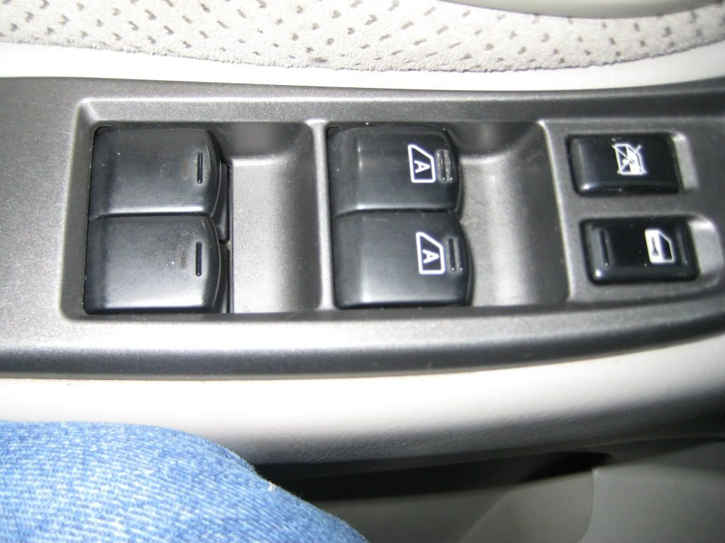
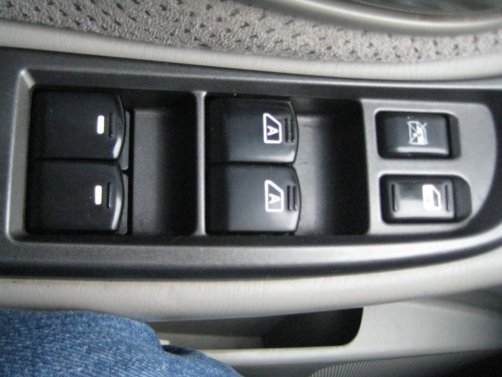
Here are the pictures of my progress on the Window Master Switch and a decription of the process involved to do this.(Tuner May Edit this Info as he see's fit)
1.Remove Switch from trim housing (3 philips head screws)
2.Seperate Switch Parts.there are 4 small locking tabs on the white piecs that hold it inside the outter shell gently slide a toothpick in next to each of these tabs to release it from the outter shell then use a small flathead screwdriver to assist in prying the white piece out.Do Not pry from the smaller 2 ends of the outter shell you will crack it.
3.Warm up your Soldering Iron and have Desolder Braid ready.Locate the (5) SMD led's small white squares this is what you are going to be removing.Briefly heat one solder pad up then apply Desolder braid and reheat you will see the solder flow into the braid remove and do next side same way.Now take a small Jewelers flathead ir a pick and plase it under one side of the SMD led and reheat while gently lifting each side to remove it from the solder pads.
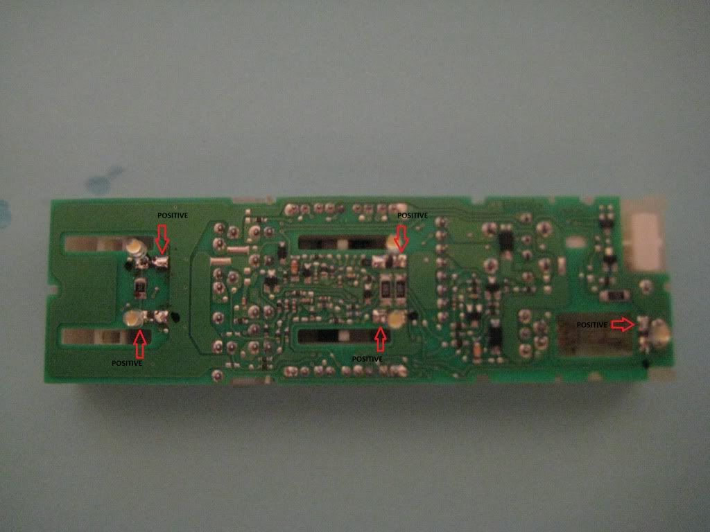
4.Prepair your new LED's for replacement.there is a restriction at how high the replacements can be off the board the maximum size i found without problems is 3/4" from the board.at the hight you deside to make your LED's bend the leads in a L shape(90*) and mark the longer lead with a marker just below the LED head this is your Positive Side(+)Example Provided then trim off the excess so it fits on the solder pad of the board only with no overlapping.
5.Prepair the Board pads to recieve your new LED's.first heat the pad up and deposite a small amount of solder to it I used Solder Size (.015 Dia) do both sides at this point next you will place and hold the LED on the Pads in a slight outward angle using the Picture Provided as correct Lead placement now heat each Lead/Pad up by placing the tip of the soldering iron on the LED Lead and watching for the Solder to flow and create the bond.
6.Reassemble inner and outter part of switch if at any time you feel resistance while sliding them back together STOP and slightly bend you LED's outward to make clearance also make sure you Do Not feel and resistance during switch operation.
BEFORE
LEAD LOCATIONS
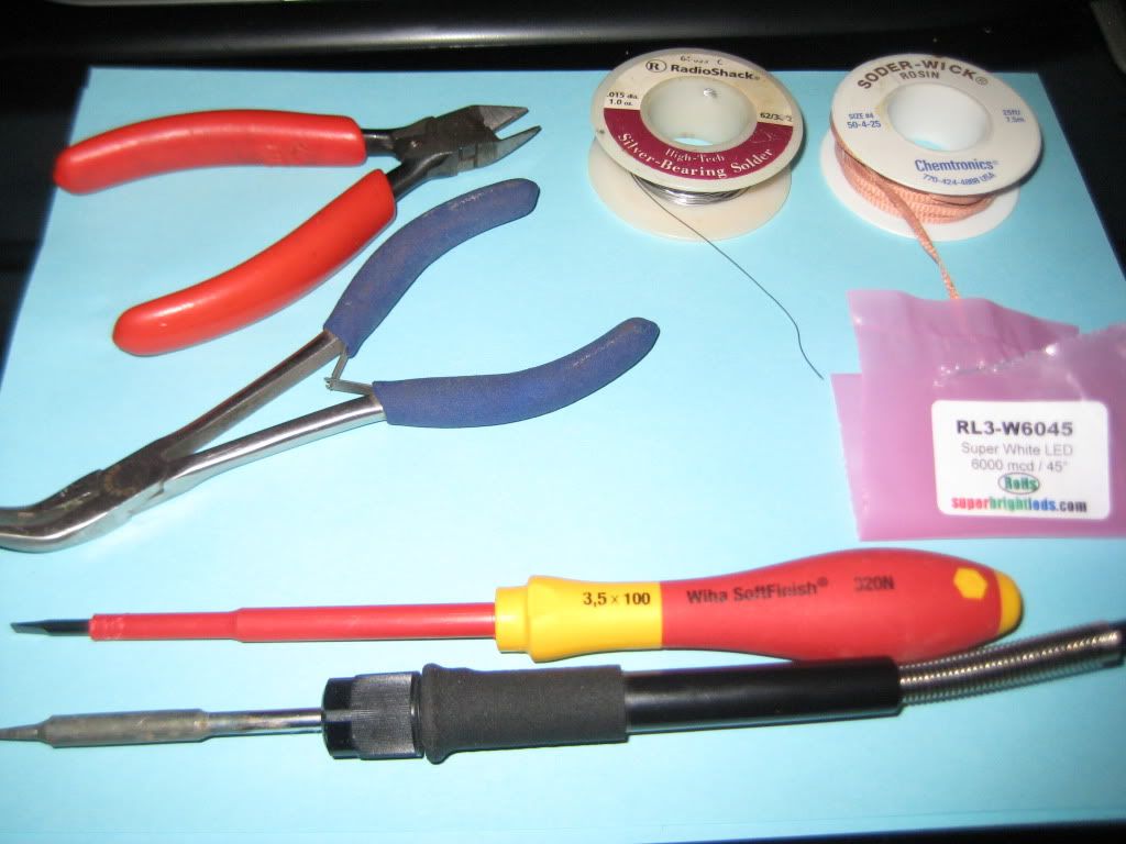
TOOLS
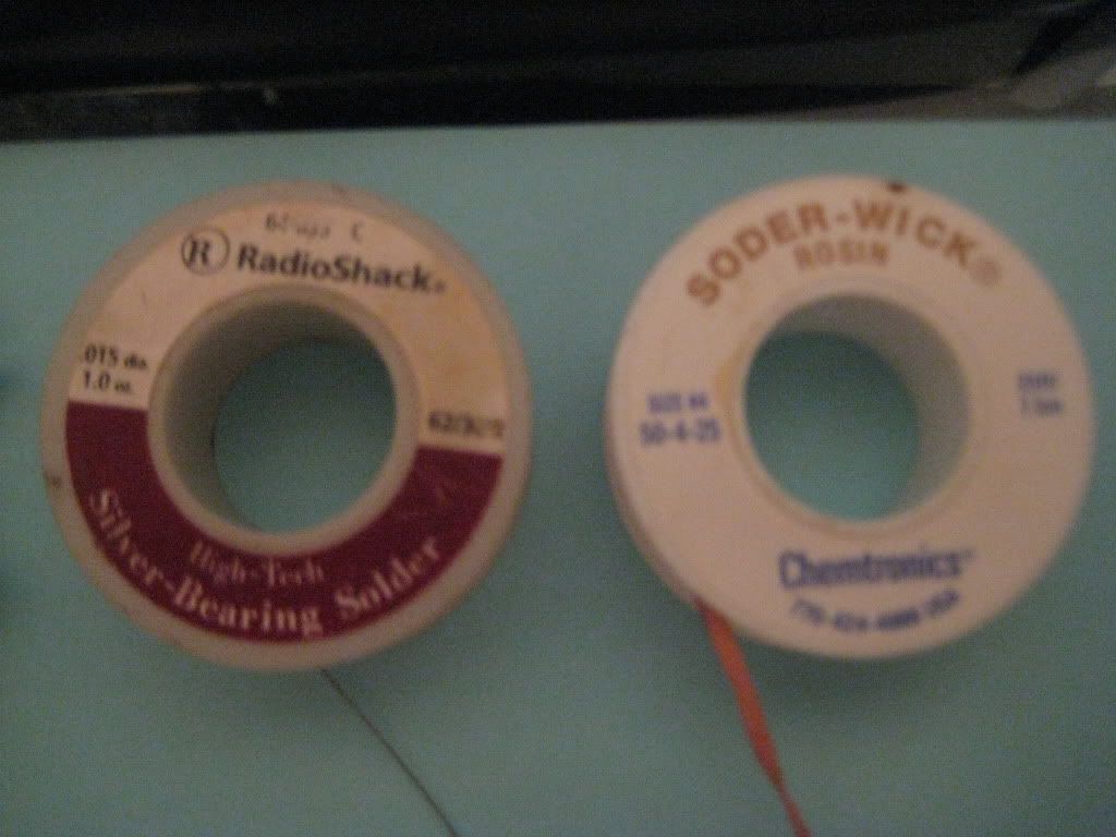
PARTS
FINISHED
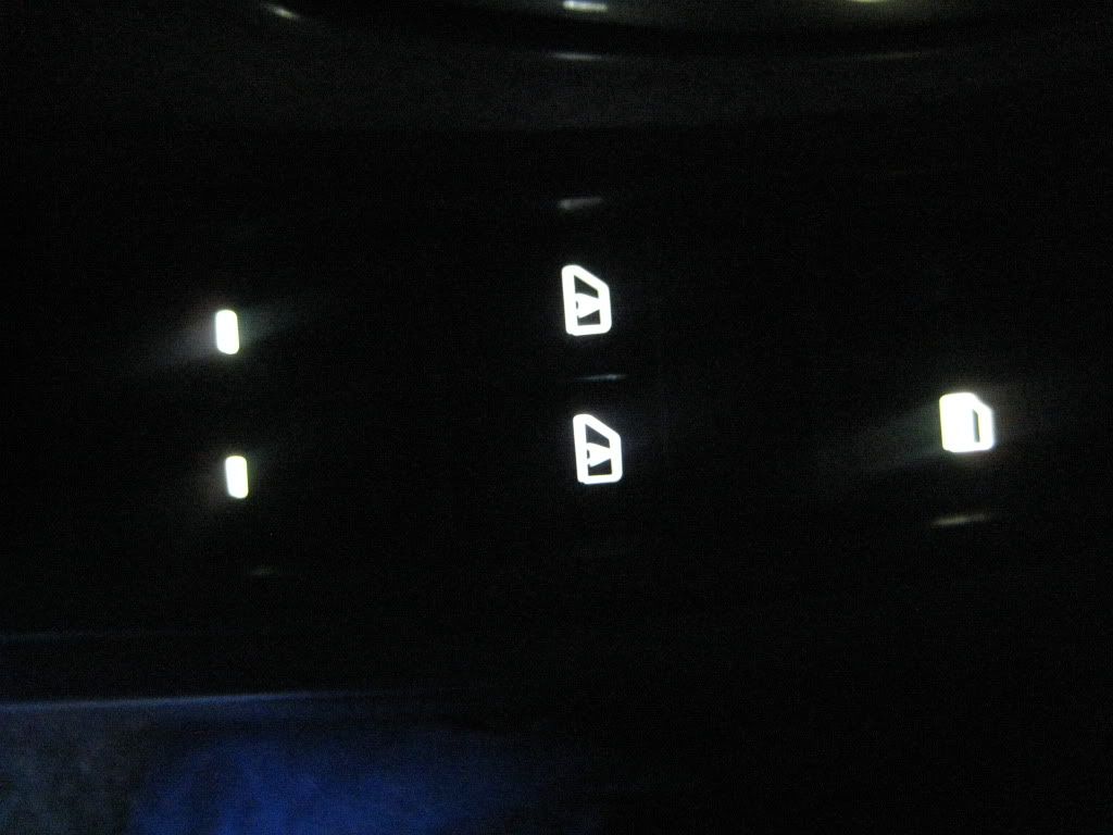
NightTime
1.Remove Switch from trim housing (3 philips head screws)
2.Seperate Switch Parts.there are 4 small locking tabs on the white piecs that hold it inside the outter shell gently slide a toothpick in next to each of these tabs to release it from the outter shell then use a small flathead screwdriver to assist in prying the white piece out.Do Not pry from the smaller 2 ends of the outter shell you will crack it.
3.Warm up your Soldering Iron and have Desolder Braid ready.Locate the (5) SMD led's small white squares this is what you are going to be removing.Briefly heat one solder pad up then apply Desolder braid and reheat you will see the solder flow into the braid remove and do next side same way.Now take a small Jewelers flathead ir a pick and plase it under one side of the SMD led and reheat while gently lifting each side to remove it from the solder pads.
4.Prepair your new LED's for replacement.there is a restriction at how high the replacements can be off the board the maximum size i found without problems is 3/4" from the board.at the hight you deside to make your LED's bend the leads in a L shape(90*) and mark the longer lead with a marker just below the LED head this is your Positive Side(+)Example Provided then trim off the excess so it fits on the solder pad of the board only with no overlapping.
5.Prepair the Board pads to recieve your new LED's.first heat the pad up and deposite a small amount of solder to it I used Solder Size (.015 Dia) do both sides at this point next you will place and hold the LED on the Pads in a slight outward angle using the Picture Provided as correct Lead placement now heat each Lead/Pad up by placing the tip of the soldering iron on the LED Lead and watching for the Solder to flow and create the bond.
6.Reassemble inner and outter part of switch if at any time you feel resistance while sliding them back together STOP and slightly bend you LED's outward to make clearance also make sure you Do Not feel and resistance during switch operation.
BEFORE
LEAD LOCATIONS
TOOLS
PARTS
FINISHED
NightTime
Last edited by cjandura; 01-26-2012 at 03:09 PM.
01-26-2012, 10:25 AM
#32
Senior Member
Thread Starter
iTrader: (4)
Join Date: Jul 2006
Location: Ontario, Canada
Posts: 5,548
Nice work thanks very much dude! All this is going to make this thread actually come to life. I've been so swamped it's been hard to think about getting started so i'ts good to see someone really pitching in!!!
I've been waiting on a few responses from customers too beffore posting there stuff
P.S. i've never used this solder wick stuff, how does it work? I've only used the solder sucker (which I've had great luck with)
I've been waiting on a few responses from customers too beffore posting there stuff
P.S. i've never used this solder wick stuff, how does it work? I've only used the solder sucker (which I've had great luck with)
01-26-2012, 10:38 AM
#33
Nice work thanks very much dude! All this is going to make this thread actually come to life. I've been so swamped it's been hard to think about getting started so i'ts good to see someone really pitching in!!!
I've been waiting on a few responses from customers too beffore posting there stuff
P.S. i've never used this solder wick stuff, how does it work? I've only used the solder sucker (which I've had great luck with)
I've been waiting on a few responses from customers too beffore posting there stuff
P.S. i've never used this solder wick stuff, how does it work? I've only used the solder sucker (which I've had great luck with)
01-26-2012, 10:39 AM
#34
Looks good. I have heard that there is a different process for the different master switches. Notice yours has the "A" on the front window switches and my 02 does not. I also notices you have the equal sized lock and lockout bottons. Someone confirm if the different switches require special methods.
01-26-2012, 10:43 AM
#35
Looks good. I have heard that there is a different process for the different master switches. Notice yours has the "A" on the front window switches and my 02 does not. I also notices you have the equal sized lock and lockout bottons. Someone confirm if the different switches require special methods.
01-26-2012, 10:45 AM
#36
Senior Member
Thread Starter
iTrader: (4)
Join Date: Jul 2006
Location: Ontario, Canada
Posts: 5,548
Looks good. I have heard that there is a different process for the different master switches. Notice yours has the "A" on the front window switches and my 02 does not. I also notices you have the equal sized lock and lockout bottons. Someone confirm if the different switches require special methods.
What's your production date? Do you have the small button for window lock?
I bet they changed the AUTO print to "A" the same time they changed that button!
01-26-2012, 03:35 PM
#37
Door Switch:
1. Remove switch assembly from trim piece and use 2 small flathead screwdrivers to GENTLY open up retainers to remove switch internals(First 2 Pics)
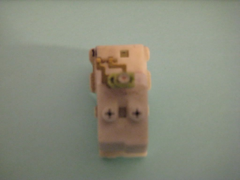
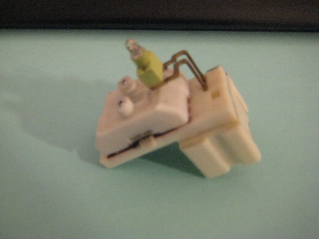
2.Mark rubber piece(greenish)and side of switch to remember direction it is going back on.remove Oe led assembly from switch unit DO NOT PLAY WITH THE WHITE MOVING PART!(Pic #3)
3.PITA part if you look at the bottom of the led holder you will see the wires are routed back up inside those 2 slots gently with small needle noise pliers pull the wires out straight and remove the led from the holder (Pic #4)
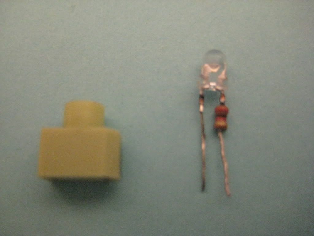
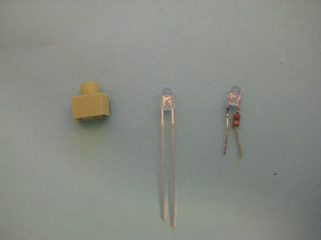
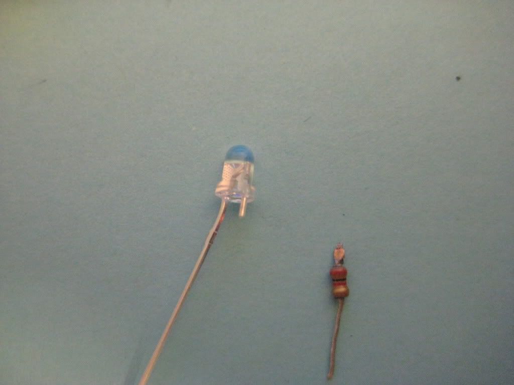
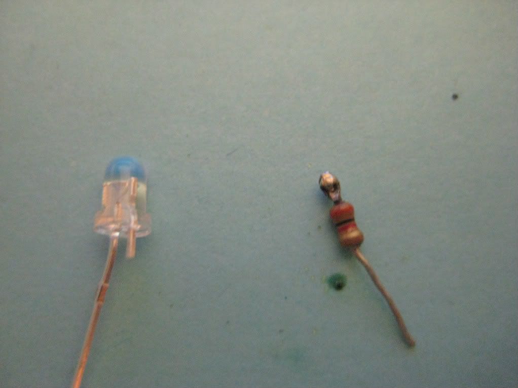
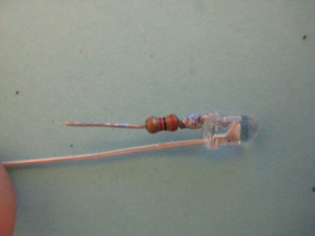
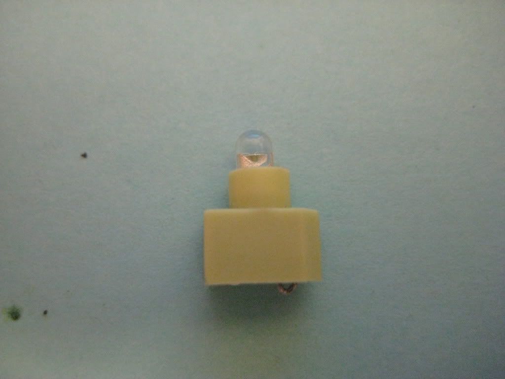
4.Surprise theres a resistor on the oe led cut it off of the oe led make sure you cut it off flush with the led dome not the resistor.Now take your new led and trim the longer(+) lead down to 1/4" and flatten it with your needle nose and flatten the short side of the resistor wire the same.now you are going to place a small ball of solder on either the new led short side or the resister short side your choice now you have to solder the 2 together while heating the solder ball and holding the pieces together should look like pic 8 when completed(Pics 5,6,7,8)
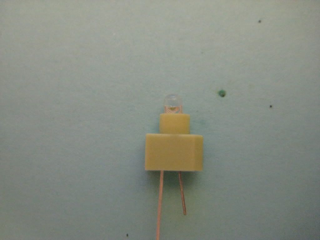
5.Reinsert new led into greenish holder it will only fit one way with the resistor and carefully trim the sticking out ends and route them up into the slots.put lamp holder assy back into switch assy and reassemble switch.now test it out.

1. Remove switch assembly from trim piece and use 2 small flathead screwdrivers to GENTLY open up retainers to remove switch internals(First 2 Pics)
2.Mark rubber piece(greenish)and side of switch to remember direction it is going back on.remove Oe led assembly from switch unit DO NOT PLAY WITH THE WHITE MOVING PART!(Pic #3)
3.PITA part if you look at the bottom of the led holder you will see the wires are routed back up inside those 2 slots gently with small needle noise pliers pull the wires out straight and remove the led from the holder (Pic #4)
4.Surprise theres a resistor on the oe led cut it off of the oe led make sure you cut it off flush with the led dome not the resistor.Now take your new led and trim the longer(+) lead down to 1/4" and flatten it with your needle nose and flatten the short side of the resistor wire the same.now you are going to place a small ball of solder on either the new led short side or the resister short side your choice now you have to solder the 2 together while heating the solder ball and holding the pieces together should look like pic 8 when completed(Pics 5,6,7,8)
5.Reinsert new led into greenish holder it will only fit one way with the resistor and carefully trim the sticking out ends and route them up into the slots.put lamp holder assy back into switch assy and reassemble switch.now test it out.
01-26-2012, 03:50 PM
#38
Senior Member
Thread Starter
iTrader: (4)
Join Date: Jul 2006
Location: Ontario, Canada
Posts: 5,548
I've done that a few times. Glad you posted it actually I would've forgot to mention this. You have to be careful not to overheat the LED electrode when soldering the resistor on.
The best way to avoid this is to 'tin' the resistor and the prong before putting them together. Then when you do put them together you only need to heat them for a quick second.
Nice work dude! Oh another tip, keep that soldering gun tip clean! I can see the old bubbled solder on there still, that's no good for a connection. Use a damp cloth to wipe the soldering tip after each application/use. That will also make the solder flow much better, and help with the overall soldering process.
(for those of you who have no idea what I'm talking about with the overheating, if you look close at the small electrode(positive) inside the LED housing, it's actually mis-alligned/twisted because it overheated and melted the housing, causing it to move. This LED was probably no good after doing this, they very rarely light after they shift, but nevertheless it's something to watch for. If it moves even a bit in the housing, discard it, it'll only stop working down the road and you'll have to take it all apart again
Last edited by TunerMaxima3000; 01-26-2012 at 03:53 PM.
01-26-2012, 05:06 PM
#39
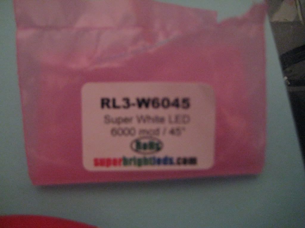
Ok what led swap should be next? i'm currently waiting on some more supplies i found them a bit cheaper .18 cent ea. for 3mm and 5mm and .30 cent for some pink ones that im going to use in my niece's car.