
02-03 Bose 6CD changer Audio cutout fix!! "RePosted"


Thread Starter
Senior Member
iTrader: (13)
Joined: Nov 2007
Posts: 1,364
From: Burlington, Ontario Canada
02-03 Bose 6CD changer Audio cutout fix!! "RePosted"
Hope this helps those looking to fix the audio cutout on thier Bose Head Units, I have found a number of threads on this topic but most of the links seem to be dead ... so I have reassembled my copy of the write up.
Bose write up on audi cut out:
Bose 6 pack CD AUDIO cut out repair by: Chris.s@TMEC
Removal of the stereo from the dash…
Tools required:
Large flat head screwdriver with a thick terry or 100% cotton cloth
Phillips screwdriver
Soldering iron with solder and wick (used to remove solder)
Set of needle nose pliers.
1. IMPORTANT!! Remove ANY TAPES AND ALL CDS from the changer!!!
2. Disconnect battery negative terminal
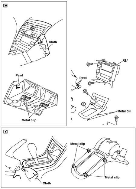
3. Remove the vent sash using the flat screwdriver with the cloth over top (if
done carefully you should not damage your dash so don’t worry)
4. Pop out the shifter trim, put shifter in 4th (manual) or L(auto) to make
removal easier.
5. Once you remove the 4 screws from the HU bracket pull the unit outwards
and prop it up on either the shifter or dash so you can remove the harnesses.
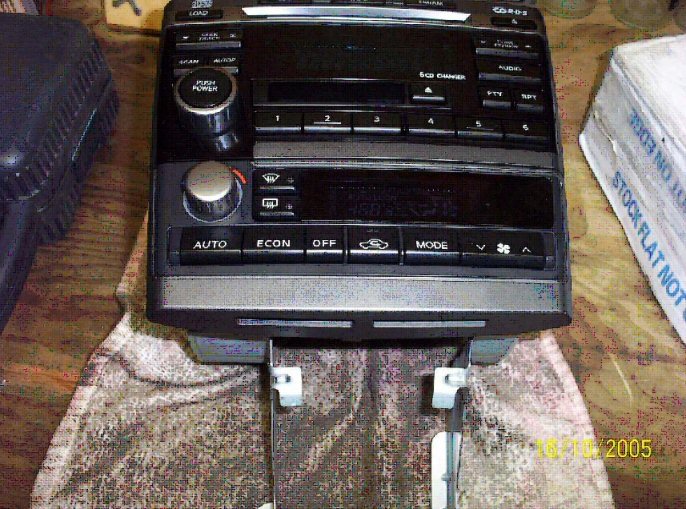
Stereo and climate control units removed from vehicle
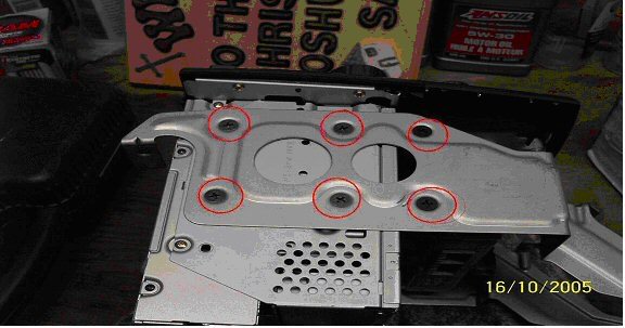
Remove these screws. (you may need to use a ratchet)
Remove…
Use a flat screwdriver for these clips to remove the face.
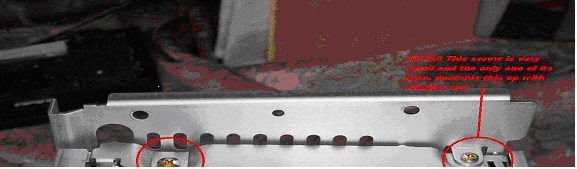
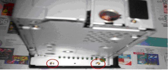
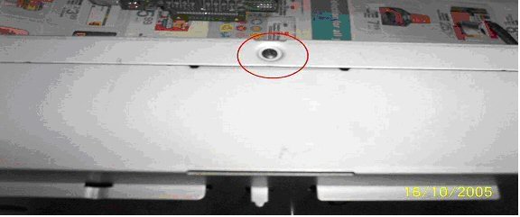
Remove these. The top right one is a really small screw.
Bose write up on audi cut out:
Bose 6 pack CD AUDIO cut out repair by: Chris.s@TMEC
Removal of the stereo from the dash…
Tools required:
Large flat head screwdriver with a thick terry or 100% cotton cloth
Phillips screwdriver
Soldering iron with solder and wick (used to remove solder)
Set of needle nose pliers.
1. IMPORTANT!! Remove ANY TAPES AND ALL CDS from the changer!!!
2. Disconnect battery negative terminal
3. Remove the vent sash using the flat screwdriver with the cloth over top (if
done carefully you should not damage your dash so don’t worry)
4. Pop out the shifter trim, put shifter in 4th (manual) or L(auto) to make
removal easier.
5. Once you remove the 4 screws from the HU bracket pull the unit outwards
and prop it up on either the shifter or dash so you can remove the harnesses.
Stereo and climate control units removed from vehicle
Remove these screws. (you may need to use a ratchet)
Remove…
Use a flat screwdriver for these clips to remove the face.
Remove these. The top right one is a really small screw.
Last edited by Ghost_54; Feb 25, 2014 at 06:44 PM.
Thread Starter
Senior Member
iTrader: (13)
Joined: Nov 2007
Posts: 1,364
From: Burlington, Ontario Canada
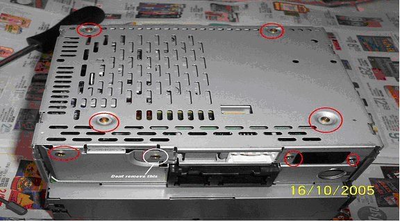
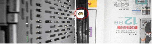
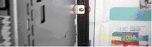
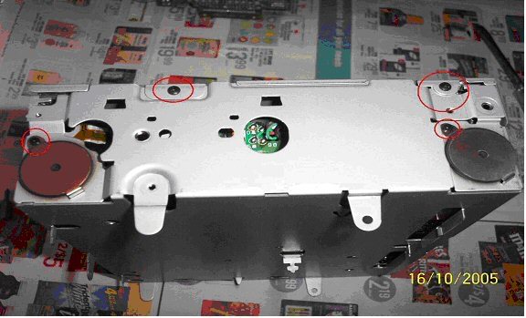
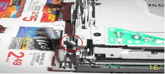
Remove these. Don’t remove the one circled in white
Use a screw driver to pop the plate off.
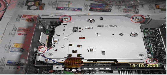
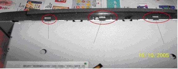
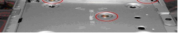
Once inside, remove the tape deck by removing the 4 circled
screws and pulling up on the tape unit.
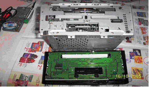
With tape deck removed….
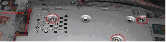
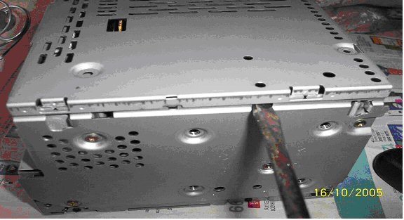
Remove the screws holding the 2 side plates on. Remove
these plates by sliding them upwards.
(opposite side not shown)

With pliers, twist this so it is inline with the slot on the PCB

Remove this ribbon cable by pulling it out.
You should now be able to pull the “Radio/tape” portion of the
unit up and completely clear of the CD changer.
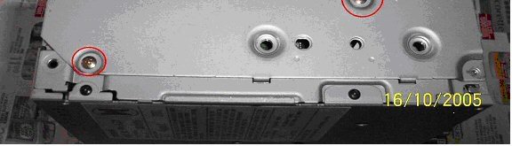
Begin removing the screws from the CD changer cover….
Thread Starter
Senior Member
iTrader: (13)
Joined: Nov 2007
Posts: 1,364
From: Burlington, Ontario Canada

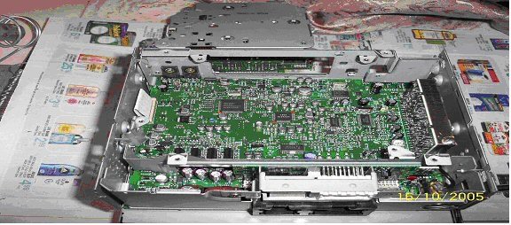
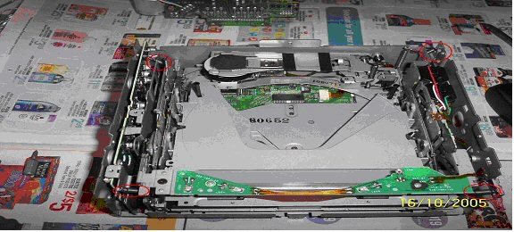
CD Changer with cover off…
Note:
The 2 plastic posts on either side of the laser “May” fall out during
handling. Simply put them back before reassembly.
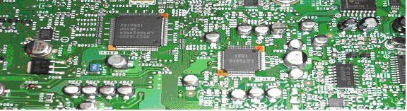
Remove these black screws to expose the daughter board.
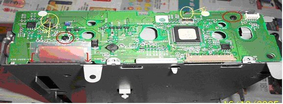
1. Remove the 2 black screws from the board.
2. Desolder the 2 posts circled in yellow. Remove as much
solder as possible using solder wick.
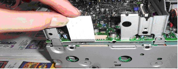
3. Unlatch the brown ribbon connector by CAREFULLY sliding
the 2 leavers on either end away from the connector. This
ribbon cable should slide out of the connector with close to 0
resistance.
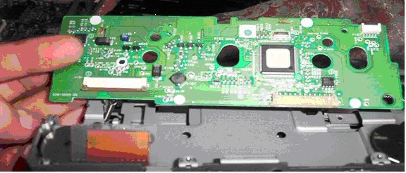
3. Bend the posts which were de-soldered so that you can lift
this PCB out.
Last edited by Ghost_54; Feb 25, 2014 at 02:59 PM.
Thread Starter
Senior Member
iTrader: (13)
Joined: Nov 2007
Posts: 1,364
From: Burlington, Ontario Canada
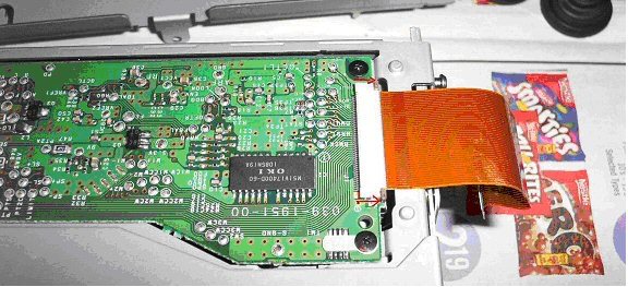
***This ribbon connector is one of 2 responsible for the audio cut out.***
Put this aside.
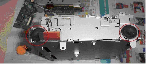
Remove the 2 screws and the steel plate covering the rubber
mounts. (do this on both sides)
Remove these 4 springs carefully with a set of small needle
nose pliers.
Remove the 4 rubber mounts from each corner. Be careful not
to puncture these as they are liquid filled.
Remove the CD Changer from the chassis…
Remove this ribbon cable from the bottom of the CD changer
HERE IS THE PROBLEM!!!!
These types of semi-rigid cables are notorious for wearing and not making
a complete connection in the connector type used. The contacts bend over
time with the pressure from the contact pins. Since the ribbon is no longer
in its original flat shape, a poor contact is made and therefore NO *******
AUDIO
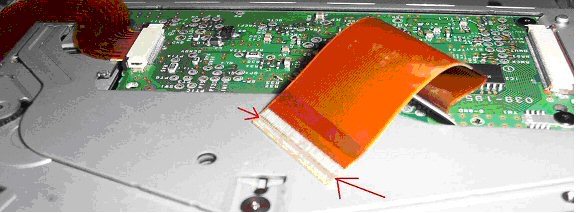
My “solution” is simple. Reseat the ribbon cable back into the connector
but do not insert it fully. This way the pins are going to press on a “fresh”
part of the ribbon.
Sadly I do not believe this is a permanent solution. However It has worked
for myself and another. I would expect this to last at least as long as the
Original connection did.
A permanent and proper solution would be to solder brand new wires from
one PCB to the other. This isn’t exactly easy. If I do experience another
Failure before I choose to replace the HU for something else then I will try
it.
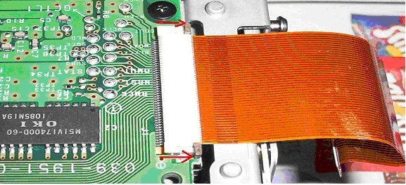

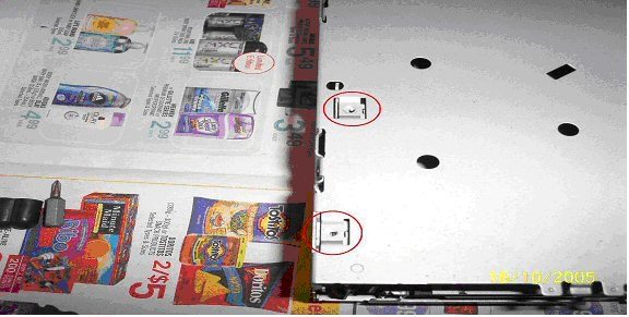
Here are pictures of how much to leave the connector out. They are not the
best pictures but should be good enough. Do this for both sides of the
ribbon cable.
Reassemble in the reverse order. (don’t you hate that…)
When putting the rubber liquid filled mounts back in, make sure that each
of the posts from the CD player assembly is completely inside the rubber
hole.
Put this aside.
Remove the 2 screws and the steel plate covering the rubber
mounts. (do this on both sides)
Remove these 4 springs carefully with a set of small needle
nose pliers.
Remove the 4 rubber mounts from each corner. Be careful not
to puncture these as they are liquid filled.
Remove the CD Changer from the chassis…
Remove this ribbon cable from the bottom of the CD changer
HERE IS THE PROBLEM!!!!
These types of semi-rigid cables are notorious for wearing and not making
a complete connection in the connector type used. The contacts bend over
time with the pressure from the contact pins. Since the ribbon is no longer
in its original flat shape, a poor contact is made and therefore NO *******
AUDIO
My “solution” is simple. Reseat the ribbon cable back into the connector
but do not insert it fully. This way the pins are going to press on a “fresh”
part of the ribbon.
Sadly I do not believe this is a permanent solution. However It has worked
for myself and another. I would expect this to last at least as long as the
Original connection did.
A permanent and proper solution would be to solder brand new wires from
one PCB to the other. This isn’t exactly easy. If I do experience another
Failure before I choose to replace the HU for something else then I will try
it.
Here are pictures of how much to leave the connector out. They are not the
best pictures but should be good enough. Do this for both sides of the
ribbon cable.
Reassemble in the reverse order. (don’t you hate that…)
When putting the rubber liquid filled mounts back in, make sure that each
of the posts from the CD player assembly is completely inside the rubber
hole.
Last edited by Ghost_54; Feb 25, 2014 at 03:00 PM.
Thread Starter
Senior Member
iTrader: (13)
Joined: Nov 2007
Posts: 1,364
From: Burlington, Ontario Canada
Sorry for breaking up the write up but one can only post 15 pic's at one time ... I found this write up to be done exceptionally well done
Perhaps one of the Mod's may move this to the sticky section
Perhaps one of the Mod's may move this to the sticky section
Last edited by Ghost_54; Feb 25, 2014 at 03:30 PM.


very nice ghost, thanks. and by the way there is a technique or method were you do not need to solder/unsolder at all.
i did it that way and it was much easier.
I will look for the post/info where I got that method/step with out soldering. But IIRC it was just the final step around the daughter board in using "reverse" engineering kind of approach to that step in the dismantling.
I am thinking about doing this again, even though I have the unknown CD ERR F3 not to be confused with CD ERR F0. I kinda have evolved to not use CDs at all past 2 years sucks, but I deal.
i did it that way and it was much easier.
I will look for the post/info where I got that method/step with out soldering. But IIRC it was just the final step around the daughter board in using "reverse" engineering kind of approach to that step in the dismantling.
I am thinking about doing this again, even though I have the unknown CD ERR F3 not to be confused with CD ERR F0. I kinda have evolved to not use CDs at all past 2 years
sucks, but I deal.
Thanks good to know I will look at that. I might have to pm you for more detail on the braket, and by the way mine is CD ERR F3, and no one here or outside the org can tell me what it is.

Thread
Thread Starter
Forum
Replies
Last Post
hez8813
5th Generation Maxima (2000-2003)
11
Mar 12, 2020 12:06 AM
popdedop
7th Generation Maxima (2009-2015)
6
Sep 11, 2015 11:17 AM