
For those with switch-backs


For those with switch-backs
I just purchased the 6ohm resistors for my front turn-signal switchbacks and am not sure what wires to splice...anyone that has done this know, or does anyone have any idea which of the 3 wires is ground, turn signal and running light??? And pictures if at all possible! This is an easy task, but I am making it harder than it should be. 
dan
dan

you should get a Volt meter, you can even get one with a light bulb in it for lik eless then $10 @ Walmart or Autozone. they always come in handy when doing mods. I had done this mod with my Avalanche. Make sure you mount tha resistor to metal, another member who installed these burned a hole in his Light housing.

Originally Posted by !PrjctMax!
you mean do NOT put it on metal?*** lol
No, I mean mount it to metal/sheet metal. Do not mount to plastic or just leave it lying around taped up, cause you willl have problems.
This is how I install mine..
this is the proper way to install them, I had no issues what so ever.
Read the warning:

alright sounds good. with the blue little connectors....do you have to peel the rubber off of the wires or do you just put the equalizer wire in one end and then the ground/turn wire in the other with NO PEELING of the rubber? and then you just snap it shut? sry these blue things are kind of confusing me
thanks for the help
dan
thanks for the help
dan
sweet! so this seems easier than I thought! so when you snap it shut does that little metal thing break through the rubber or something and then it makes it work? as for mounting the equalizers, i'd assume that you can't use double-sided tape since it would melt right through that as well?
correct, def no 3m tape, screws a must.
I hope you have room to mount them, you can always relocate them & run wires, make sure you use thick wires thought, probably 12 gauge would be good.
I hope you have room to mount them, you can always relocate them & run wires, make sure you use thick wires thought, probably 12 gauge would be good.


If anyone wants to do this mod... I have all the parts to do this...
I can ship them to you $40 this includes bulbs & resistors...
Good stuff!
let me know...
blulytes@comcast.net
I can ship them to you $40 this includes bulbs & resistors...
Good stuff!
let me know...
blulytes@comcast.net
Originally Posted by Blulytes
If anyone wants to do this mod... I have all the parts to do this...
I can ship them to you $40 this includes bulbs & resistors...
Good stuff!
let me know...
blulytes@comcast.net
I can ship them to you $40 this includes bulbs & resistors...
Good stuff!
let me know...
blulytes@comcast.net
 $25 per bulb and about $15 for both resistors=about $70 shipped, you are saving about $30!!


Originally Posted by jsmithsole
Check my sticky, the wires may be the same color. Just get a tester and you'll be fine...
 The 3 wires are solid blue (which im certain is ground) and then there is red/black and green/orangeish.
 From the research that I have been doing I am almost positive that the turn signal wire is green/orange, but not 100%. I've gotten a skematic and a troubleshooting diagram and no where did they mention a red/black wire!
Anyways, there is almost NO PLACE to mount the resistor within the wires reach(need to mount on metal, NOT plastic), so for now I am just going to accept the fast blinking and one weekend I will do the resistors with my daddy!
thanks for everyones' input!
dan

Only person that I know of for now is Jsmith...and he mounted his in the rear lights somewhere...where I do not know, but he only has resistors in the rear...wanna chime in jsmith?
Originally Posted by Blulytes
If anyone wants to do this mod... I have all the parts to do this...
I can ship them to you $40 this includes bulbs & resistors...
Good stuff!
let me know...
blulytes@comcast.net
I can ship them to you $40 this includes bulbs & resistors...
Good stuff!
let me know...
blulytes@comcast.net
For all those interested in what wires you place the resistor on..
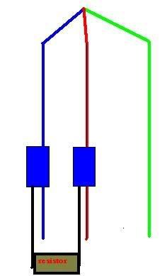
The Red wire to the Blue Wire... Easy.
As for why I am selling...
I might be upgrading to an 07... so I returned to stock...
I don't need them.. so my loss is your gain.
The Red wire to the Blue Wire... Easy.
As for why I am selling...
I might be upgrading to an 07... so I returned to stock...
I don't need them.. so my loss is your gain.
Just take a multimeter or similar device. clamp it onto the wire with pinching crocodile clamps, put on the blinker and see if you get a response. Turn the blinker off and the voltage goes back to 0.
connect blue with red, check if nothing when the blinker is on connect blue and green and check again.
I just saw a max on the highway with the FAST blinker in the front and it looked well...........HORRIBLE!
connect blue with red, check if nothing when the blinker is on connect blue and green and check again.
I just saw a max on the highway with the FAST blinker in the front and it looked well...........HORRIBLE!
Originally Posted by xoomer.com
Just take a multimeter or similar device. clamp it onto the wire with pinching crocodile clamps, put on the blinker and see if you get a response. Turn the blinker off and the voltage goes back to 0.
connect blue with red, check if nothing when the blinker is on connect blue and green and check again.
I just saw a max on the highway with the FAST blinker in the front and it looked well...........HORRIBLE!
connect blue with red, check if nothing when the blinker is on connect blue and green and check again.
I just saw a max on the highway with the FAST blinker in the front and it looked well...........HORRIBLE!

I might do the resistors in the future, but for now I am happy with the LED's
Originally Posted by Blulytes
The Red wire to the Blue Wire... Easy.
Originally Posted by !PrjctMax!
yea, I could do all that and also extend the wires since there is no metal to mount them on nearby. And it obviously made you look twice with the fast blinking, so that is a good thing! People will notice you better while making quick moves and dashes
I might do the resistors in the future, but for now I am happy with the LED's
I might do the resistors in the future, but for now I am happy with the LED's
Originally Posted by !PrjctMax!
not really...you need to connect one side of the resistor with the blue clip to the ground, which I believe is the blue wire, and the other side connects to either the black/red or orange/orangish
I did it, it works... no problems...
If you really want to back up your work.... do the multi meter....
this is how I found the wires anyway.
Originally Posted by Blulytes
Whatever dude...
I did it, it works... no problems...
If you really want to back up your work.... do the multi meter....
this is how I found the wires anyway.
I did it, it works... no problems...
If you really want to back up your work.... do the multi meter....
this is how I found the wires anyway.
OK...
not sure by what you mean another wire...
this is a crude drawing of how it works...
no cutting just clips...
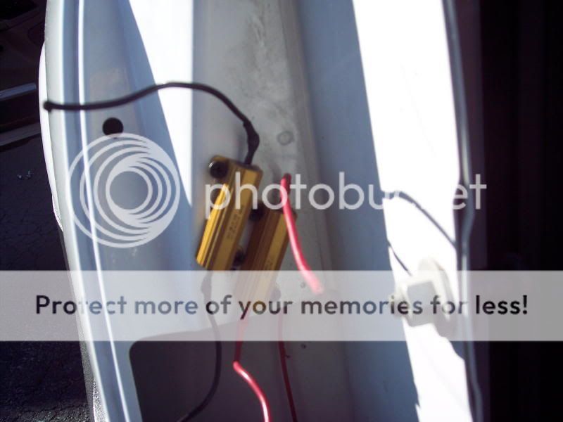
As to where I installed them, using zip ties, I was able to mount it right behind the light hanging from the frame... this way it was not contacting the body...
not sure by what you mean another wire...
this is a crude drawing of how it works...
no cutting just clips...
As to where I installed them, using zip ties, I was able to mount it right behind the light hanging from the frame... this way it was not contacting the body...
Originally Posted by Blulytes
OK...
not sure by what you mean another wire...
this is a crude drawing of how it works...
no cutting just clips...
As to where I installed them, using zip ties, I was able to mount it right behind the light hanging from the frame... this way it was not contacting the body...
not sure by what you mean another wire...
this is a crude drawing of how it works...
no cutting just clips...
As to where I installed them, using zip ties, I was able to mount it right behind the light hanging from the frame... this way it was not contacting the body...

thanks for al the good info!

dan
Originally Posted by Blulytes
I did the ties to the wires, so that the resistor was not contacting any surface... worked fine... even had my car on the side of the road with hazards on for 2 hours... no problems!
Originally Posted by Blulytes
I did the ties to the wires, so that the resistor was not contacting any surface... worked fine... even had my car on the side of the road with hazards on for 2 hours... no problems!
Originally Posted by Blulytes
If anyone wants to do this mod... I have all the parts to do this...
I can ship them to you $40 this includes bulbs & resistors...
Good stuff!
let me know...
blulytes@comcast.net
I can ship them to you $40 this includes bulbs & resistors...
Good stuff!
let me know...
blulytes@comcast.net

Thread
Thread Starter
Forum
Replies
Last Post
Ghozt
7th Generation Maxima (2009-2015)
46
Oct 19, 2012 01:25 AM
!PrjctMax!
6th Generation Maxima (2004-2008)
7
May 15, 2007 01:00 PM