

00VI Starting Problem


Ok thats awesome. I won't need an extra rear cover. I'll go that route then. Let me get the pic to show you. Ok the bottom cover is 4th gen obviously. The nipple off the right side is what I'm talking about.
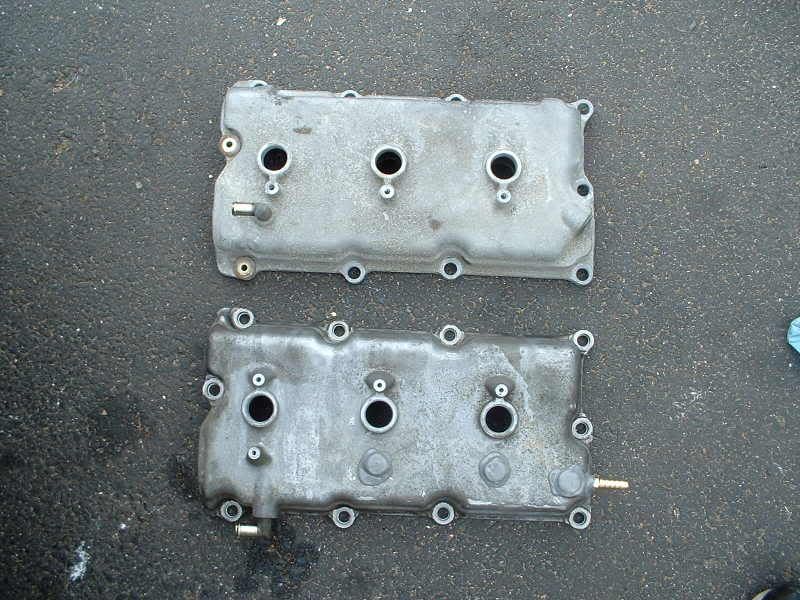
Speed racer was saying to hook the pcv to the barb fitting on the right side. I thought pcv went to the 90 degree nipple. What am I missing?
:edit: Also Maximus...what are the dimensions of the bosses cut?
Speed racer was saying to hook the pcv to the barb fitting on the right side. I thought pcv went to the 90 degree nipple. What am I missing?
:edit: Also Maximus...what are the dimensions of the bosses cut?


hey cdq2125.. from the picture and explanation you are giving.. the barb fitting (on right side) = 90 degree nipple.. the nipple on the left side of the valve cover is what connects the rear valve cover to the front valve cover.. on that pic the brass nipple thats jb welded to the valve cover is where the pcv originally goes.. but clearance is an issue with the swap.. so its easier to put a 90 there and run a inline pcv..
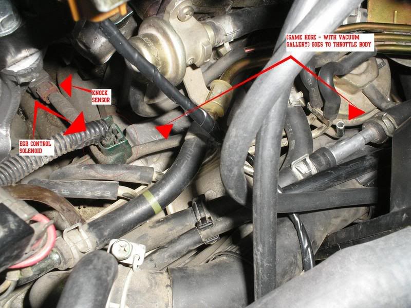
hey speed.. in this picture is the EGR control solenoid that is controlling my CEL for the EGR hi/flow code.. it is normally hooked up to a nipple underneath the 4th Gen TB.. well since i am using the 5th gen TB and it doesnt have this nipple, i dont know where to connect it at.. and since you eliminated the vacuum gallery on your swap its hard for me to see where you have this sensor hooked up at.. if you could show me i would appreciate it..
Can anyone post pics of where they hooked up to vacum sources? Cause im pulling some codes up just recently for EVAP and some pressure sensor crap...i have no idea what it is..but im starting to think its lack of vacuum from the way i attached the smalle vacuum lines FROM the gallery to the VI.
These are the codes im pulling up:
08-03 = Absolute Pressure Sensor
09-03 = EVAP Canister vent control valve
i was mostly just curious, for pics of the gallery thats above the EGR valve and right underneath that TB, from there where did you guys run the lines?
BTW, this is a VERY helpfull thread, i had to figure this stuff out all by myself and FSM basically lol...
Originally Posted by Cdg2125
Ok so barb fitting on the right side is pcv. The 90 degree nipple on the left side is what?
xerox - whats the other code (besides evap).. your vacuum issue with the evap can be fixed if you look in the FSM in the EC (engine control) section page 25.. its shows how the evap canister purge control valve hooks up to the vacuum gallery..
Originally Posted by 97Maximus
xerox - whats the other code (besides evap).. your vacuum issue with the evap can be fixed if you look in the FSM in the EC (engine control) section page 25.. its shows how the evap canister purge control valve hooks up to the vacuum gallery..
cdq2125 - i dont know exactly what size it is used.. that should work though.. also about the dimensions for cutting the bosses.. you just have to use logic.. you still want to have the same height as originally.. so when cutting the diagonal leave a little on the top and cut at an angle to achieve enough of the face to be cut off as shown in the pic..
cdq2125 - yes there is.. in the EC section.. there are enough diagrams to figure it all out..
xerox - the MAP sensor is whats causing your code.. it needs to be hooked up to the UIM..
cdq2125 - yes there is.. in the EC section.. there are enough diagrams to figure it all out..
xerox - the MAP sensor is whats causing your code.. it needs to be hooked up to the UIM..

Originally Posted by 97Maximus
hey speed.. in this picture is the EGR control solenoid that is controlling my CEL for the EGR hi/flow code.. it is normally hooked up to a nipple underneath the 4th Gen TB.. well since i am using the 5th gen TB and it doesnt have this nipple, i dont know where to connect it at.. and since you eliminated the vacuum gallery on your swap its hard for me to see where you have this sensor hooked up at.. if you could show me i would appreciate it..
Originally Posted by 97Maximus
cdq2125 - i dont know exactly what size it is used.. that should work though.. also about the dimensions for cutting the bosses.. you just have to use logic.. you still want to have the same height as originally.. so when cutting the diagonal leave a little on the top and cut at an angle to achieve enough of the face to be cut off as shown in the pic..
cdq2125 - yes there is.. in the EC section.. there are enough diagrams to figure it all out..
xerox - the MAP sensor is whats causing your code.. it needs to be hooked up to the UIM..
cdq2125 - yes there is.. in the EC section.. there are enough diagrams to figure it all out..
xerox - the MAP sensor is whats causing your code.. it needs to be hooked up to the UIM..
 ive tried all sorts of different things...
speedracer - i had mine setup like that before.. i had the egr sensor ran to the nipple next to where you connect the pcv hose.. and still got a code.. so it made me think that it needed to be closer to the TB like original.. so you have bot the the egr sensor and map sensor hooked up to the nipple next to where you connect the pcv hose and are not getting a CEL??
xerox - i will take some pics for you to show you how i have it hooked up.. youll have to give a day or so.. i have alot going on tmrw and dont know if i can get to it.. but ill get you something soon..
Originally Posted by XeroX
Can anyone post pics of where they hooked up to vacum sources? Cause im pulling some codes up just recently for EVAP and some pressure sensor crap...i have no idea what it is..but im starting to think its lack of vacuum from the way i attached the smalle vacuum lines FROM the gallery to the VI.
These are the codes im pulling up:
08-03 = Absolute Pressure Sensor
09-03 = EVAP Canister vent control valve
i was mostly just curious, for pics of the gallery thats above the EGR valve and right underneath that TB, from there where did you guys run the lines?
BTW, this is a VERY helpfull thread, i had to figure this stuff out all by myself and FSM basically lol...
These are the codes im pulling up:
08-03 = Absolute Pressure Sensor
09-03 = EVAP Canister vent control valve
i was mostly just curious, for pics of the gallery thats above the EGR valve and right underneath that TB, from there where did you guys run the lines?
BTW, this is a VERY helpfull thread, i had to figure this stuff out all by myself and FSM basically lol...
Originally Posted by 97Maximus
speedracer - i had mine setup like that before.. i had the egr sensor ran to the nipple next to where you connect the pcv hose.. and still got a code.. so it made me think that it needed to be closer to the TB like original.. so you have bot the the egr sensor and map sensor hooked up to the nipple next to where you connect the pcv hose and are not getting a CEL??
Originally Posted by speed racer
You need to route that to the manifold somehow. It need a vacuum from the intake manifold. You can connect a three way barb to a vacuum hose that's already going to the manifold to solve this or just connect it to where your fpr goes to the intake manifold. Remember my setups shows everything going to that one nipple on top of the manifold next where you connect for the pcv hose.

no i havent done that yet.. i will try that also.. see thats what i was thinking.. as long as it is hooked up to the UIM it should have the same amount of vacuum pressure at any point across the manifold..
By the way when I first did my setup I used the existing vacuum gallery yall are all using and did not connect anything to the TB since I was using the 5th gen. I had no codes and drove the car for 500 miles. The metal line sticking vertically up doesn't do anything at all if I remember correctly. You could put a rubber cap to close it up though.
All of them were 3/16" hoses. There's only one place to connect to and that's the nipple on top of the UIM next to where you connect the pcv hose. All vacuum lines that are 3/16" can connect to that one nipple.
Ok so off the 3/16 FPR nipple everything can be t'd into that. I have to drill my manifold for the nipple on the left of the PCV nipple since that was jb welded on my manifold. That nipple I need to drill is supposed to be used for the FPR I think....Maybe I'll drill for a bigger nipple so all those hoses can be vacuumed from that source. I was planning on using 5/16 tho, should I just use the 3/16?
gtr let me know if you get that to work.. i have tried hooking it up the way speed said to and still got a code.. i dont know if i have a bad sensor or not (still have to check that).. but if it works for two ppl it is probably certain i have a bad sensor.. thanks
Originally Posted by speed racer
Both those sensors need a vacuum source. Look in the FSM for the Absolute pressure sensor and evap canister purge control solenoid valve. I believe is pg. EC14 of the FSM. Now trace back those metal lines to see where the hoses connect to. The outlet of the metal lines will need a vacuum from the intake manifold.
Originally Posted by 97Maximus
xerox - i will take some pics for you to show you how i have it hooked up.. youll have to give a day or so.. i have alot going on tmrw and dont know if i can get to it.. but ill get you something soon..
If you can get me pics, they will be MUCH appreciated, no rush at all 
Seams like everyone has a different way of running the vacuum lines, i dont think i have seen the same "setup" more than once from what i have looked at on the org.

Here is what i put together to possibly help some of you out. I noticed that some of the maximas have one if the tubes on the vacuum galley empty while others are used....dunno if thats how they came stock or not. anyways, here is how mine is hooked up. If someone can get me a clear pic of the vacuum galley itself I can make a better diagram.


goldtooth - thanks for those pics.. thats how i have everything hooked up.. if you look in post #52 you will see a pic i posted.. in that pic you will see a metal vacuum line with an arrow pointing to it with no hose on it.. where do you have that routed to?? thats the only other question i have.. thanks -Jason
i dont think i have that metal vacuum line.....and please tell me if u have any vacuum lines going to under the throttle body, because i do not....there is just a covered nipple under mine, and i never touched it, thats how it was since stock. it s all probably cuz mine is a 99
This may be a PITA ? but what do you guys think about the vacuum gallery? Do you think I should just eliminate it? Seems like you guys have more problems keeping the gallery and not as much with t'd hoses. Plus, what was the hose that usually goes under the tb? I have a custom nipple that krismax put on my block for that hose...thanks
hmm very good pics!
Wut about the boost sensor tho? i saw that on the dek motor i pulled the VI off of, but we dont have that on the 4th gens do we? also what the hell is that? haha
Wut about the boost sensor tho? i saw that on the dek motor i pulled the VI off of, but we dont have that on the 4th gens do we? also what the hell is that? haha
Originally Posted by XeroX
hmm very good pics!
Wut about the boost sensor tho? i saw that on the dek motor i pulled the VI off of, but we dont have that on the 4th gens do we? also what the hell is that? haha
Wut about the boost sensor tho? i saw that on the dek motor i pulled the VI off of, but we dont have that on the 4th gens do we? also what the hell is that? haha

I located the unsupplied hose running from the EGR solenoid and plugged it to vacuum on monday. I didnt reset the ECU afterward I noticed today that my CEL just went out.. The bulb is still working, ( streetz) and I started the car several times after discovering the resolved CEL and it hasnt yet come back.
streetz) and I started the car several times after discovering the resolved CEL and it hasnt yet come back.