

Making connector for EU - Help!


Thread Starter

Joined: Jul 2002
Posts: 2,063
From: Reno, NV
Making connector for EU - Help!
Ok I am trying to install my EU. So to start I wanted to make a connector for ease of installation. It will end up being a plug and play application.
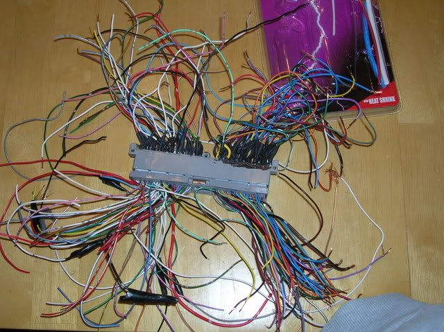
So I started out by buying a used ECU and removing the main harness pin connection. Which gave me this:

I also got a main harness connector with all the wires and all that. And that was this:

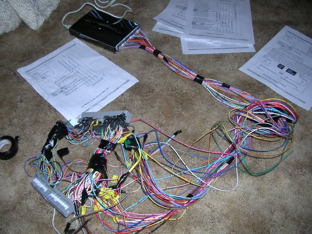
I soldered all the wires to the pins. And this is the end result.

I was very proud of myself, I went and plugged the harness into the car to make sure everything was working. I start the car and here comes the cell, so I check it out and come to find out, for whatever reason the harness I have doesn't have all the necessary wires. It's missing like 13 wires. So I figure ok I think I can deal with this.
But now here's my delimma, how do I install the extra wires into the main harness connector? (shown here)

Is it possible to install more wires in, or am I screwed and have to buy another connector?
If anyone have any suggestions I'd appreciate it. I'm hoping I don't have to try and buy a new main harness connector. Which means I'll be waiting for someone to get into an accident and part out their car.
So I started out by buying a used ECU and removing the main harness pin connection. Which gave me this:
I also got a main harness connector with all the wires and all that. And that was this:
I soldered all the wires to the pins. And this is the end result.
I was very proud of myself, I went and plugged the harness into the car to make sure everything was working. I start the car and here comes the cell, so I check it out and come to find out, for whatever reason the harness I have doesn't have all the necessary wires. It's missing like 13 wires. So I figure ok I think I can deal with this.
But now here's my delimma, how do I install the extra wires into the main harness connector? (shown here)
Is it possible to install more wires in, or am I screwed and have to buy another connector?
If anyone have any suggestions I'd appreciate it. I'm hoping I don't have to try and buy a new main harness connector. Which means I'll be waiting for someone to get into an accident and part out their car.
You just need to get some more female terminals to install in that connector. There are two or three different sizes used.
The terminals used in most of the connectors in the car are the same style. I would just go to a wrecker and find another Nissan that has the engine harness already damaged. That makes it an item they cannot sell and they will usually let you take what you need for a small fee.
There is a bit of a technique to removing the terminals from the connector without damaging them. I can send you some pictures if you need help.
Thread Starter
Joined: Jul 2002
Posts: 2,063
From: Reno, NV
Originally Posted by eng92
You just need to get some more female terminals to install in that connector. There are two or three different sizes used.
The terminals used in most of the connectors in the car are the same style. I would just go to a wrecker and find another Nissan that has the engine harness already damaged. That makes it an item they cannot sell and they will usually let you take what you need for a small fee.
There is a bit of a technique to removing the terminals from the connector without damaging them. I can send you some pictures if you need help.
The terminals used in most of the connectors in the car are the same style. I would just go to a wrecker and find another Nissan that has the engine harness already damaged. That makes it an item they cannot sell and they will usually let you take what you need for a small fee.
There is a bit of a technique to removing the terminals from the connector without damaging them. I can send you some pictures if you need help.
I would really like some pics of how to remove the female connectors and any other info you can offer.
My email is hacim007@yahoo.com, or you can post the info in here, which ever you prefer.
Thread Starter
Joined: Jul 2002
Posts: 2,063
From: Reno, NV
Originally Posted by SpeedCrazie
Great Work, hopefully everything works out. Would you be intersted in making any more of these?

Originally Posted by hacim105
I could if you were to get the parts for me.
Thread Starter
Joined: Jul 2002
Posts: 2,063
From: Reno, NV
Originally Posted by jmeister
Shew, I just went thru all that last weekend and I'd never want to solder that much ever again. Looks good tho, mine looks like a birds nest. Gonna install over the weekend, hope I don't run into the same problem.
Thread Starter
Joined: Jul 2002
Posts: 2,063
From: Reno, NV
Originally Posted by Iilac
What parts do you need? I am very interested.
I would need an ECU and the main harness connector with about 12"-18" of the attached wires.
if needed pm maxiam_kenny96. he is parting out his Maxima (I've been helping him) we can get out the ecu and/or cut the harness as needed.
make him an offer.
link to his thread.
http://forums.maxima.org/showthread.php?t=512874&page=2
make him an offer.
link to his thread.
http://forums.maxima.org/showthread.php?t=512874&page=2
I got a 98 auto harness so I had to cut some wires and an fried 96 I30 ECU off ebay for $10 shipped.
Could you PM me about that apoxy fix you plan on, I'm having trouble with broken solder joints on the pins, damn leadfree solder is crap.
Could you PM me about that apoxy fix you plan on, I'm having trouble with broken solder joints on the pins, damn leadfree solder is crap.
Originally Posted by jmeister
I'm having trouble with broken solder joints on the pins, damn leadfree solder is crap.
You should be using a rosin core solder with a 63/37 tin/lead mix. 60/40 is your next best choice, but it requires more heat.
Do not rely upon other mechanical means to support poorly soldered joints. You are just asking for electrical problems down the road.
Thread Starter
Joined: Jul 2002
Posts: 2,063
From: Reno, NV
Originally Posted by jmeister
I got a 98 auto harness so I had to cut some wires and an fried 96 I30 ECU off ebay for $10 shipped.
Could you PM me about that apoxy fix you plan on, I'm having trouble with broken solder joints on the pins, damn leadfree solder is crap.
Could you PM me about that apoxy fix you plan on, I'm having trouble with broken solder joints on the pins, damn leadfree solder is crap.
Yeah I've been using rosin-core solder 60/40. I've only had one problem with a broken joint, but that's because it was one of the first ones and I didn't do a very good job on it. I've resoldered it and it holds up well.
I will PM you, I mostly want to use the epoxy fix so I have no worry whatsoever about moving the connector around with possible breakage.
Joined: Oct 2005
Posts: 4,572
From: Middleboro/Carver, Ma

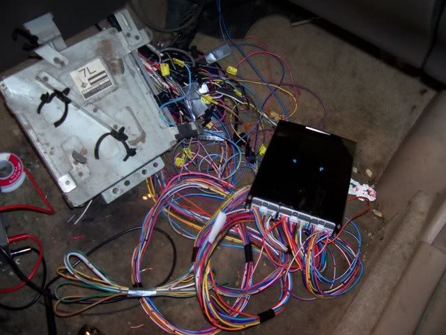
Bump to the top with a teaser pic, I've been taking pics the whole way through and will do a [small] write-up.
Anyways, I was wondering if someone that is bored could maybe help me out so I know if I am going to run into problems later tonight when I start soldering away at the 150 or so connections....
The car is a '99 a/t fed-spec harness, the ecu that I raped for the connector was a '98 i30 a/t, and the harness that I am off to the junkyard to hack is from a......... errr, doubt I'll luck out and find a '99 a/t, so it will hopefully be 96-98 a/t.
Anyways, this ecu connector from a '98 a/t, am I going to be missing pins when trying to install it on a '99? Actually, better yet, does anyone have a chart of the pinout differences between 99 and pre 99? That would be sweet, would save me some time, as you can see I've got alot of labeling ahead of me..........

Thread Starter
Joined: Jul 2002
Posts: 2,063
From: Reno, NV
Bump to the top with a teaser pic, I've been taking pics the whole way through and will do a [small] write-up.
Anyways, I was wondering if someone that is bored could maybe help me out so I know if I am going to run into problems later tonight when I start soldering away at the 150 or so connections....
The car is a '99 a/t fed-spec harness, the ecu that I raped for the connector was a '98 i30 a/t, and the harness that I am off to the junkyard to hack is from a......... errr, doubt I'll luck out and find a '99 a/t, so it will hopefully be 96-98 a/t.
Anyways, this ecu connector from a '98 a/t, am I going to be missing pins when trying to install it on a '99? Actually, better yet, does anyone have a chart of the pinout differences between 99 and pre 99? That would be sweet, would save me some time, as you can see I've got alot of labeling ahead of me..........
I don't think you'll be missing any, some pins will just be in the wrong location so you will need to move them to the correct spot. I have the FSM's on my computer at home but I'm at work right now and won't be there for quite some time.
Difficulties are not having enough space to make this job easy, so you need to learn to make good connections that aren't bulky. As you solder more connections the wires start to get in the way more. It's all mostly about space. there were a few times where I had joints break, because I didn't do a good job of soldering the first time, and then when I went to resolder it I touched another joint with the soldering gun and desoldered that joint. Just make sure you aren't using lead-free solder, and take your time. Chances are you probably won't finish tonight unless you are really good at soldering.
Last edited by hacim105; Mar 24, 2008 at 11:08 AM.


nervous part is starting the car up and seeing if all is done right


Joined: Oct 2005
Posts: 4,572
From: Middleboro/Carver, Ma

Great work man, I also like your idea of printing out the numbers and taping them to the wires, I was planning on using neon green masking tape with one of those super fine sharpies, but I like your idea much better, and yeah that is so kick-*** with the pinouts.
Last edited by KRRZ350; Mar 24, 2008 at 07:29 PM.

does anyone foresee any problems with wiring up for a 5 speed swapped 4th gen (with the 5 speed ecu) or is everyone basically just buying harnesses/ecu's from whatever they can get their hands on and only using the necessary wires
Joined: Oct 2005
Posts: 4,572
From: Middleboro/Carver, Ma
Well if the car is A/T and you didn't use an a/t harness I believe your spare connectors would be shy a few wires, but if you were doing it for a 5-speed with an a/t harness it wouldn't affect anything, you could use an a/t harness/ecu for the spare connectors no problem. In terms of the p/n code it wouldn't really complicate much and would allow you to run the pin?? right to the engine bay even easier than the tcm harness bypass method, let me know if you want me to dig that thread up.

i would DEFF be interested if you begin making these on the reg. I would get you whatever parts you needed to complete the project. Please let us know if your interested i am in NY.
Joined: Oct 2005
Posts: 4,572
From: Middleboro/Carver, Ma
I'm interested in making more of these (I'm sure other members would as well), but they would be a little on the $teep side, you can pm me for details
RE: '99 differences.....................
I'll have a chart for anyones future reference soon enough, BUT it will be according to the FSM, and according to some the FSM is wrong, I think I can already see that in the crank sensor, I'll need to double check a few things first before saying anything definitive...........
Edited.
Last edited by KRRZ350; Mar 24, 2008 at 10:13 PM.
Joined: Oct 2005
Posts: 4,572
From: Middleboro/Carver, Ma
I don't think you'll be missing any, some pins will just be in the wrong location so you will need to move them to the correct spot. I have the FSM's on my computer at home but I'm at work right now and won't be there for quite some time.
Difficulties are not having enough space to make this job easy, so you need to learn to make good connections that aren't bulky. As you solder more connections the wires start to get in the way more. It's all mostly about space. there were a few times where I had joints break, because I didn't do a good job of soldering the first time, and then when I went to resolder it I touched another joint with the soldering gun and desoldered that joint. Just make sure you aren't using lead-free solder, and take your time. Chances are you probably won't finish tonight unless you are really good at soldering.
Difficulties are not having enough space to make this job easy, so you need to learn to make good connections that aren't bulky. As you solder more connections the wires start to get in the way more. It's all mostly about space. there were a few times where I had joints break, because I didn't do a good job of soldering the first time, and then when I went to resolder it I touched another joint with the soldering gun and desoldered that joint. Just make sure you aren't using lead-free solder, and take your time. Chances are you probably won't finish tonight unless you are really good at soldering.
And yeah, I was hoping to at least have all the wires labeled before sleepytime, but that's not going to happen. No worries about the lead-free bs, also F the guns, I have one of those $20 radio-shack butane ones, that thing is the shiz, as well as the auto crimpers. But I can already see how space would start to be a huge concern and it will begin to become a hairy mess at the end, it's so tempting and would make it much easier if I could leave the wire long and just bundle it up afterwards. But that isn't going to happen because I want to reduce the risk of interference any way I can, that is my main and only concern with this project. It was also a concern with the guy at the electronics repair shop that did my ecu connector, I'm probably going to wrap the everliving **** out of several sensors, allthough I'm not sure if that cuts down on interference or not
 Anyone else have any thoughts re: interference


But no 165 bucks isnt bad. im sure you can sourced cheaper though.But then again i know how much it really sucks soldering all of those. but mine looks like a beast compared to that lol. Wish i would of used new wires instead of the old *** harness wires that broke off all the time.
Even just soldering all those wires back together was a royal pia. Man i was so excited when i got all my pins done i was like ok wires will be easy. yeah they were easy just very time consuming!!!! I am seriously so sick of soldering i never want to do it again!
So how much you thinking you going to sell for(ballpark)?
Last edited by Product_Of_Korea; Mar 25, 2008 at 02:54 AM.
Thread Starter
Joined: Jul 2002
Posts: 2,063
From: Reno, NV
Wow, that is some serious wiring! But I'm glad you were able to get the job done.
When I first did the project I offered to do it for a couple guys for about $100 for the labor and then they never responded back. So I never even pursued selling my services. But I would definitely be willing to do it for anyone that is interested.
Last edited by hacim105; Mar 25, 2008 at 10:16 AM.

awesome work, i was planning on doing the same thing
another way of doing it would be to just make a bypass harness at the eu end, thats what i ended up doing, for some reason all the ends going into the eu happen to be the same harnesses that are used to install aftermarket radios. i know its not the same thing, but its very easy to just pull the eu out and swap the bypass in, since everything is in my glovebox, its super easy. esp since my eu keeps eating my #6 coil.
just my $.02
Thread Starter
Joined: Jul 2002
Posts: 2,063
From: Reno, NV
awesome work, i was planning on doing the same thing
another way of doing it would be to just make a bypass harness at the eu end, thats what i ended up doing, for some reason all the ends going into the eu happen to be the same harnesses that are used to install aftermarket radios. i know its not the same thing, but its very easy to just pull the eu out and swap the bypass in, since everything is in my glovebox, its super easy. esp since my eu keeps eating my #6 coil.
just my $.02
another way of doing it would be to just make a bypass harness at the eu end, thats what i ended up doing, for some reason all the ends going into the eu happen to be the same harnesses that are used to install aftermarket radios. i know its not the same thing, but its very easy to just pull the eu out and swap the bypass in, since everything is in my glovebox, its super easy. esp since my eu keeps eating my #6 coil.
just my $.02
I had previously wired in a SAFC-II and that was by no means easy with the constricted space and with the wires so tight together. Aside from that there was one wire that I ended up having to attach an extra piece to because I accidently cut it instead of just stripping it.
So when I thought about installing the EU and all the work it would take to wire it into the car with about triple the amount of wires of the SAFC, I was not about to do that. So I made a plug n play connector to help. And I'm sure glad I did. And everything works like a charm.
That is another idea but I think the main reason for making a this connector is so that you don't have to alter the main harness in any way. I don't believe it's all just about plug n play, at least it wasn't for me.
I had previously wired in a SAFC-II and that was by no means easy with the constricted space and with the wires so tight together. Aside from that there was one wire that I ended up having to attach an extra piece to because I accidently cut it instead of just stripping it.
So when I thought about installing the EU and all the work it would take to wire it into the car with about triple the amount of wires of the SAFC, I was not about to do that. So I made a plug n play connector to help. And I'm sure glad I did. And everything works like a charm.
wish i could say the same for my harness

but yeah besides the plug and play features of making the harness you dont have to chop up your existing wiring like this
i have to admit thou hardwiring it in wasnt as hard as i thought it was going to be. i had to pretty much sit indian style on the ground while working on it. but i do regret hacking up my wiring
but ill live

Okay, Im in a similiar situatuion so sorry about the thread jack. I didnt want to create another Emanage harness thread.
So my issue is this and hopefully someone can help.
I have created my own harness as well, similiar to the ones pictured above.
Now when I plugged it into the main harness and between the ecu and started the car, everything went fine. Car idled fine, and drove fine. After I drove it around for a bit I got a CEL. Pulled the code and its for EGR Temp Sensor.
Now I pulled up the pin diagram for this to see if maybe a didnt solder it correctly or etc. and its not listed.
Anyone know which one it is so I can inspect it?
Thread Starter
Joined: Jul 2002
Posts: 2,063
From: Reno, NV
Okay, Im in a similiar situatuion so sorry about the thread jack. I didnt want to create another Emanage harness thread.
So my issue is this and hopefully someone can help.
I have created my own harness as well, similiar to the ones pictured above.
Now when I plugged it into the main harness and between the ecu and started the car, everything went fine. Car idled fine, and drove fine. After I drove it around for a bit I got a CEL. Pulled the code and its for EGR Temp Sensor.
Now I pulled up the pin diagram for this to see if maybe a didnt solder it correctly or etc. and its not listed.
Anyone know which one it is so I can inspect it?
So my issue is this and hopefully someone can help.
I have created my own harness as well, similiar to the ones pictured above.
Now when I plugged it into the main harness and between the ecu and started the car, everything went fine. Car idled fine, and drove fine. After I drove it around for a bit I got a CEL. Pulled the code and its for EGR Temp Sensor.
Now I pulled up the pin diagram for this to see if maybe a didnt solder it correctly or etc. and its not listed.
Anyone know which one it is so I can inspect it?
For that code, the year does not really matter as long as it is 96-99. He would have a lot more codes if he was running a 95 harness on a 96+ ecu.
The DTC is 1401 and the pin is 63.
Thread Starter
Joined: Jul 2002
Posts: 2,063
From: Reno, NV
I just remember that I switched from a 96 ecu to a 97 and there was one wire I had to move. But i couldn't remember what one it was so I was wondering if he had the same problem.
I can find out later though.
Last edited by Flava_24/7; Apr 8, 2008 at 01:35 PM.
Thanks

