

Completed 3.5IM install with pics of custom IACV/TB mounting plates on intake pipe


Completed 3.5IM install with pics of custom IACV/TB mounting plates on intake pipe
Acknowledgements: special thanks to Jeremy (maxmaxima91) for the fabrication and CNC machine work in his garage, John for the Inventor CAD drawings done at midnight when we discovered we needed a spacer, and Mike for wiring in my injectors and making them look OEM while I was working on other stuff.
So I've been running a 3.0 stock intake manifold and lower intake manifold (USIM and LIM) for the last year and a half on my 3.5 swapped car, with the mismatched ports and all. I couldn't get a clear pic of the port mismatch between the 3.5 heads and 3.0 LIM, but lets just say it's bad. They are not even close to the same shape. One is a long oval and the other is way closer to a circle. So there was probably 3-4mm of mismatch on either side of the intake ports lol not ideal.
So I finally got around to installing the 3.5IM and 3.5 LIM. Things got complicated though because I am using a 3.0 rear valve cover. the 3.0 rear valve cover is taller, and 3.0 rear coil packs are taller, and the coilpack mounting bosses are taller. this came to bite me in the azz when installing the 3.5 IM. I couldn't get the 3.5IM to mount onto the 3.5 LIM because the rear coil packs were too tall.
First attempt was to use 3.5 rear coil pack top part (the part with the circuitry, ignitor, harness connector, etc) with a 3.0 coilpack stalk. they are interchangeable in case anyone was wondering. you can pop the "stalk" (the part that goes down in the head and engages the spark plug right off the 3.0 coilpack and stick it on the 3.5 coilpack. this hybrid coilpack was still too tall though, really didn't end up being much more clearance than the 3.0 rear coil pack had. then I tried using a stock 3.0 front coil pack. this was still way too tall though it was better. so it came time to make some custom stuff. my buddy just happened to have the .75" thick phenolic plastic slab that I bought a couple years ago still laying around. so my buddy john whipped up a phenolic spacer using Inventor and we machined it out on my buddy's CNC router that he has in his garage. Here are pics of that process.
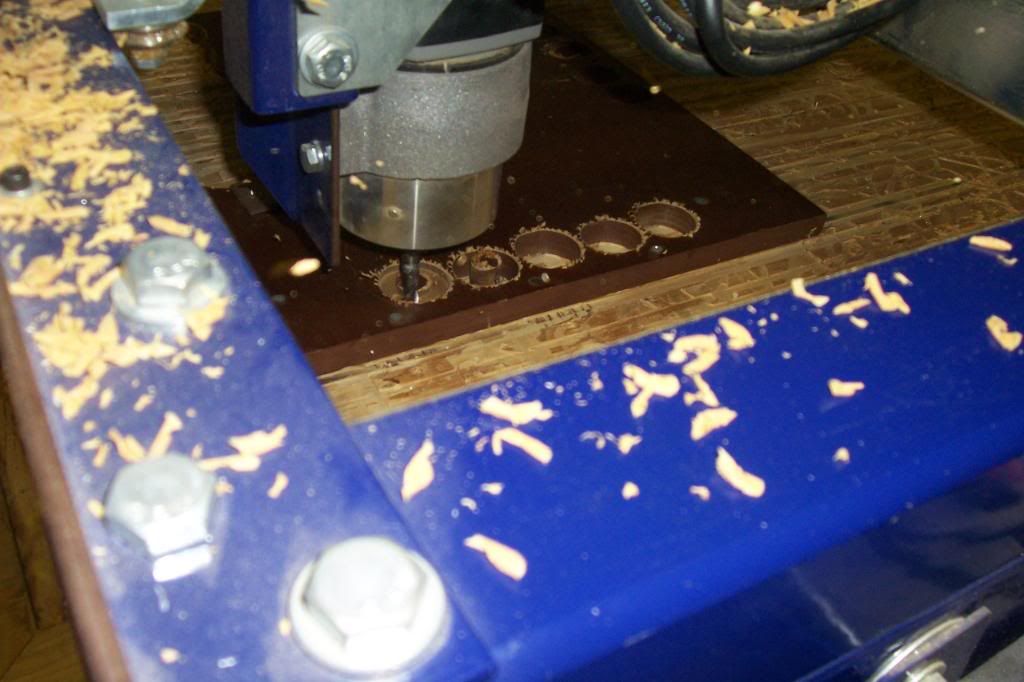
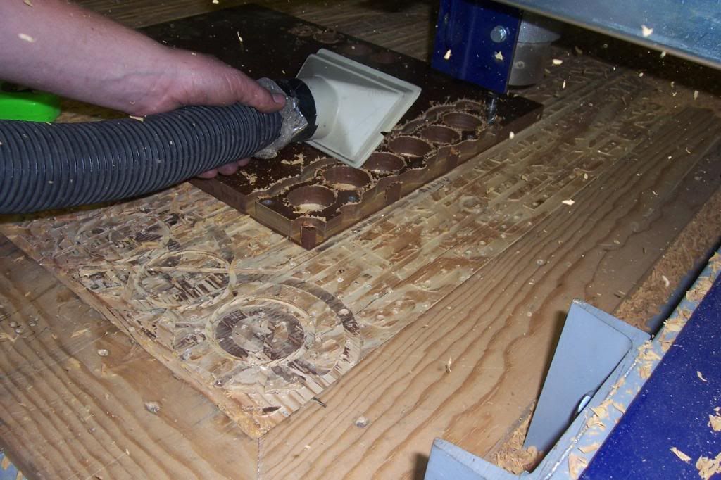
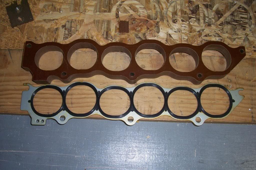
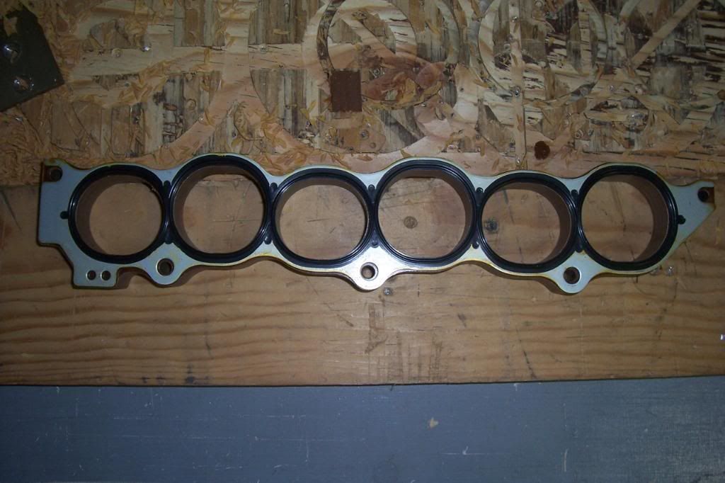
All done, with the gasket that we used as a template. Perfect match.
So I've been running a 3.0 stock intake manifold and lower intake manifold (USIM and LIM) for the last year and a half on my 3.5 swapped car, with the mismatched ports and all. I couldn't get a clear pic of the port mismatch between the 3.5 heads and 3.0 LIM, but lets just say it's bad. They are not even close to the same shape. One is a long oval and the other is way closer to a circle. So there was probably 3-4mm of mismatch on either side of the intake ports lol not ideal.
So I finally got around to installing the 3.5IM and 3.5 LIM. Things got complicated though because I am using a 3.0 rear valve cover. the 3.0 rear valve cover is taller, and 3.0 rear coil packs are taller, and the coilpack mounting bosses are taller. this came to bite me in the azz when installing the 3.5 IM. I couldn't get the 3.5IM to mount onto the 3.5 LIM because the rear coil packs were too tall.
First attempt was to use 3.5 rear coil pack top part (the part with the circuitry, ignitor, harness connector, etc) with a 3.0 coilpack stalk. they are interchangeable in case anyone was wondering. you can pop the "stalk" (the part that goes down in the head and engages the spark plug right off the 3.0 coilpack and stick it on the 3.5 coilpack. this hybrid coilpack was still too tall though, really didn't end up being much more clearance than the 3.0 rear coil pack had. then I tried using a stock 3.0 front coil pack. this was still way too tall though it was better. so it came time to make some custom stuff. my buddy just happened to have the .75" thick phenolic plastic slab that I bought a couple years ago still laying around. so my buddy john whipped up a phenolic spacer using Inventor and we machined it out on my buddy's CNC router that he has in his garage. Here are pics of that process.
All done, with the gasket that we used as a template. Perfect match.
Last edited by Nealoc187; Jul 13, 2009 at 10:56 PM.
Earlier in the evening we had completed a custom pipe and adaptor plate setup. We decided not to use the 3.5 throttle body even though it is much bigger than the 3.0 TB. I didn't want to have to modify the TB. Much easier to just make a simple adaptor. We decided to incorporate an IACV mounting plate into the new TB adaptor pipe as well.
We sort of without thinking decided to mount it on an angle for clearance issues, not thinking about the fact that it was right smack in the place where our throttle cable needed to mount. So we ended up having to rig a bit of a workaround for the throttle cable as well. I didn't get any pics of it after completion because it was late and we still had a bunch of stuff to do , but I do have pics of it installed in my nasty, dirty engine bay. Forgive the mess and forgive the TPS wiring. I realized when I was wiring up everything for final assembly that my TPS harnesses wouldn't reach, so at FIVE am, 50 miles from home, about 17 hours after I started working on this, I decided to extend that wiring in the quickest, dirtiest wiring job ever known to man. 10 minutes later I had the ugly wire extensions complete lol. Anyways, here's what the finished product looks like. Made installing the TB and IACV a breeze. If we had it to do over we would mount the IACV at a different angle (perhaps on the back side and move my FPR) so as to avoid having the throttle cable bracket sticking out at that funny angle. It works like a charm though.
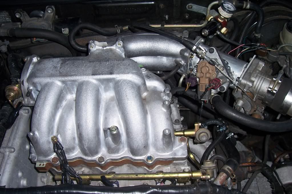
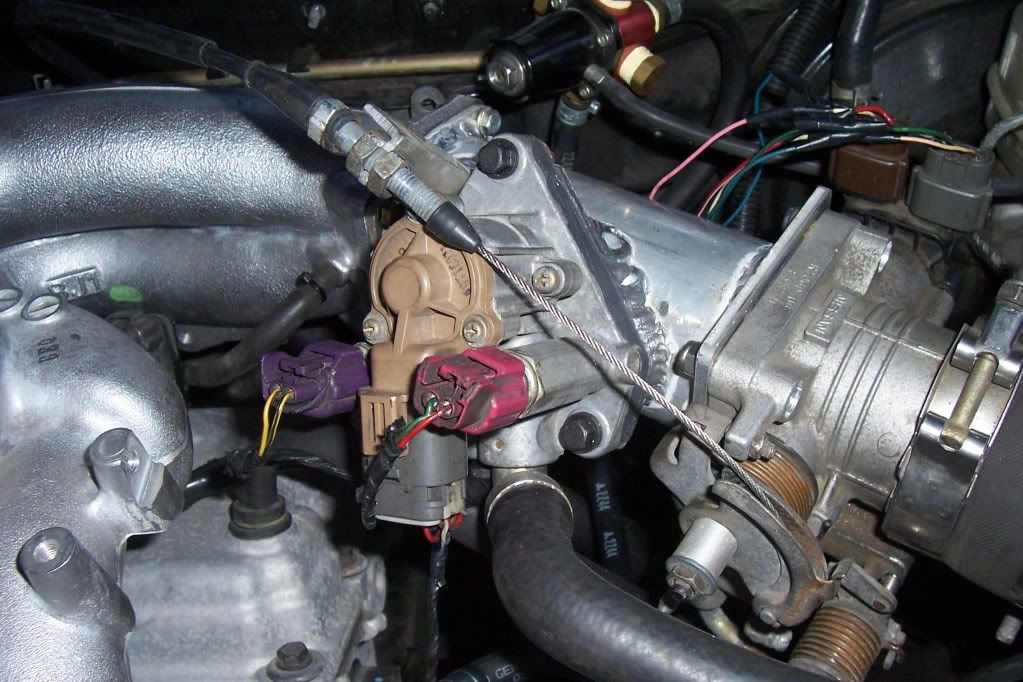
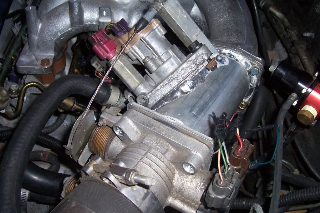
We sort of without thinking decided to mount it on an angle for clearance issues, not thinking about the fact that it was right smack in the place where our throttle cable needed to mount. So we ended up having to rig a bit of a workaround for the throttle cable as well. I didn't get any pics of it after completion because it was late and we still had a bunch of stuff to do , but I do have pics of it installed in my nasty, dirty engine bay. Forgive the mess and forgive the TPS wiring. I realized when I was wiring up everything for final assembly that my TPS harnesses wouldn't reach, so at FIVE am, 50 miles from home, about 17 hours after I started working on this, I decided to extend that wiring in the quickest, dirtiest wiring job ever known to man. 10 minutes later I had the ugly wire extensions complete lol. Anyways, here's what the finished product looks like. Made installing the TB and IACV a breeze. If we had it to do over we would mount the IACV at a different angle (perhaps on the back side and move my FPR) so as to avoid having the throttle cable bracket sticking out at that funny angle. It works like a charm though.
Driving impressions:
Well let me preface this by saying that my laptop has died and I've lost my tuning ability for emanage right now. I was changing from 410cc side feeds to stock 270cc top feeds, so needless to say I was going to be lean. We adjusted my FPR to make the fuel pressure as high as we could, but still wasn't enough for WOT (it was like 14.0 at WOT, but perfectly fine for driving around.)
Then I remember that emanage blue has those coarse tuning ***** on the front of it. I had never messed with these before but I just turned them all full rich and viola, mid 12s AFR in the midrange RPMs and low 12s in the high RPM range. very rough, but safe for WOT. I also have not yet installed the RPM switch to make the VIAS work, so I just tried it with it tied open and closed.
First impression after getting the AFR to where I could go WOT through the gears... holy cow this thing feels fast. There is a huge difference between the upper RPM pull when I had the USIM vs now with the 3.5IM, even with the VIAS closed (honestly, I can't really tell a difference between VIAS closed and open, but I can definitely tell that it's faster than with the USIM.)
This week I've got headers that should be arriving on Tuesday and supposedly my prototype Bikirom USB programmable 4th gen ECU should be arriving this week as well. I cant wait. I'm still running stock 3.0 timing because you can't advance timing with my EB, when I do the car just dies. I can't wait to get to the track with headers, the 3.5IM working as it should with RPM switch, and the ECU with a proper tune, both advanced timing and proper AFR. The car's going to be a real screamer even with the stock 3.0 cams I have in it.
Last edited by Nealoc187; Jul 13, 2009 at 10:57 PM.
http://forums.maxima.org/supercharge...ld-thread.html


Last edited by Nealoc187; Jul 13, 2009 at 11:07 PM.

dang bro! great work! i really wished i could have hung out with you guys and worked on it! i can't wait to see what you get at the track! you still better take me for a ride before i leave chicago! lol .....
good work bro!
good work bro!


Yeah Jeremy plans to. When he produces them to sell though we will have the IACV placement different so that it doesn't interfere with putting the throttle cable bracket where we want it, and also the flanges will be made out of thicker aluminum. Having these would save tons of headache for future 3.5 swappers though. Instead of hours ****ing around with a bunch of adaptor plates and TB modification and all that crap, 5 minutes to bolt the adaptor pipe in and you're done. Takes hours and hours off of the 3.5 swap process and makes it look better too imho.

Damn thats impressive. I agree, that extension with the adapter is money. For the 3.5 swap and the 00VI... best part is, you wouldn't have to change anything for the 00VI version except the plate that bolts to the UIM.
Last edited by MOHFpro90; Jul 14, 2009 at 03:37 PM.

Joined: Oct 2005
Posts: 4,572
From: Middleboro/Carver, Ma
I'm disappointed that you didn't hog out the heads and lim and put an '00vi on there............
But, DAMN, nice work, I don't know what I like more: the spacer, or that tube. I think that tube. You couldn't be more correct about the PITA relocating the iacv makes for, as well as subpar results in the end.
But, DAMN, nice work, I don't know what I like more: the spacer, or that tube. I think that tube. You couldn't be more correct about the PITA relocating the iacv makes for, as well as subpar results in the end.
I considered that but decided that just doing the spacer would be easier and I'm not willing to really spend any more money on NA stuff, I've got a turbo setup to be working on hehe. I've had this IM sitting around for the last 2 years or whatever so I decided to finally install it.


I want CNC equipment in my garage 
Interesting design for the IACV mounting. It doesn't look all that bad, just needs a little tidying up with the wiring.
I'd probably look for somewhere else to put those grounds, the timing cover would likely be better than the UIM. With that phenolic spacer there's not much metal-metal contact going on there, pretty much just the bolts. Just MO.
Also, how the hell is that TB being held on? Looks like magic or something.
Interesting design for the IACV mounting. It doesn't look all that bad, just needs a little tidying up with the wiring.
I'd probably look for somewhere else to put those grounds, the timing cover would likely be better than the UIM. With that phenolic spacer there's not much metal-metal contact going on there, pretty much just the bolts. Just MO.
Also, how the hell is that TB being held on?
Looks like magic or something.
Last edited by pmohr; Jul 25, 2009 at 10:04 PM.
Look at the last pic with the TB and Iacv. Looks like threaded screws and a nut on the other side of the TB.
I saw that, but the bolt holes in the A32 TB aren't stepped, they're straight through; unless it's some kind of rubber expansion fitting, I don't see how it could be bolted on.
I know what your saying.....
Even if there was a rubber spacer type thing one wouldnt think that is a good way to mate the TB to the adapter.
But it does kind of looks like he hogged out the TB holes so there would be a step for the bolt to rest on
The TPS wiring is cleaned up and looks OEM now.
My buddy just countersunk the holes and those phillips head bolts just go into nuts on the back side of the flange that you can't see.

Those grounds won't reach to the closest hole on the valve cover believe me I tried, I could make them reach but they were under so much tension they those wires would break in no time. I would have to extend them. Putting them on the manifold has had no ill effects. :shrug:
My buddy just countersunk the holes and those phillips head bolts just go into nuts on the back side of the flange that you can't see.
Those grounds won't reach to the closest hole on the valve cover believe me I tried, I could make them reach but they were under so much tension they those wires would break in no time. I would have to extend them. Putting them on the manifold has had no ill effects. :shrug:
Last edited by Nealoc187; Jul 26, 2009 at 08:10 PM.

Thread
Thread Starter
Forum
Replies
Last Post
vingodine
5th Generation Classifieds (2000-2003)
45
May 21, 2016 12:46 PM
MaximaDrvr
7th Generation Maxima (2009-2015)
16
Aug 19, 2015 08:20 PM
Team STILLEN
Autocrossing and Road Course Racing
0
Aug 10, 2015 04:29 PM