

shadyonedeath's 00vi swap - 1999 SE-L


shadyonedeath's 00vi swap - 1999 SE-L
Another one fellas. And its my turn to give back to the community. I don't mean to re-invent the wheel but i figured i'd include my own tips on things that weren't covered in other members threads. Just some simple stuff thats overlooked but crucial for those not mechanically inclined. This thread will provide lots of pictures and step by step procedures. Will be updated often as necessary. Thanks for looking. Feedback and constructive criticism is highly welcomed.
Materials:
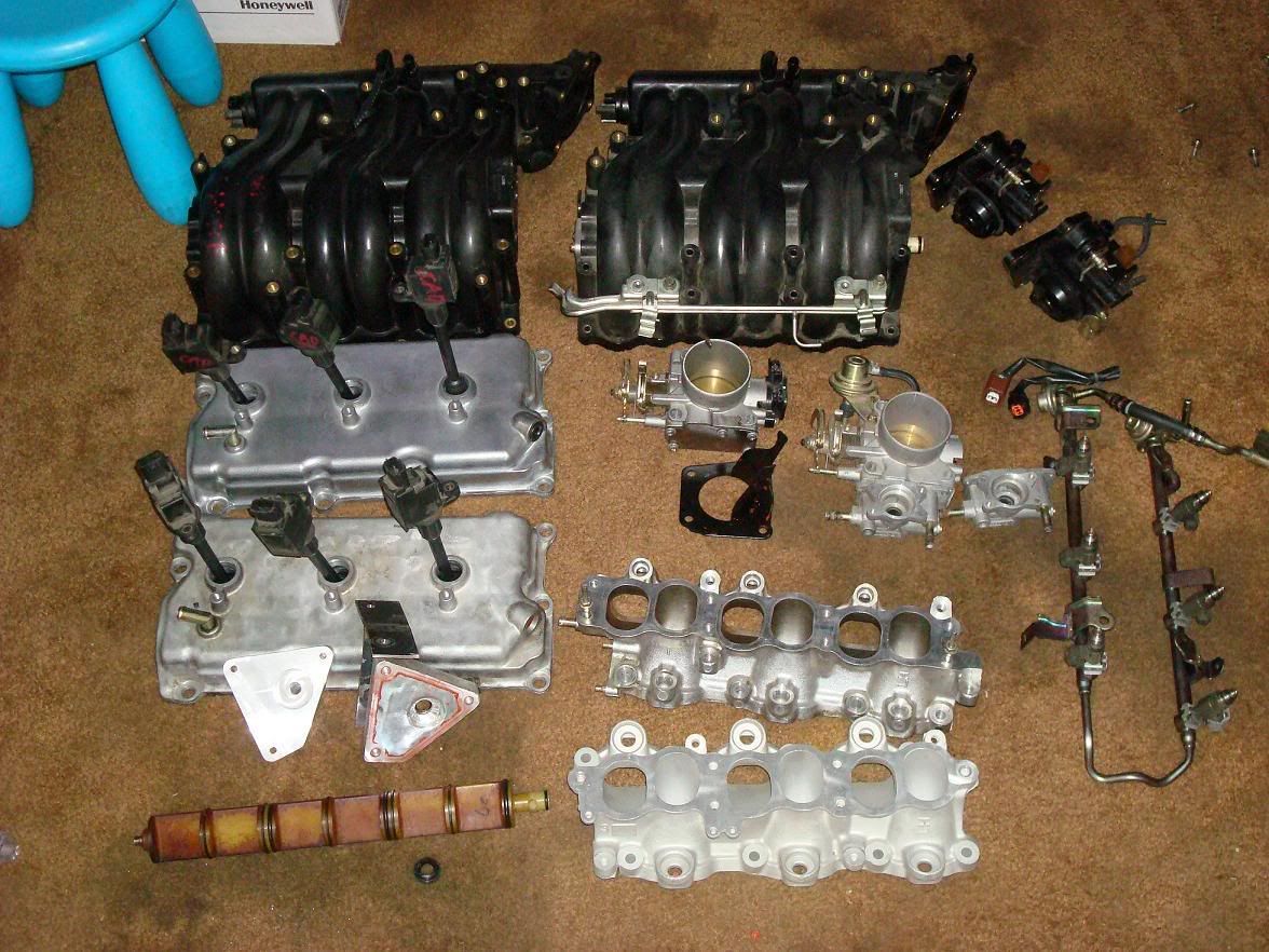
Don't ask. I collected parts for both 00vi setup options. 4th gen LIM setup and all 5th gen LIM setup. Both of them would have used a 4th gen IACV and adapter. I am going with 5th gen lower because i decided the UIM was designed for the 5th gen lower, and i don't mind tuning it when using the 5th gen fuel rails.
MY Swap project:
-5th gen Upper intake manifold (w/ mounting hardware, throttle cable bracket and PCV hard lines)
-5th gen Lower intake manifold
-5th gen fuel rail, injectors, NO adapter. (i used the existing line/barb and didn't need a adapter)
-5th gen Throttle Body
-5th gen Rear valve cover
-5th gen Rear Coil packs
-IACV Adapter
-4th gen IACV
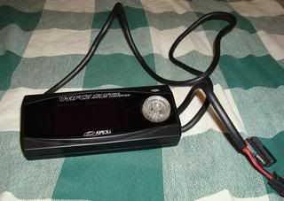
-Apexi VAFC2 (for tuning and Activation point)
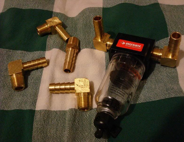
-Brass elbows, All threaded 1/4". Barbs = (2) 3/8" for Brake booster and EVAP and (1) 1/2" for IACV)
Prepping the UIM
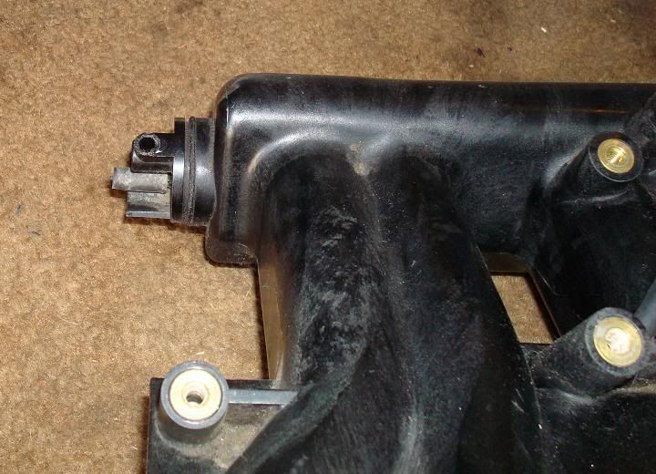
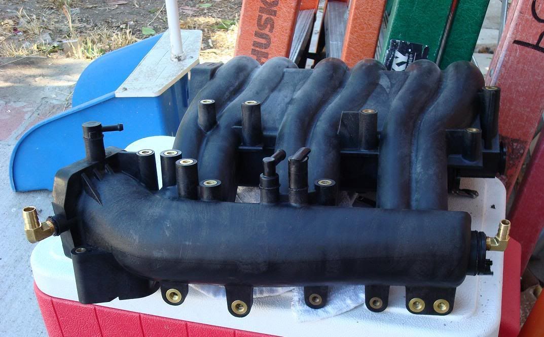
If you were like me, your junkyard/delivery man wasn't too friendly with the UIM. As you can see my first UIM has the majority of nipples broken. Good thing we they're inadequate for our 4th gen vacuum lines and we need to replace them anyway...
Here is what I will be using.
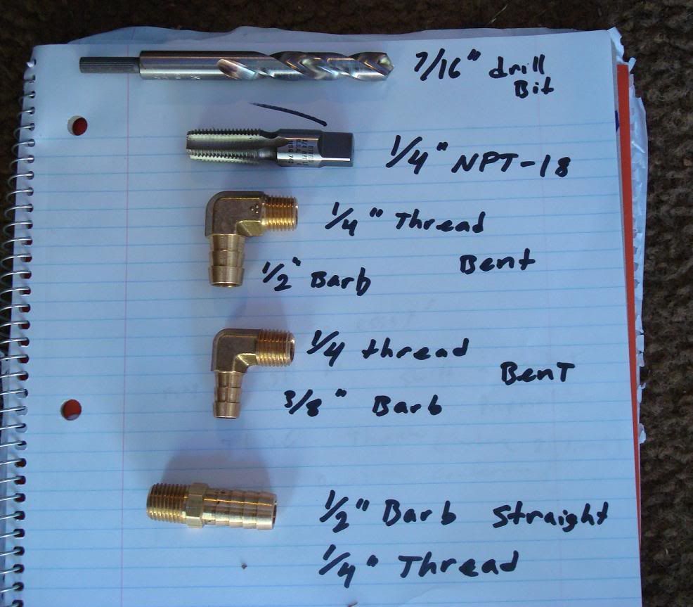
Materials: from top to bottom of picture
-7/16" drill bit
-1/4" NPT-18 tap (available for sale, apparently my old man stocked up back in the day. They're new and i have 1/4", 3/8", and 1/2")
-Brass elbows All threaded 1/4".
Barbs vary from:
(2) 3/8" 90 degree elbows for Brake booster and EVAP
(1) 1/2" 90 degree elbows for IACV
Note: Ignore the Straight brass fitting in the picture. Didnt use it. 90 degree bent elbows work best. I used two 3/8" x 1/4" elbows and one 1/2" x 1/4 elbow.
Edit: The straight 1/2" barb is for the IACV adapter.
Materials:
Don't ask. I collected parts for both 00vi setup options. 4th gen LIM setup and all 5th gen LIM setup. Both of them would have used a 4th gen IACV and adapter. I am going with 5th gen lower because i decided the UIM was designed for the 5th gen lower, and i don't mind tuning it when using the 5th gen fuel rails.
MY Swap project:
-5th gen Upper intake manifold (w/ mounting hardware, throttle cable bracket and PCV hard lines)
-5th gen Lower intake manifold
-5th gen fuel rail, injectors, NO adapter. (i used the existing line/barb and didn't need a adapter)
-5th gen Throttle Body
-5th gen Rear valve cover
-5th gen Rear Coil packs
-IACV Adapter
-4th gen IACV
-Apexi VAFC2 (for tuning and Activation point)
-Brass elbows, All threaded 1/4". Barbs = (2) 3/8" for Brake booster and EVAP and (1) 1/2" for IACV)
Prepping the UIM
If you were like me, your junkyard/delivery man wasn't too friendly with the UIM. As you can see my first UIM has the majority of nipples broken. Good thing we they're inadequate for our 4th gen vacuum lines and we need to replace them anyway...
Here is what I will be using.
Materials: from top to bottom of picture
-7/16" drill bit
-1/4" NPT-18 tap (available for sale, apparently my old man stocked up back in the day. They're new and i have 1/4", 3/8", and 1/2")
-Brass elbows All threaded 1/4".
Barbs vary from:
(2) 3/8" 90 degree elbows for Brake booster and EVAP
(1) 1/2" 90 degree elbows for IACV
Note: Ignore the Straight brass fitting in the picture. Didnt use it. 90 degree bent elbows work best. I used two 3/8" x 1/4" elbows and one 1/2" x 1/4 elbow.
Edit: The straight 1/2" barb is for the IACV adapter.
Last edited by shadyonedeath; Aug 2, 2009 at 11:50 PM.
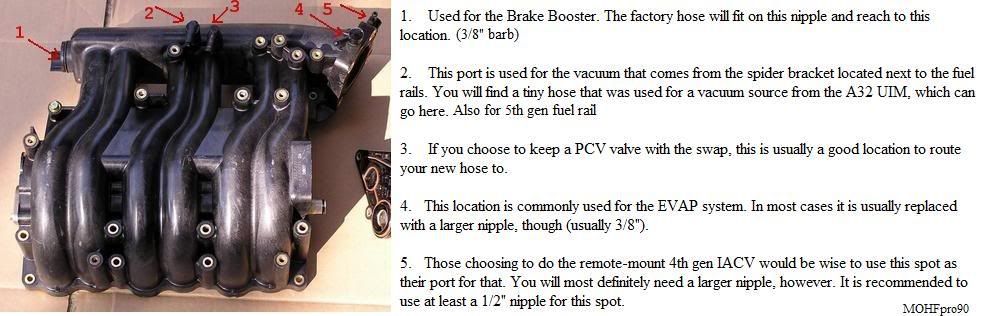
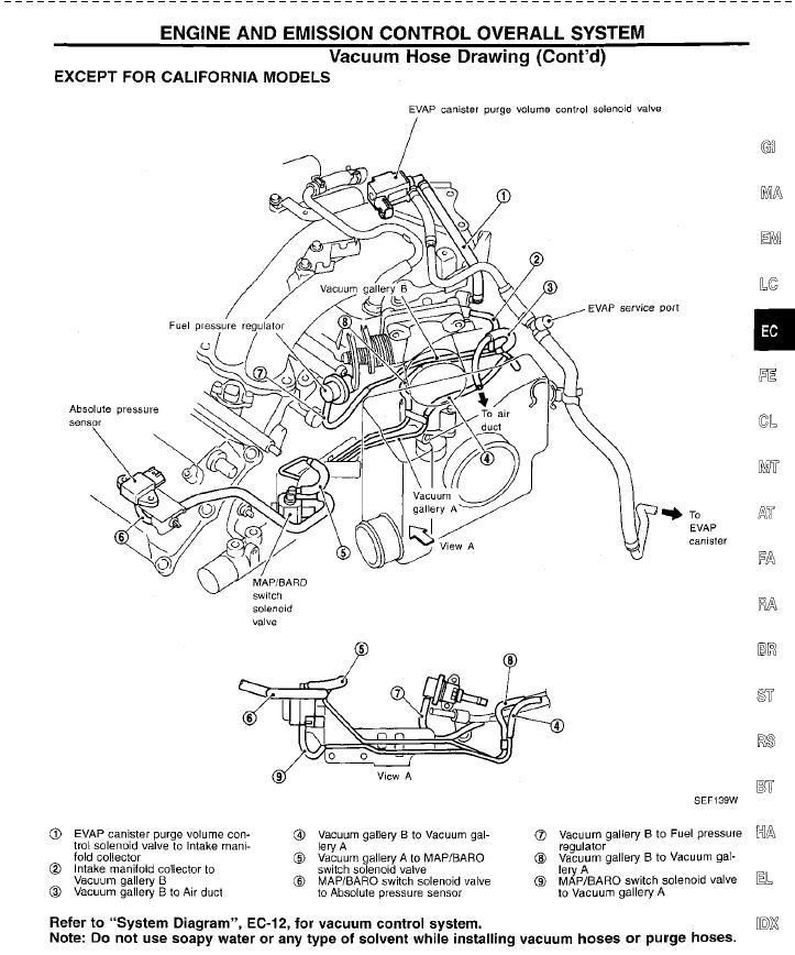
Lets start with the EVAP line located on TOP of the UIM where the Throttle body bolts up. Number (4) on the Diagram.
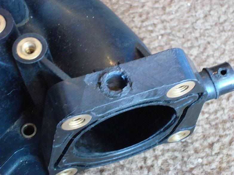
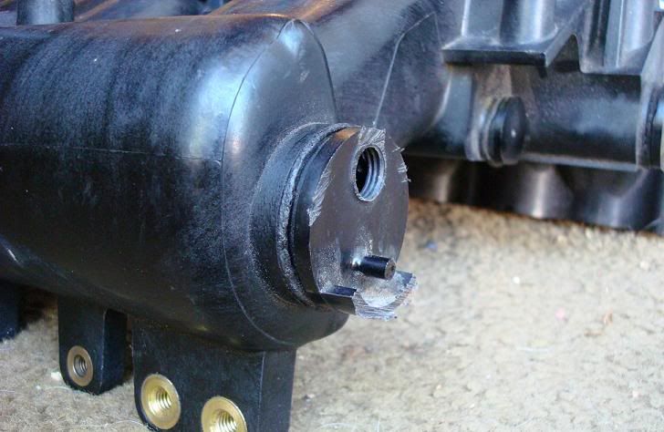
Damaged tower but still has plenty of meat to work with. First step, drill it out using a smaller 3/8" drill bit, and move up to a 7/16" bit to reduce stress. The 1/4 NPT-18 tap requires a 7/16" hole.
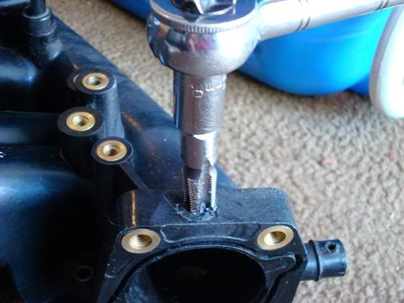
Note: Either this plastic material is super fragile or my tap was razor sharp, but it cut through like butter. Make sure you know how deep your tap has gone so you don't accidentally ruin your threads by over-turning it.
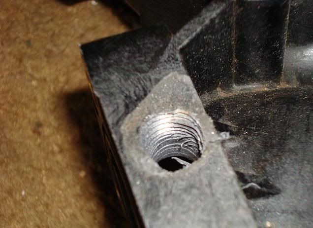
Result. Make sure you use some tweezers to pluck off excess plastic and prevent it from getting sucked in to your car later. Once its all clean, insert your 3/8" barb x 1/4" threaded brass fitting here, and your done. I also used RED permanent loctite (thread lock) to seal it up real good. You will probably want to use some RTV instead of loctite. I didnt, but i will if i encounter any leaks during the install.
Damaged tower but still has plenty of meat to work with. First step, drill it out using a smaller 3/8" drill bit, and move up to a 7/16" bit to reduce stress. The 1/4 NPT-18 tap requires a 7/16" hole.
Note: Either this plastic material is super fragile or my tap was razor sharp, but it cut through like butter. Make sure you know how deep your tap has gone so you don't accidentally ruin your threads by over-turning it.
Result. Make sure you use some tweezers to pluck off excess plastic and prevent it from getting sucked in to your car later. Once its all clean, insert your 3/8" barb x 1/4" threaded brass fitting here, and your done. I also used RED permanent loctite (thread lock) to seal it up real good. You will probably want to use some RTV instead of loctite. I didnt, but i will if i encounter any leaks during the install.
Last edited by shadyonedeath; Aug 2, 2009 at 11:54 PM.
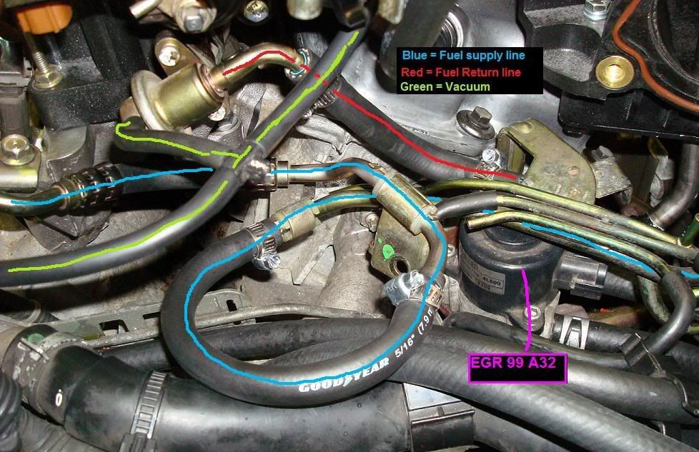
Brake booster line
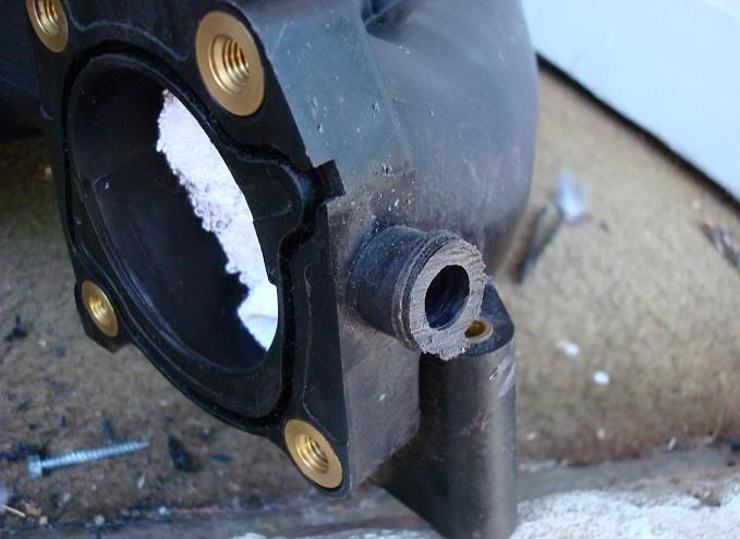
Next, the brake booster line. Number (1) in the diagram.. Cut the existing nipple flush with the wall of the manifold and drill using 7/16" bit. Careful, don't go too deep, not a lot of meat in there, and you'll quickly hit a wall inside the manifold. Just drill enough to widen the hole for tapping.

I then pulled out the rubber cap covering a small nipple underneath the brake booster nipple and cut it away enough to allow my brass fitting to screw in. Don't cut it all the way to the wall like the brake booster nipple above it, leave some nipple there and cover it back up with the rubber cap along with some sealant. This will avoid the hassle of sealing it up with something gay like JB weld and getting sucked in.
I then pulled out the rubber cap covering a small nipple underneath the brake booster nipple and cut it away enough to allow my brass fitting to screw in. Don't cut it all the way to the wall like the brake booster nipple above it, leave some nipple there and cover it back up with the rubber cap along with some sealant. This will avoid the hassle of sealing it up with something gay like JB weld and getting sucked in.
Last edited by shadyonedeath; Aug 1, 2009 at 08:36 PM.
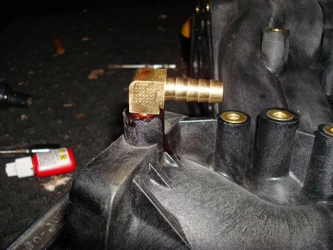
IACV line
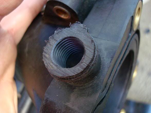
Last, the IACV line, port 5 in the diagram. The brass elbow used is a 90 degree 1/2" barb x 1/4" threaded brass fitting that's required to give enough air flow to the IACV adapter to prevent idle issues. I used a hacksaw to cut the tower behind the existing nipple. I then used my smaller 3/8" drill bit to enlarge the hole, followed by 7/16" drill bit. I then used my tap, and ended with the brass fitting and some loctite.
Edit: Don't use Loctite. When it dries, it gets hard. Hard = cracking if you later want to re-position the nipple in a different angle. You dont want pieces of loctite in your engine. If i were to do it again i'd use High Temp RTV. Its orange and flexible when hard.

Note: These brass fittings are a ***** to get in. Once you've twisted beyond the strength of your hand, use a wrench to torque it in there.
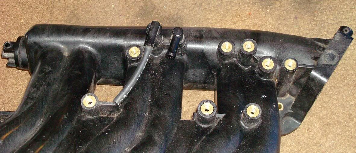
Both fittings shown. The reason the top tower for the EVAP is still in tact is because i need to get another 90 degree 3/8 barbed elbow but the hardware store is closed. I WAS going to use the straight one but the hole that supplies that tower with vacuum is too small. I need to cut it off completely and enlarge the hole all the way through the manifold. Also, the process shown in the first drilling of the EVAP line was from my 2nd manifold which i will be selling. I prepped both manifolds for threads but only installed nipples in one.
Update: Top tower fitting installed
Edit: Don't use Loctite. When it dries, it gets hard. Hard = cracking if you later want to re-position the nipple in a different angle. You dont want pieces of loctite in your engine. If i were to do it again i'd use High Temp RTV. Its orange and flexible when hard.
Note: These brass fittings are a ***** to get in. Once you've twisted beyond the strength of your hand, use a wrench to torque it in there.
Both fittings shown. The reason the top tower for the EVAP is still in tact is because i need to get another 90 degree 3/8 barbed elbow but the hardware store is closed. I WAS going to use the straight one but the hole that supplies that tower with vacuum is too small. I need to cut it off completely and enlarge the hole all the way through the manifold. Also, the process shown in the first drilling of the EVAP line was from my 2nd manifold which i will be selling. I prepped both manifolds for threads but only installed nipples in one.
Update: Top tower fitting installed
Last edited by shadyonedeath; Sep 9, 2009 at 04:06 PM.
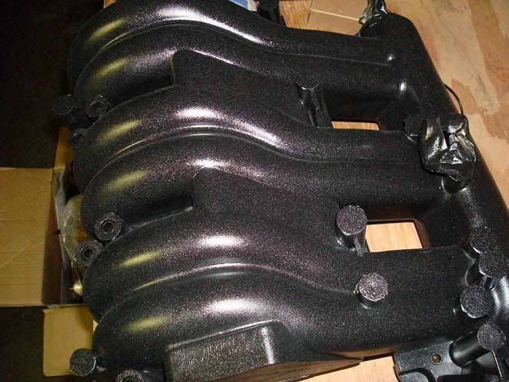
Painting 00vi Upper Manifold
Materials:
-400-800 grit sand paper
-Rubbing alcohol
-Masking/scotch/painters tape
-High Temp engine paint (gloss black)
Process:
-Pretty simple: sand smooth, clean with rubbing alcohol, mask important areas with tape and paint.
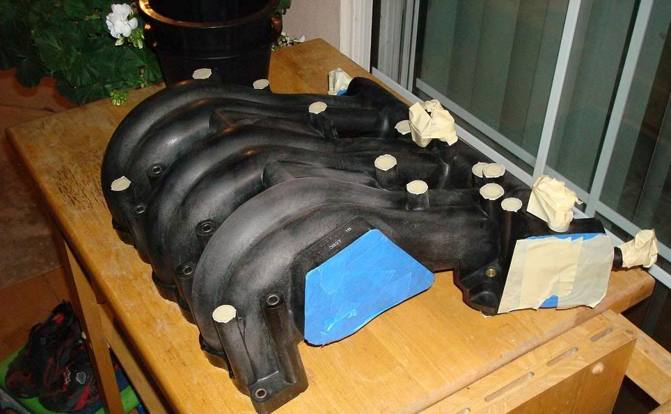
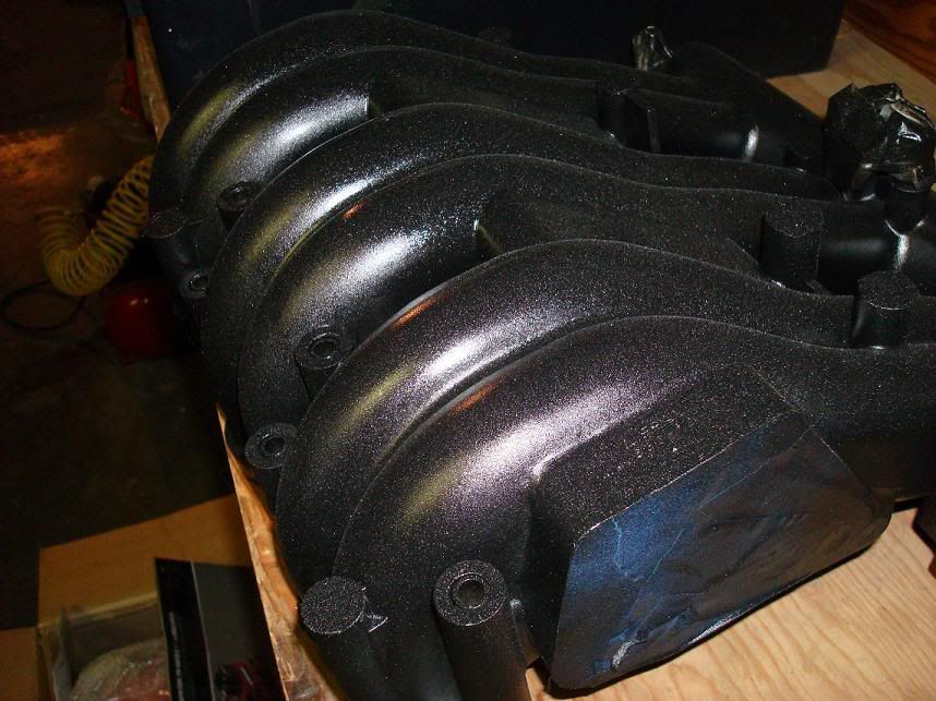
Here I used some left over graphite colored wheel spray paint and "flaked" it from a distance to give it a diff. look.
Materials:
-400-800 grit sand paper
-Rubbing alcohol
-Masking/scotch/painters tape
-High Temp engine paint (gloss black)
Process:
-Pretty simple: sand smooth, clean with rubbing alcohol, mask important areas with tape and paint.
Here I used some left over graphite colored wheel spray paint and "flaked" it from a distance to give it a diff. look.
Last edited by shadyonedeath; Aug 13, 2009 at 09:34 PM.
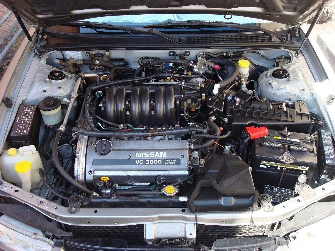
00vi Swap : The Removal
I recommend getting your models Factory service Manual for reference. Search the forum, they're available for download.
If you're attempting the 00vi swap you should be fairly familiar with what needs to be removed and how to remove them. I'll try and go through the basics. Also, before you start, i recommend your protect your fenders with some type of cover between your knees/clothes and the paint. I used some brown wrapping paper and Painters tape to cover both fenders and areas pained near the engine bay. I also recommend you label your hoses and there they go. Use whatever it takes because no matter how good you think your memory is, you WILL lose track of dangling hoses.
A - Battery
B - Air Box
C - Mass Air Flow Sensor MAF (Handle with care...we don't need more problems when troubleshooting your 00vi install)
D - Throttle Body - 4th Gen TB's have a) Throttle Cables, b) Coolant lines (I plugged mine with bolts removed in the process to prevent spilling), c) Connectors (Throttle Position sensors, Brown and Black/Gray) that need to be removed.
E - Electrical log/Harness - This connects to: a) Coil Packs, b) EVAP valve c) EGR temp sensor, d) EGR unit itself, e) Throttle Position sensor. Remove these and the log can be bent out of the way towards passenger side of engine bay.
F - Upper Intake Manifold - Mine had 4 bolts up front towards bumper and 4(?) in the rear attached to mounting brackets. Stick your hand back there and familiarize yourself with the brackets and the number of bolts. Not 100% sure how many there are back there. UIM also has the throttle cables mounted to the bracket, loosen the cables and they slip off the bracket. If your 00vi didnt come with a bracket, avoid removing the cables and just remove the bracket itself and push/tape out of the way. The EVAP valve is also on top of the UIM, remove it and get it out of the way. Your PVC line will also be attached to the UIM, remove the vacuum hose. Behind the UIM, your EGR tube is attached, there are 2 bolts holding it. Under the EGR tube are 2 short coolant lines that run through the UIM. I didnt bother removing mine properly due to the tight space, i just took a knife to the hoses since I replaced the two EGR coolant lines and make a "UIM/Throttle Body coolant bypass". Remember to note which one Runs coolant and which one Returns it, they lead back to the coolant log near the front Valve cover/ Knock sensor connector cable.
G - EVAP valve
H- Not visible in picture but this is where you Idle Air Control Valve is. (IACV)
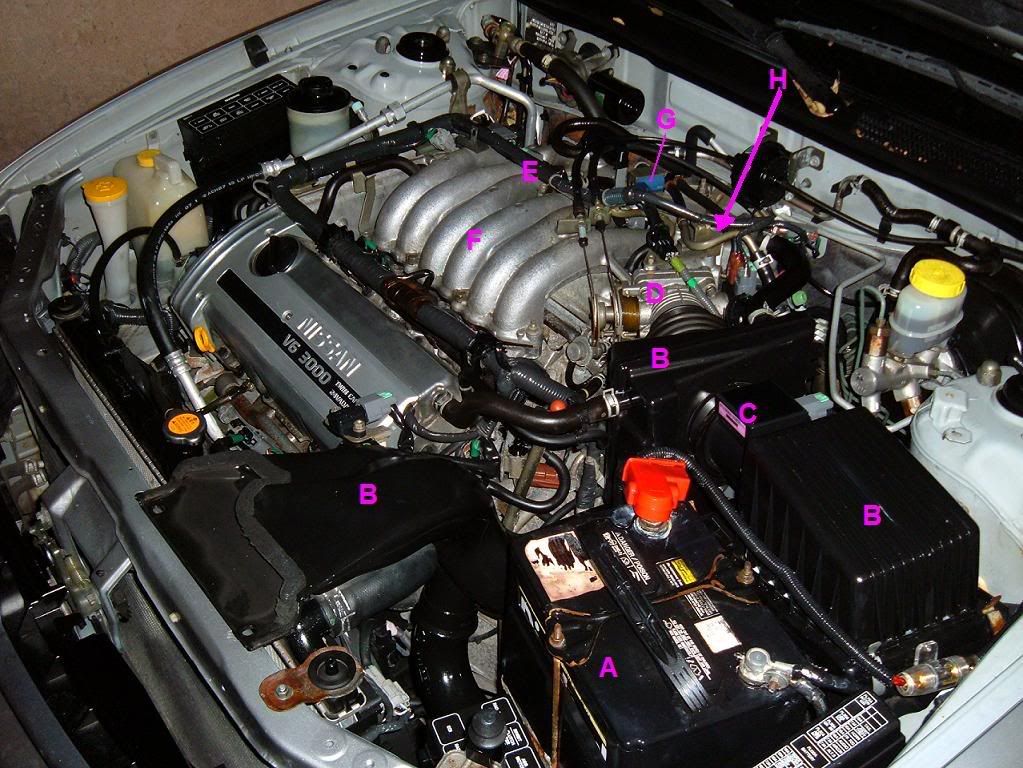
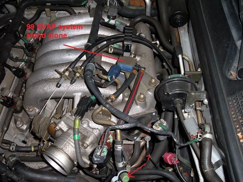
(ignore the "stand alone" label)
Here is your EGR tube removal since you need to use the 5th gen EGR tube with the 5th gen Upper Intake Manifold. I used a Dremel and a cutting wheel to cut the stud tip off. This is necessary to remove the nut holding the EGR tube itself, since that brass looking tube is in the way. I've read you can also cut it using a hacksaw blade...without the handle. Might take a while though. Make sure you plug/cover your fuel lines before grinding away here to avoid any unwanted ignitions.

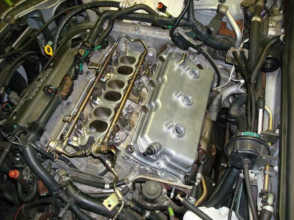
-Rear valve cover and Lower Intake manifold-
Pretty straight forward, unbolt and replace. Use new crush gaskets for the LIM and if your Valve cover gasket is still good, use some Ultra Black RTV. I failed to do so and had a oil leak, had to remove everything, clean the oil off the gasket/valve cover, and RTV the gasket into the valve cover grove, then RTV on the gasket to the head. For the LIM, i took my time torquing the bolts, little by little, starting from the middle, outward. Search for the torquing procedure on the org or in your Factory service manual. Same with Rear valve cover. Also, inspect your new rear valve cover's rubber grommets. There's four, 1- PCV, and 3 for spark plug tubes.
I recommend getting your models Factory service Manual for reference. Search the forum, they're available for download.
If you're attempting the 00vi swap you should be fairly familiar with what needs to be removed and how to remove them. I'll try and go through the basics. Also, before you start, i recommend your protect your fenders with some type of cover between your knees/clothes and the paint. I used some brown wrapping paper and Painters tape to cover both fenders and areas pained near the engine bay. I also recommend you label your hoses and there they go. Use whatever it takes because no matter how good you think your memory is, you WILL lose track of dangling hoses.
A - Battery
B - Air Box
C - Mass Air Flow Sensor MAF (Handle with care...we don't need more problems when troubleshooting your 00vi install)
D - Throttle Body - 4th Gen TB's have a) Throttle Cables, b) Coolant lines (I plugged mine with bolts removed in the process to prevent spilling), c) Connectors (Throttle Position sensors, Brown and Black/Gray) that need to be removed.
E - Electrical log/Harness - This connects to: a) Coil Packs, b) EVAP valve c) EGR temp sensor, d) EGR unit itself, e) Throttle Position sensor. Remove these and the log can be bent out of the way towards passenger side of engine bay.
F - Upper Intake Manifold - Mine had 4 bolts up front towards bumper and 4(?) in the rear attached to mounting brackets. Stick your hand back there and familiarize yourself with the brackets and the number of bolts. Not 100% sure how many there are back there. UIM also has the throttle cables mounted to the bracket, loosen the cables and they slip off the bracket. If your 00vi didnt come with a bracket, avoid removing the cables and just remove the bracket itself and push/tape out of the way. The EVAP valve is also on top of the UIM, remove it and get it out of the way. Your PVC line will also be attached to the UIM, remove the vacuum hose. Behind the UIM, your EGR tube is attached, there are 2 bolts holding it. Under the EGR tube are 2 short coolant lines that run through the UIM. I didnt bother removing mine properly due to the tight space, i just took a knife to the hoses since I replaced the two EGR coolant lines and make a "UIM/Throttle Body coolant bypass". Remember to note which one Runs coolant and which one Returns it, they lead back to the coolant log near the front Valve cover/ Knock sensor connector cable.
G - EVAP valve
H- Not visible in picture but this is where you Idle Air Control Valve is. (IACV)
(ignore the "stand alone" label)
Here is your EGR tube removal since you need to use the 5th gen EGR tube with the 5th gen Upper Intake Manifold. I used a Dremel and a cutting wheel to cut the stud tip off. This is necessary to remove the nut holding the EGR tube itself, since that brass looking tube is in the way. I've read you can also cut it using a hacksaw blade...without the handle. Might take a while though. Make sure you plug/cover your fuel lines before grinding away here to avoid any unwanted ignitions.
-Rear valve cover and Lower Intake manifold-
Pretty straight forward, unbolt and replace. Use new crush gaskets for the LIM and if your Valve cover gasket is still good, use some Ultra Black RTV. I failed to do so and had a oil leak, had to remove everything, clean the oil off the gasket/valve cover, and RTV the gasket into the valve cover grove, then RTV on the gasket to the head. For the LIM, i took my time torquing the bolts, little by little, starting from the middle, outward. Search for the torquing procedure on the org or in your Factory service manual. Same with Rear valve cover. Also, inspect your new rear valve cover's rubber grommets. There's four, 1- PCV, and 3 for spark plug tubes.
Last edited by shadyonedeath; Sep 23, 2009 at 10:55 PM.
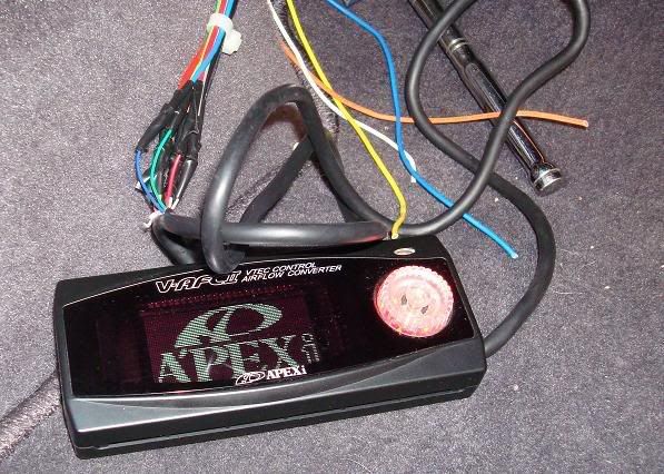
Brief VAFC2 prep and install
Ignore the tags. (VAFC2 Vafc 2 VAFCII VAFC II )
I bought my Apexi VAFC2 used and it was missing the 20 gauge extension harness. The wires on the main unit itself are VERY fine, above 22 gauge, and would not be easy to work with when splicing into the ECU.
What I did was take a old Computer Power supply and use the 20 gauge wires as an extension/adapter for my splice connectors.
Materials:
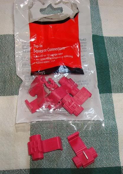
-Splice connectors. Can be found at radio shack.
-Soldering iron / solder
-electrical tape
-Wire stripper
-Wire cutters
-Sacrificial Computer Power Supply Unit wires
-VAFC2 harness (the VAFC2 is inside the glove to protect it... )
)
-wet sponge (cleaning iron tip)
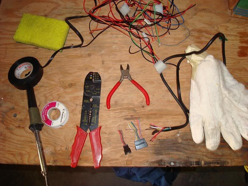
Note: If i could do it again, instead of cutting wires off the Power supply unit, i would have cut off an entire Power supply unit harness with connectors attached and used that as a removable connection to my VAFC2. The PSU clips would have been useful.
I bought my Apexi VAFC2 used and it was missing the 20 gauge extension harness. The wires on the main unit itself are VERY fine, above 22 gauge, and would not be easy to work with when splicing into the ECU.
What I did was take a old Computer Power supply and use the 20 gauge wires as an extension/adapter for my splice connectors.
Materials:
-Splice connectors. Can be found at radio shack.
-Soldering iron / solder
-electrical tape
-Wire stripper
-Wire cutters
-Sacrificial Computer Power Supply Unit wires
-VAFC2 harness (the VAFC2 is inside the glove to protect it...
)-wet sponge (cleaning iron tip)
Note: If i could do it again, instead of cutting wires off the Power supply unit, i would have cut off an entire Power supply unit harness with connectors attached and used that as a removable connection to my VAFC2. The PSU clips would have been useful.
Last edited by shadyonedeath; Aug 3, 2009 at 11:29 PM.
First, i started stripping ends of the PSU wire. If your lucky, you'll find matching colors to your VAFC2 harness. I found all of them except for brown and pink. For brown i used Black, as it is a ground, and Orange for Pink.

To strip the super thin wires from the VAFC2 harness itself, i used a new razor blade and gently twisted it around the wire. I then bent the wire to expose the cut and pulled off the insulation with my finger nails. Use common sense on applying pressure on the blade.

My method of soldering is pretty amateurish but i don't care. As long as you make a solid connection, any method works. I just twisted both ends of the wires and bent the tip back with pliers.
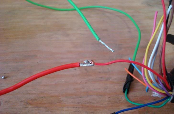
Followed by solder.

I then used electrical tape to seal the connections. Others will suggest heat shrink wrap but i couldn't find any @ Home Depot, radio shack, or auto zone. The result.
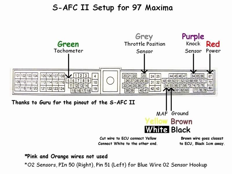
Note: Maxima's DO NOT use VAFC2 wires: ORANGE, LIGHT BLUE, and PURPLE. I covered each tip with electrical tape and then taped them all together and stuffed them back in the main insulation on the VAFC. See diagram in next post for wiring.
To strip the super thin wires from the VAFC2 harness itself, i used a new razor blade and gently twisted it around the wire. I then bent the wire to expose the cut and pulled off the insulation with my finger nails. Use common sense on applying pressure on the blade.
My method of soldering is pretty amateurish but i don't care. As long as you make a solid connection, any method works. I just twisted both ends of the wires and bent the tip back with pliers.
Followed by solder.
I then used electrical tape to seal the connections. Others will suggest heat shrink wrap but i couldn't find any @ Home Depot, radio shack, or auto zone. The result.
Note: Maxima's DO NOT use VAFC2 wires: ORANGE, LIGHT BLUE, and PURPLE. I covered each tip with electrical tape and then taped them all together and stuffed them back in the main insulation on the VAFC. See diagram in next post for wiring.
Last edited by shadyonedeath; Aug 3, 2009 at 12:00 AM.
Before you do ANY of this, make sure you disconnect your Negative battery terminal before you work on splicing into the ECU.
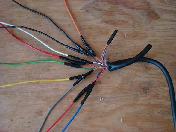
Here we have the wiring. There are two power wires (red) and two ground wires (one black and one brown) required to function the VAFC2. Each set is spliced into the same Power or Ground in on the ECU harness and spaced apart 1cm or more. The MAF wire on the ECU harness must be CUT, not spliced. Once cut, the end still attached to the ECU CONNECTOR/CLIP is connected to the YELLOW wire on the VAFC2 harness. The other end of the MAF wire we cut is attached to the WHITE wire of the VAFC2 harness.
Refer to YOUR Maxima model's Factory Service Manual for correct wire colors on the ECU harness. Wire listings can be found in section EC under ECM Terminals and Reference Value.
Note: I haven't messed with the MAF wire yet because i need to get some plugs for the wiring. These plugs will allow the MAF wire to be reconnected to its original form easily should you choose to remove the VAFC2. Also it helps make a cleaner and secure install. I also avoided splicing into the Knock Sensor wire, apparently this caused some issues with the car starting and previous installers have avoided this part of the install. Please correct me if im wrong on this.
Edit: DO NOT use knock sensor wire. We dont need it. - per gtr_rider. Its not designed for our cars
Go to the Passenger side and remove the cover concealing the rear of the ECU/ECM. You will see a white plastic cover over the wire harness. Use a 10mm socket wrench to remove the bolt and then proceed to remove the harness/clip from the ECU. Once off, give the harness a bit of a tug to expose more working space. Nothing to drastic, just enough to get an extra inch or two. Remove the white/clear plastic cover from the harness clip using a flat head screw driver. Now we can begin searching for our desired wires.

Splice connectors are pretty self explanatory.
Don't ask me how im going to get the plastic cover from the ECU harness back on, i probably wont.
Here we have the wiring. There are two power wires (red) and two ground wires (one black and one brown) required to function the VAFC2. Each set is spliced into the same Power or Ground in on the ECU harness and spaced apart 1cm or more. The MAF wire on the ECU harness must be CUT, not spliced. Once cut, the end still attached to the ECU CONNECTOR/CLIP is connected to the YELLOW wire on the VAFC2 harness. The other end of the MAF wire we cut is attached to the WHITE wire of the VAFC2 harness.
Refer to YOUR Maxima model's Factory Service Manual for correct wire colors on the ECU harness. Wire listings can be found in section EC under ECM Terminals and Reference Value.
Note: I haven't messed with the MAF wire yet because i need to get some plugs for the wiring. These plugs will allow the MAF wire to be reconnected to its original form easily should you choose to remove the VAFC2. Also it helps make a cleaner and secure install. I also avoided splicing into the Knock Sensor wire, apparently this caused some issues with the car starting and previous installers have avoided this part of the install. Please correct me if im wrong on this.
Edit: DO NOT use knock sensor wire. We dont need it. - per gtr_rider. Its not designed for our cars
Go to the Passenger side and remove the cover concealing the rear of the ECU/ECM. You will see a white plastic cover over the wire harness. Use a 10mm socket wrench to remove the bolt and then proceed to remove the harness/clip from the ECU. Once off, give the harness a bit of a tug to expose more working space. Nothing to drastic, just enough to get an extra inch or two. Remove the white/clear plastic cover from the harness clip using a flat head screw driver. Now we can begin searching for our desired wires.
Splice connectors are pretty self explanatory.
Don't ask me how im going to get the plastic cover from the ECU harness back on, i probably wont.
Last edited by shadyonedeath; Sep 9, 2009 at 04:07 PM.
Powering on
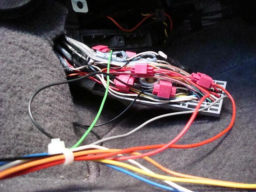
Plug ECU harness back in, bolt it on, and reconnect your negative battery terminal. Turn key to ON position and if all connections are correct, enjoy your working VAFC2. I did it on my first try.
Note: The Yellowand white wire above are for the MAF wire. I didn't get to this yet as i need some plug connectors. The Blue wire i believe is for a Wideband 02 sensor for tuning. Don't have this yet, so also not used. The Orange wire you see is actually routed to the PINK wire on the VAFC2. PINK wire is used to send the 12v signal to the VIAS to activate the 00vi.
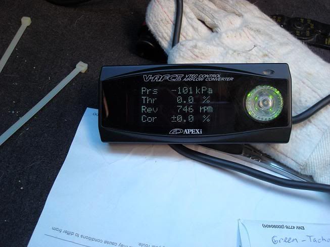
All systems go. At first my RPM signal wasnt working. I went back and made sure the tachmeter connecter was fully spliced using a pair of pliers. It did the trick and everything functions correctly.
Note: The Yellowand white wire above are for the MAF wire. I didn't get to this yet as i need some plug connectors. The Blue wire i believe is for a Wideband 02 sensor for tuning. Don't have this yet, so also not used. The Orange wire you see is actually routed to the PINK wire on the VAFC2. PINK wire is used to send the 12v signal to the VIAS to activate the 00vi.
All systems go. At first my RPM signal wasnt working. I went back and made sure the tachmeter connecter was fully spliced using a pair of pliers. It did the trick and everything functions correctly.
Last edited by shadyonedeath; Aug 3, 2009 at 12:12 AM.


Plug ECU harness back in, bolt it on, and reconnect your negative battery terminal. Turn key to ON position and if all connections are correct, enjoy your working VAFC2. I did it on my first try.
Note: The Yellowand white wire above are for the MAF wire. I didn't get to this yet as i need some plug connectors. The Blue wire i believe is for a Wideband 02 sensor for tuning. Don't have this yet, so also not used. The Orange wire you see is actually routed to the PINK wire on the VAFC2. PINK wire is used to send the 12v signal to the VIAS to activate the 00vi.
All systems go. At first my RPM signal wasnt working. I went back and made sure the tachmeter connecter was fully spliced using a pair of pliers. It did the trick and everything functions correctly.


blue or light blue? Plus I don't think vafc has wideband capability. Light blue is TDC signal and blue is VTM ("VTM is the signal from the engine components saying it's ok to hit vtec, it makes sure operating temp is correct, oil pressure is high enough, etc. When all the requirements are met it sends the "ok" signal through the VTM to engage VTEC.")
Last edited by shadyonedeath; Aug 15, 2009 at 11:49 AM.
I'm looking at the vafc2 wiring diagram right now and I don't see O2 anywhere. Maybe the online manual from APEXI is different than the one that comes with the unit itself. Can't tell for sure as mine is in japanese...
If you notice, this diagram was for SAFC not VAFC, but regardless, i did not hook up the blue wire. Ill note it on the write up. thanks
^^Updated with 00vi painting
I finally got some more brass fittings from ebay. My local source ran out of them and they were getting a bit pricey. (5$ a elbow). I got (6) 3/8 x 1/4 elbow fittings for about 10$.
Why six? Well, i need two for the 2nd 00vi im going to sell, 2 for my oil catch can, and 1 for my current 00vi, which i painted in above posts.
Last edited by shadyonedeath; Sep 9, 2009 at 04:08 PM.
-5th gen Upper intake manifold
-5th gen Lower intake manifold
-5th gen fuel rail w/Damper and FPR, No adapter.
-5th gen FBJC100 290cc injectors
-5th gen Throttle Body
-5th gen Rear valve cover
-5th gen Rear Coil packs
-5th gen Snorkel & Air box modified to fit 4th gen MAF
-IACV Adapter
-4th gen Idle Air Control Valve
-Apexi VAFC2
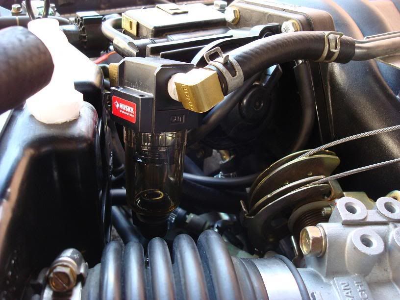
-Husky (Home Depot) Oil Catch Can
-5th gen Lower intake manifold
-5th gen fuel rail w/Damper and FPR, No adapter.
-5th gen FBJC100 290cc injectors
-5th gen Throttle Body
-5th gen Rear valve cover
-5th gen Rear Coil packs
-5th gen Snorkel & Air box modified to fit 4th gen MAF
-IACV Adapter
-4th gen Idle Air Control Valve
-Apexi VAFC2
-Husky (Home Depot) Oil Catch Can
Last edited by shadyonedeath; Sep 16, 2009 at 04:11 PM.


Thanks for updating the thread. Just in time for me and my '99 SE auto. I've got my 00VI with all 5th gen components waiting to be installed. I just wired up my vafc2 last night and the only issue I had was with the ground pin #55. It was black and not white. (Anyone interested in pics, check my album)
I've got my 00VI with all 5th gen components waiting to be installed. I just wired up my vafc2 last night and the only issue I had was with the ground pin #55. It was black and not white. (Anyone interested in pics, check my album)

THIS WRITEUP IS AMAZING! Currently planning on doing it myself have some down time where I cannot drive! This will be a great addition to my collection of notes, writeups, and information lol


Good write up.
About those barb fittings that you drill and tap into the manifold. I use these fittings used on construction & farm equipment, they are high pressure rated but that does not matter much. What is cool is they have a thread along with a swivel nut and gasket. This is so you can point the barb in the direction you want it to go while holding it with locking pliers. Then with your other hand use an open wrench to torque the swivel nut and install the fitting to the manifold.
The two downsides with these fittings is that they are expensive, like 10 dollars each; I am trying to find a cheaper lower pressure alternative. Second they are rated for 1000 PSI so they have very thick walls, I have to drill the walls out to 3/8" so the EVAP and remote IACV work without CELs.
I've installed a couple of VIs and have used these fittings for the last two installs I've done. One of them is running S/C at 14 PSI very well, so I guess the fittings and VI work I did are holding up well.


Plug ECU harness back in, bolt it on, and reconnect your negative battery terminal. Turn key to ON position and if all connections are correct, enjoy your working VAFC2. I did it on my first try.
Note: The Yellowand white wire above are for the MAF wire. I didn't get to this yet as i need some plug connectors. The Blue wire i believe is for a Wideband 02 sensor for tuning. Don't have this yet, so also not used. The Orange wire you see is actually routed to the PINK wire on the VAFC2. PINK wire is used to send the 12v signal to the VIAS to activate the 00vi.
All systems go. At first my RPM signal wasnt working. I went back and made sure the tachmeter connecter was fully spliced using a pair of pliers. It did the trick and everything functions correctly.
Note: The Yellowand white wire above are for the MAF wire. I didn't get to this yet as i need some plug connectors. The Blue wire i believe is for a Wideband 02 sensor for tuning. Don't have this yet, so also not used. The Orange wire you see is actually routed to the PINK wire on the VAFC2. PINK wire is used to send the 12v signal to the VIAS to activate the 00vi.
All systems go. At first my RPM signal wasnt working. I went back and made sure the tachmeter connecter was fully spliced using a pair of pliers. It did the trick and everything functions correctly.
I found diagrams for the 5.5 gen but none for the 3.0.
Is it the same as the fourth gen for a vafc 2?

Newbie - Just Registered
Joined: Aug 2011
Posts: 14
From: Duluth,GA
honestly lol wats the 00vi do to the 4th gen motor? some sort of lift. sorry bout the noob Q?im trying to pack a little more power.Ive got warpspeed y pipe,headers,short raM...its auto but its my DD.just trynna have a kick
Also there is a website called vqpower, look it up. Can be found there too.


