
Trunk re-build ... Third times a charm

Thread Starter

Joined: Oct 2002
Posts: 1,199
From: Ontario, Canada
Trunk re-build ... Third times a charm
Well it has been about a year since I last had my trunk torn apart.
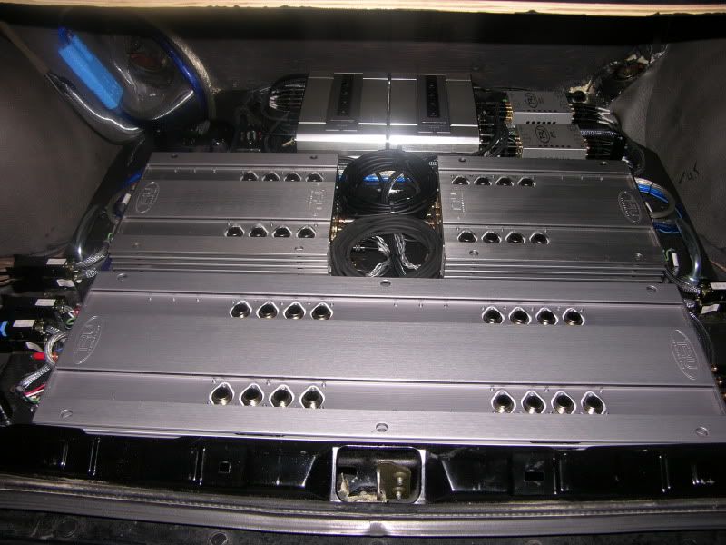
Here is a shot from May 09.
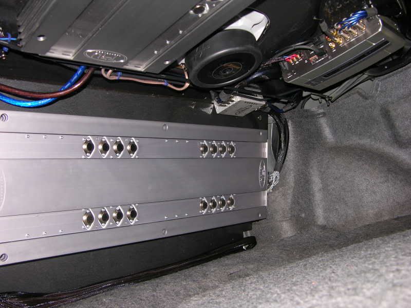
I have since aquired another processor and a second B-475. Since there is no additional room on the underside of the rear deck, I am moving everything to the floor.
I am about 50% of the way complete so I will post pics of what I have done so far and will add more as things progress.
Here is a shot from May 09.
I have since aquired another processor and a second B-475. Since there is no additional room on the underside of the rear deck, I am moving everything to the floor.
I am about 50% of the way complete so I will post pics of what I have done so far and will add more as things progress.
Thread Starter
Joined: Oct 2002
Posts: 1,199
From: Ontario, Canada
The first order of business after removing everything from the trunk was to create some mounting points for my amplifier/processor board.
I wanted the board to be easily removable in case I ever needed to access the spare tire underneath.
I decided to create four solid mounts that would be screwed right into the trunk floor with threaded inserts for bolting the amp board to.
I started by cutting a sheet of 3/4 fir plywood to the size that would fit nicely in the trunk. I placed blocks of varying heights under it until I got it to sit flat. I then picked four locations for the fasteners to go that would not interfere with any of the components. The four spots were then transferred through to the floor of the trunk. Four 1/4 threaded inserts were then glued to dowels of varying heights which were in turn glued to the floor of the trunk. I then popped in four screws around the circumference of each insert to increase the hold each mount would have on the trunk floor.
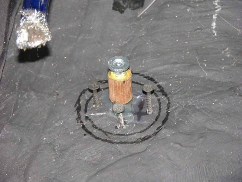
Next was to form a cylindrical mold around each mounting point and then fill it with epoxy
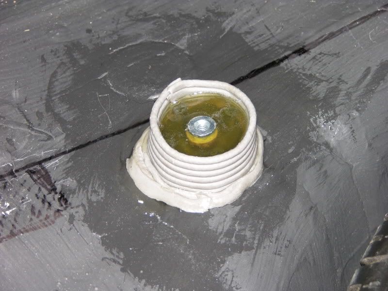
Here is a shot of all four complete. I glued a "soft" 2" rubber washer to the top of each one. These serve as a compressible coupling that will allow the connector bolts to be preloaded somewhat so they will not vibrate loose. (same idea as a split lockwasher)
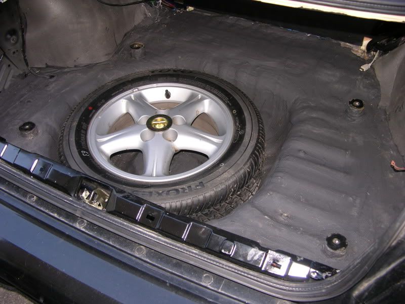
I wanted the board to be easily removable in case I ever needed to access the spare tire underneath.
I decided to create four solid mounts that would be screwed right into the trunk floor with threaded inserts for bolting the amp board to.
I started by cutting a sheet of 3/4 fir plywood to the size that would fit nicely in the trunk. I placed blocks of varying heights under it until I got it to sit flat. I then picked four locations for the fasteners to go that would not interfere with any of the components. The four spots were then transferred through to the floor of the trunk. Four 1/4 threaded inserts were then glued to dowels of varying heights which were in turn glued to the floor of the trunk. I then popped in four screws around the circumference of each insert to increase the hold each mount would have on the trunk floor.
Next was to form a cylindrical mold around each mounting point and then fill it with epoxy
Here is a shot of all four complete. I glued a "soft" 2" rubber washer to the top of each one. These serve as a compressible coupling that will allow the connector bolts to be preloaded somewhat so they will not vibrate loose. (same idea as a split lockwasher)
Last edited by eng92; May 16, 2010 at 08:44 PM.
Thread Starter
Joined: Oct 2002
Posts: 1,199
From: Ontario, Canada
Next up was creating the board for mounting everything.
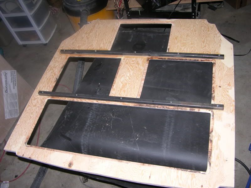
Here is the sheet of 3/4 fir ply cut to size. Just the board alone weighed in at 22 lbs. If I am going to be able to pull this board out of the trunk with 3 amps and 2 processors attached, it is going to have to go on a diet. I essentially wanted to remove as much material as possible under the components themselves but leave plenty of meat around all the mounting bolt locations. The pattern marked out on the board is what I came up with.
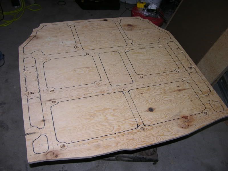
Armed with a brand new Freud 1" mortising bit, I hogged 7 lbs of wood out of the board. That is one hell of a lot of sawdust. I wish I would have taken a picture of the garage when I was done.
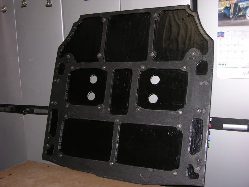
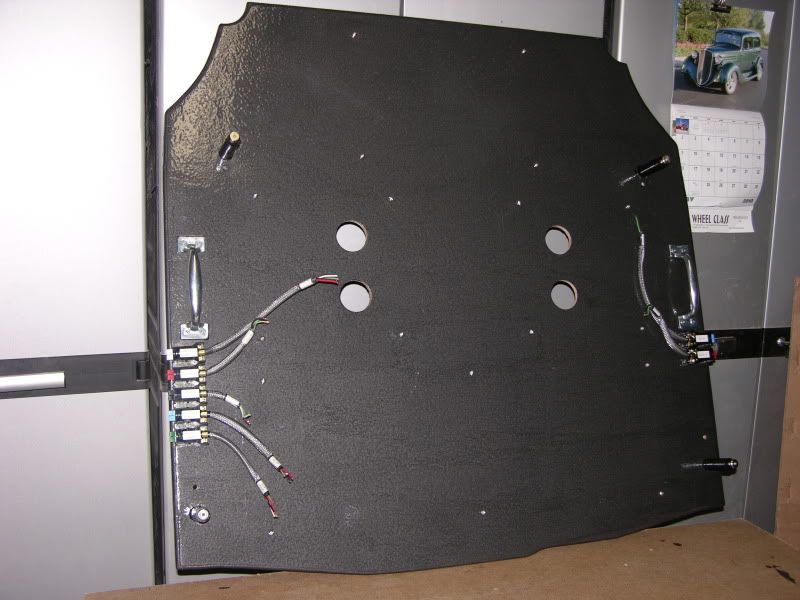
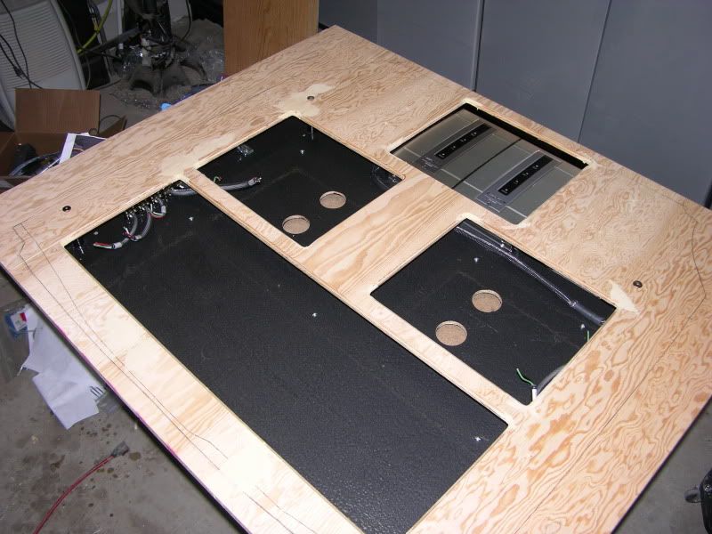
Below is a picture of the back of the amp mounting board in its current state. I painted it up so moisture would not cause any problems. The four large holes are for the cooling fans in the two B-475 amps. There are also 30 t-nuts countersunk and glued into the bottom of the board for bolting the amps and processors in place
Here is the sheet of 3/4 fir ply cut to size. Just the board alone weighed in at 22 lbs. If I am going to be able to pull this board out of the trunk with 3 amps and 2 processors attached, it is going to have to go on a diet. I essentially wanted to remove as much material as possible under the components themselves but leave plenty of meat around all the mounting bolt locations. The pattern marked out on the board is what I came up with.
Armed with a brand new Freud 1" mortising bit, I hogged 7 lbs of wood out of the board. That is one hell of a lot of sawdust. I wish I would have taken a picture of the garage when I was done.
Below is a picture of the back of the amp mounting board in its current state. I painted it up so moisture would not cause any problems. The four large holes are for the cooling fans in the two B-475 amps. There are also 30 t-nuts countersunk and glued into the bottom of the board for bolting the amps and processors in place
Last edited by eng92; May 16, 2010 at 09:02 PM.
Thread Starter
Joined: Oct 2002
Posts: 1,199
From: Ontario, Canada
Well that is the boring stuff out of the way.
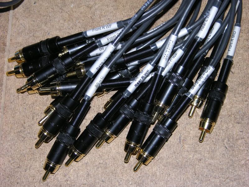
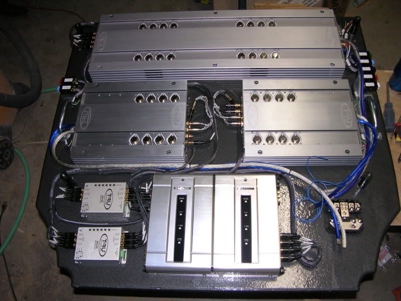
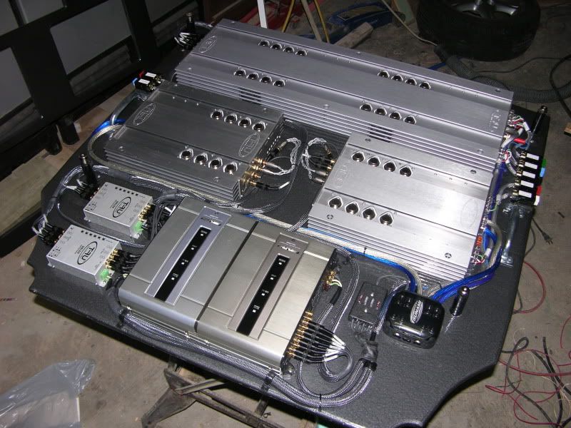
Here is a shot of the components that will be going on the board. I am making up my own interconnects so I am just laying out the cables for length
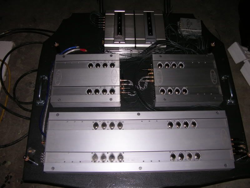
I can almost hear Don now "A new B8 would look much better than those two "old" B-4-75s"
A second line driver will be going up on the top right.
Power distribution will be in the top left
The handles are for lifting the board in and out of the trunk. They will not be visible through the cover.
Here is a shot of the RCAs in progress. (22 cables to make)
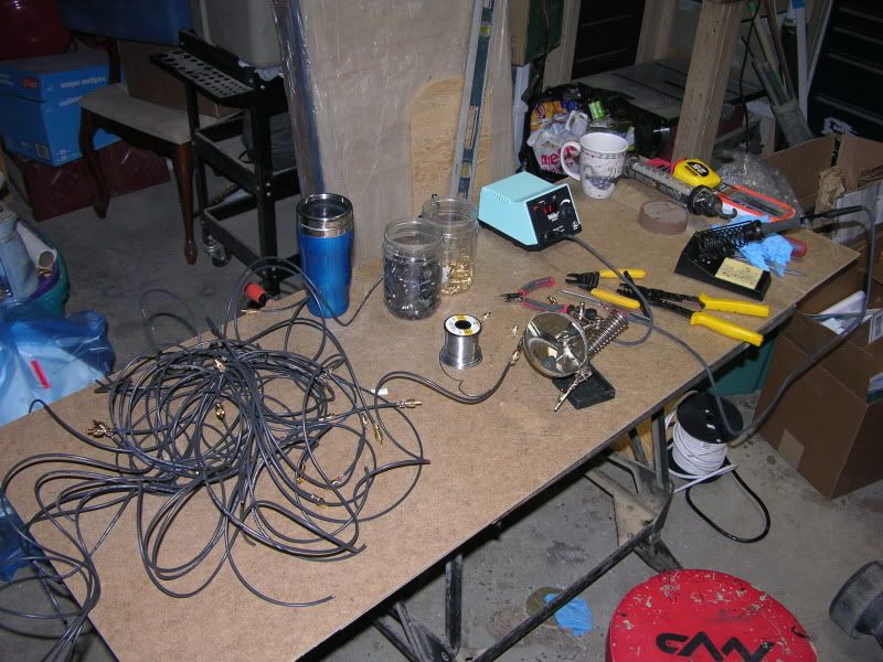
Halfway done. Now I have to put the connectors on the other end
Here is a shot of the components that will be going on the board. I am making up my own interconnects so I am just laying out the cables for length
I can almost hear Don now "A new B8 would look much better than those two "old" B-4-75s"
A second line driver will be going up on the top right.
Power distribution will be in the top left
The handles are for lifting the board in and out of the trunk. They will not be visible through the cover.
Here is a shot of the RCAs in progress. (22 cables to make)
Halfway done. Now I have to put the connectors on the other end
Last edited by eng92; May 16, 2010 at 09:52 PM.
Thread Starter
Joined: Oct 2002
Posts: 1,199
From: Ontario, Canada
While cruising the Allied Electronics site I came across these connectors that will do a fine job of allowing me to quickly disconnect all the speakers if I need to.
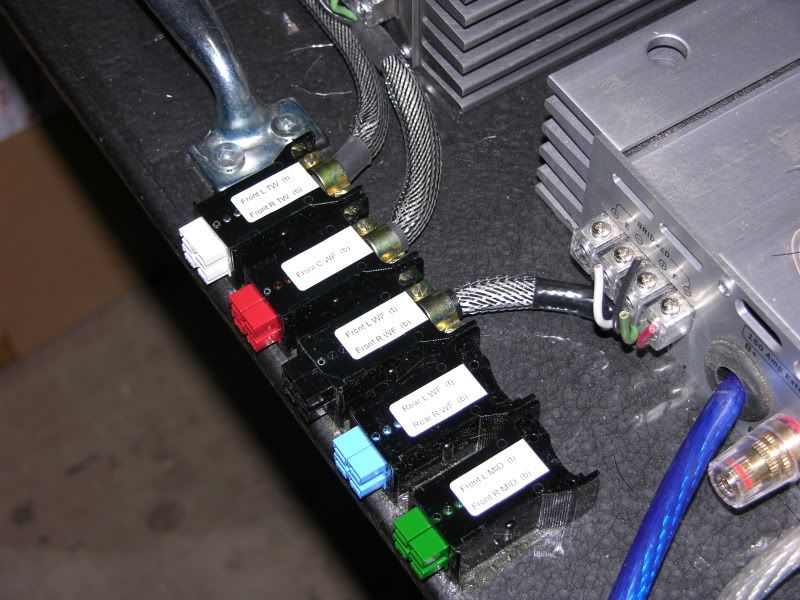
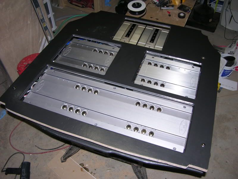
Here is a shot of the top of the board with all the speaker connectors and cables attached. The four black posts are the mounting standoffs for the cover.
I am expecting a few packages to arrive this week so I should have some more updates this weekend.
Here is a shot of the top of the board with all the speaker connectors and cables attached. The four black posts are the mounting standoffs for the cover.
I am expecting a few packages to arrive this week so I should have some more updates this weekend.
Last edited by eng92; May 16, 2010 at 09:50 PM.


Thread Starter
Joined: Oct 2002
Posts: 1,199
From: Ontario, Canada
You have a different attitude though when you are not a professional installer and just doing it for yourself.
I look at it as a hobby that I enjoy. I do not watch tv or play video games. Going out to the garage, cranking the tunes, and a fresh pot of coffee are just what I need to relax at the end of a typical day.
Thread Starter
Joined: Oct 2002
Posts: 1,199
From: Ontario, Canada
A little trinket (line driver) arrived in the mail from NJ today (Thanks Don  )
)
I was able to finish making my interconnects and start wiring the board
I also started making the board that will cover all of the components
Only the three amps and processors will be visible. The openings will be covered with a clear, scratch resistant polycarbonate.
)I was able to finish making my interconnects and start wiring the board
I also started making the board that will cover all of the components
Only the three amps and processors will be visible. The openings will be covered with a clear, scratch resistant polycarbonate.


Thread Starter
Joined: Oct 2002
Posts: 1,199
From: Ontario, Canada
Thank you for all the kind words guys.
This has not been a very productive week as far as this build goes. First, Allied sent me a few wrong components I needed for a fan circuit and then I received a distribution block that was not quite as advertised.
I purchased this combination positive/ground distribution block
http://www.autotoys.com/x/product.php?productid=15744 because it was perfect for this build.
When it arrived, I noticed immediately that all the outputs were 8ga and not 4ga as advertised. That is a piece of 4ga. in the photo.
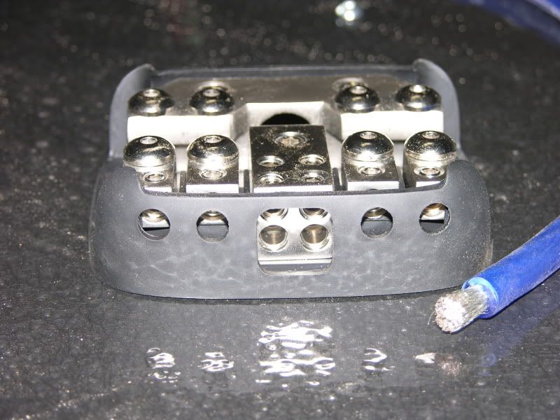
The seller offered me a refund or an exchange on something that would work. I could not find any block that did positive/ground with 1/0 ga in and (4) 4 ga out.
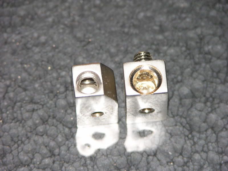
After a couple of quick measurements, I figured I could just drill this one out to accept the larger wire.
These two holes were the same size before I started. There was just enough room to counter bore for the cable jacket recess without breaking through the side.
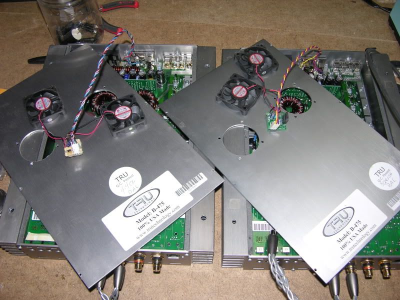
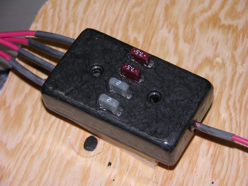
One of my two B-475 amps came with a set of factory retrofit fans. I purchased a pair of identical fans ($7 on Fleabay) and about $6 worth of electrical components from Allied to duplicate the fan turn-on circuit.
My board (left) isn't nearly as professional looking as the one from Tru but it works
This is a long weekend up here for us Canadians so I have high hopes of making some decent progess on this
This has not been a very productive week as far as this build goes. First, Allied sent me a few wrong components I needed for a fan circuit and then I received a distribution block that was not quite as advertised.
I purchased this combination positive/ground distribution block
http://www.autotoys.com/x/product.php?productid=15744 because it was perfect for this build.
When it arrived, I noticed immediately that all the outputs were 8ga and not 4ga as advertised. That is a piece of 4ga. in the photo.
The seller offered me a refund or an exchange on something that would work. I could not find any block that did positive/ground with 1/0 ga in and (4) 4 ga out.
After a couple of quick measurements, I figured I could just drill this one out to accept the larger wire.
These two holes were the same size before I started. There was just enough room to counter bore for the cable jacket recess without breaking through the side.
One of my two B-475 amps came with a set of factory retrofit fans. I purchased a pair of identical fans ($7 on Fleabay) and about $6 worth of electrical components from Allied to duplicate the fan turn-on circuit.
My board (left) isn't nearly as professional looking as the one from Tru but it works
This is a long weekend up here for us Canadians so I have high hopes of making some decent progess on this
Last edited by eng92; May 22, 2010 at 09:53 AM.

Thread Starter
Joined: Oct 2002
Posts: 1,199
From: Ontario, Canada
I will be using all 8 front channels (3-way L+R and 2-way centre)
I am only using 3 channels for the rear (L + R + sub) The rears will be 2-way passives.
Thread Starter
Joined: Oct 2002
Posts: 1,199
From: Ontario, Canada
I made some more progress on the wiring tonight. I just need to wire up the pos/rem/gnd on the line drivers/processors and wire up the power/ground distribution block
I also finished cutting the profile for the cover and sprayed a coat of primer on it.
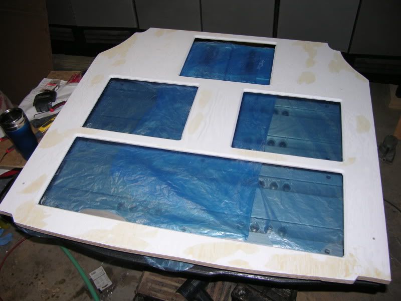
I also finished cutting the profile for the cover and sprayed a coat of primer on it.
Last edited by eng92; May 23, 2010 at 09:25 PM.
Nice work, nice stuff. Makes me wish I had a real job.
I'm exactly the same way. I love garage projects!
I'm exactly the same way. I love garage projects!
Thread Starter
Joined: Oct 2002
Posts: 1,199
From: Ontario, Canada
Only minor progress made so far this week.
I made up a mini fuse holder with four circuits to cover the two line drivers and processors.
Starting with four inline fuse holders and a chunk of maple.
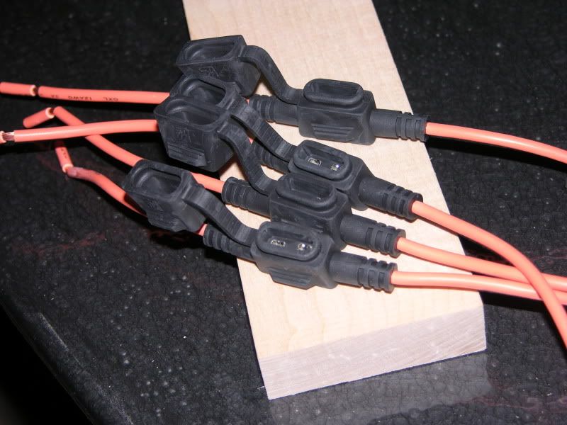
After a few hours, the end result is:
 .
.
I sprayed a couple of light coats of top coat onto the cover board and I was not impressed with the color.
It is the same brand, type and color as the paint I used for the amp board except it is a spray instead of a brush-on. The finishes are not even close to a match.
The problem with the brush-on paint is I find it way too soft even after curing for several weeks. It is not suitable for use as a finish on a trunk floor.
I am going to have to look at some other "tough" paints to see if I can find a color that I like.
I also threw the fully loaded amp board onto the scales (82.5 lbs !!!!) It is quite the weight to hold with outstretched arms. It does wonders for the lower back as well.
I made up a mini fuse holder with four circuits to cover the two line drivers and processors.
Starting with four inline fuse holders and a chunk of maple.
After a few hours, the end result is:
.I sprayed a couple of light coats of top coat onto the cover board and I was not impressed with the color.
It is the same brand, type and color as the paint I used for the amp board except it is a spray instead of a brush-on. The finishes are not even close to a match.
The problem with the brush-on paint is I find it way too soft even after curing for several weeks. It is not suitable for use as a finish on a trunk floor.
I am going to have to look at some other "tough" paints to see if I can find a color that I like.
I also threw the fully loaded amp board onto the scales (82.5 lbs
!!!!) It is quite the weight to hold with outstretched arms. It does wonders for the lower back as well.
Thread Starter
Joined: Oct 2002
Posts: 1,199
From: Ontario, Canada
The wiring is finally almost finished
Here is a shot of the new fuse block all wired in along with the rest of the power/ground connections.
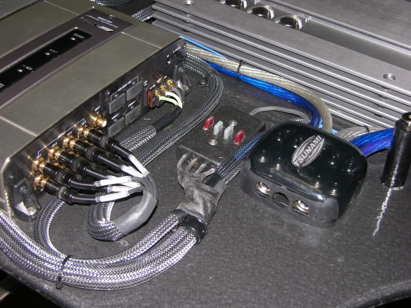
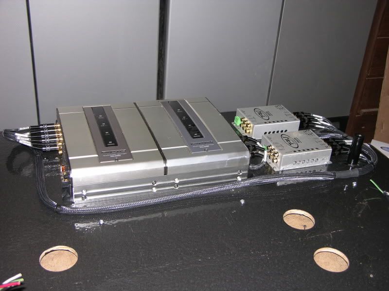
And a shot of the entire board
I still need to connect the two processors together with Ionbus and DVD Audio cables. I do not know why Alpine did not place pass through connectors on the backside of the processors. They provided tiebars to mechanically connect them together but did nothing on the electrical side.
Both cables are 18' long. I am tempted to buy a couple of spares and try and shorten them to about 2' long.
Anyways, next up is setting up the power/ground and pulling a few more sets of speaker cables in the car. I want to have this board in the car by the end of the weekend.
Here is a shot of the new fuse block all wired in along with the rest of the power/ground connections.
And a shot of the entire board
I still need to connect the two processors together with Ionbus and DVD Audio cables. I do not know why Alpine did not place pass through connectors on the backside of the processors. They provided tiebars to mechanically connect them together but did nothing on the electrical side.
Both cables are 18' long. I am tempted to buy a couple of spares and try and shorten them to about 2' long.
Anyways, next up is setting up the power/ground and pulling a few more sets of speaker cables in the car. I want to have this board in the car by the end of the weekend.

Thread Starter
Joined: Oct 2002
Posts: 1,199
From: Ontario, Canada
I put power to it tonight on the bench just to make sure everything was working.
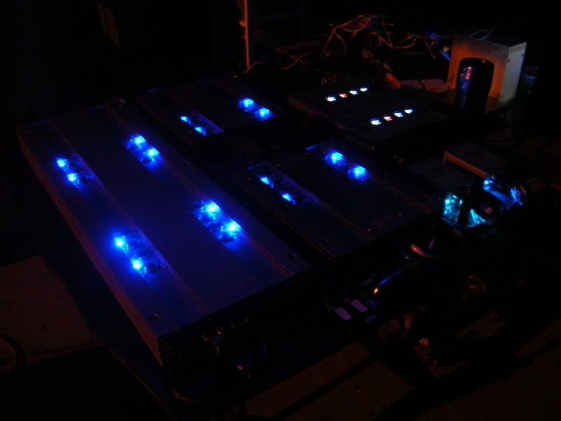
I hooked up a small speaker to each of the 11 amp channels I am using and everything is good to go.
I hooked up a small speaker to each of the 11 amp channels I am using and everything is good to go.
Thread Starter
Joined: Oct 2002
Posts: 1,199
From: Ontario, Canada
Only minimal progress was made today.
I added a solid ground to the trunk floor. The area between the suspension towers is one of the thickest parts of the chassis in the rear of the vehicle.
I had to dig through several layers of deadening to finally get to the metal.
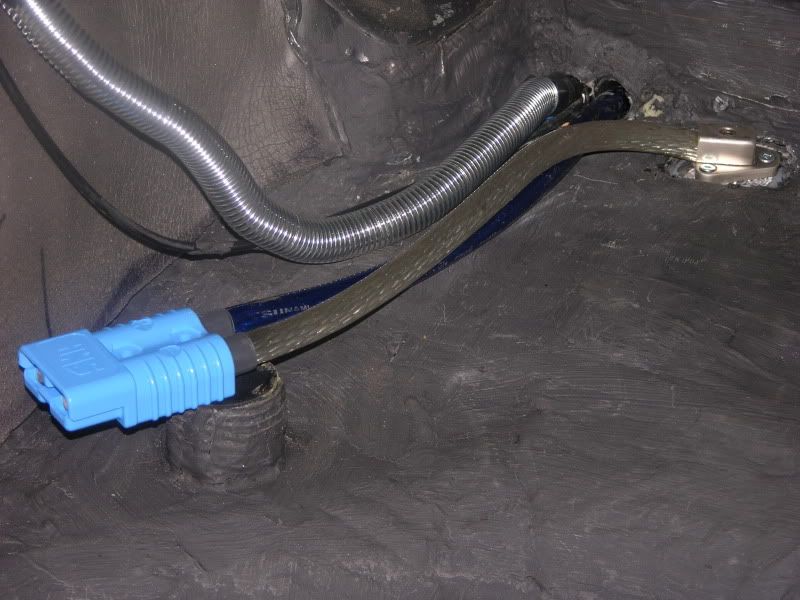
I am using a heavy duty quick disconnect to run the power to my amp board. It is the same type of connector used for the battery connections on electric forklifts and other high current mobile DC applications.
I added a solid ground to the trunk floor. The area between the suspension towers is one of the thickest parts of the chassis in the rear of the vehicle.
I had to dig through several layers of deadening to finally get to the metal.
I am using a heavy duty quick disconnect to run the power to my amp board. It is the same type of connector used for the battery connections on electric forklifts and other high current mobile DC applications.


Thread Starter
Joined: Oct 2002
Posts: 1,199
From: Ontario, Canada
I installed the amp board in the trunk tonight.
It went in a lot easier than I thought it would. The handles were right at the balance point so the 82lbs weight was not a problem to keep under control.
The speaker and power cables are all hooked up. Next up is finishing off the cover.
It went in a lot easier than I thought it would. The handles were right at the balance point so the 82lbs weight was not a problem to keep under control.
The speaker and power cables are all hooked up. Next up is finishing off the cover.
Thread Starter
Joined: Oct 2002
Posts: 1,199
From: Ontario, Canada
Thank you for the kind words. Things are progressing slowly but surely.
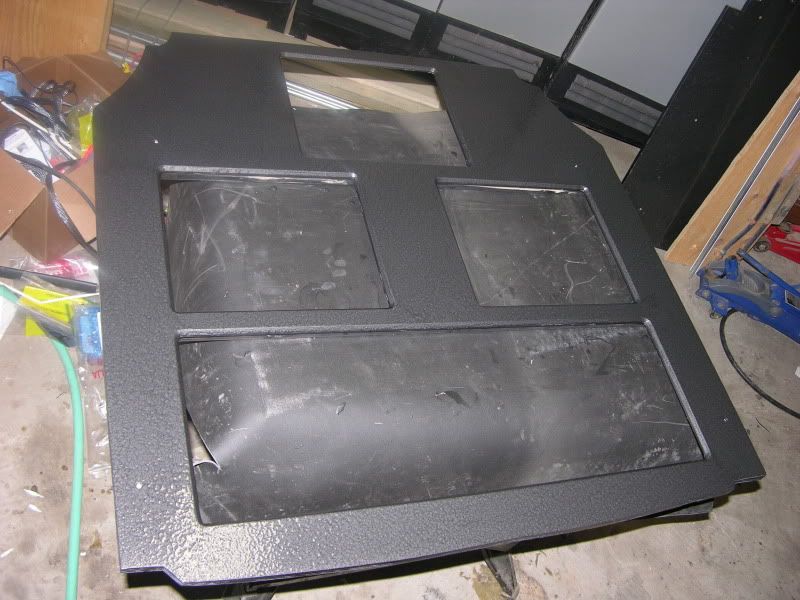
I accomplished a couple of things on the cover tonight.
First off was gluing and screwing a couple of pieces of 3/4" sq. tube to the bottom of the board to stiffen it up. This is effectively going to be the "floor" of my trunk and I don't want those thin strips of wood to fail if I throw a couple of hundred pounds of building materials on top.
While the glue was drying, I flipped the board over and painted the top side with a grey/black hammertone finish. I am going to let it cure for about a week and then I am going to apply a couple of coats of clear polyurethane floor finish.
Last edited by eng92; Jun 3, 2010 at 09:25 PM.
Still loving it Dave. My only question is ... where do you purchase the free time from ? I have been trying, but I can't seem to find anyone selling more hours to the day lately. 
Thread Starter
Joined: Oct 2002
Posts: 1,199
From: Ontario, Canada
Thanks Don,
I have designated 11pm - 6am daily as "me" time. (ie. kids in bed, wifey at work.) I usually take 2 hours of that to work on my projects and the balance for sleeping.
I have designated 11pm - 6am daily as "me" time. (ie. kids in bed, wifey at work.) I usually take 2 hours of that to work on my projects and the balance for sleeping.


