
Wideband cable routing


Wideband cable routing
I just bought an Innovate LC-1 and I am looking to install it. I want the cabling hidden the best that it can be. I've been looking around the engine bay and under the car and see three points of entry. There is the grommet for the engine control harness that runs through the firewall directly behind the engine. This location is just a bout impossible to access. There is the grommet that the rear O2 sensor cable goes through, but it looks like i'd have to cut it to make the ends of the LC-1 fit through. Seeing as this is on the underside of the car, I'd rather not compromise it's ability to seal out water. I am also worried about puting the wideband controller in a position where there is a chance it could come between the ground the and car as it bottoms out.The third location I can find is the power harness, which runs behind the driver's side fender. This would require taking the dender off to access, but it might be the best location. What do you think. Where did you run the cabling for your wideband?

Just use the Gromet behind the pass seat, where the other O2 plugs in. If the Stock O2 is okay there, so will yours. Run the plug through where the gromet goes, than try to seal it back up with something like weather strip sealant.

The connectors in question are 1/8 stereo jacks that are molded into the cable itself. If anything, I'd cut them off, feed the wire through, and solder them back on - I'm cool like that.
Electronics Guru
97 Maxima
If you plan on retaining that title, id suggest you get to it!

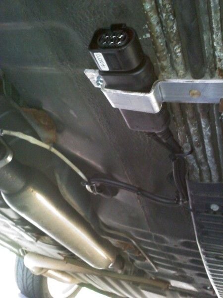
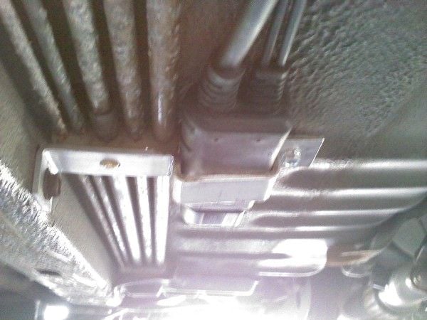
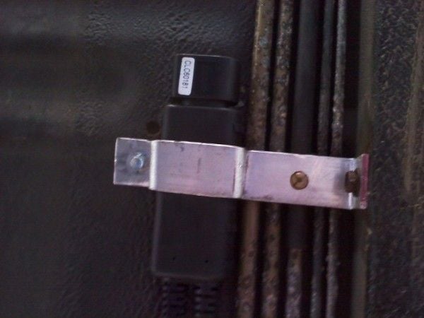
Some pics of the install. Once the connectors were cut off the smaller cables, I lubricated all of the cables and was able to easily pass them through the grommet for the rear O2 sensor. A new bracket was made to mount the controller. This ensures that it will never fall below the level of the unibody rail and thus never hit the ground. It is mounted where one of the brackets that held up the gas and brake lines used to be.
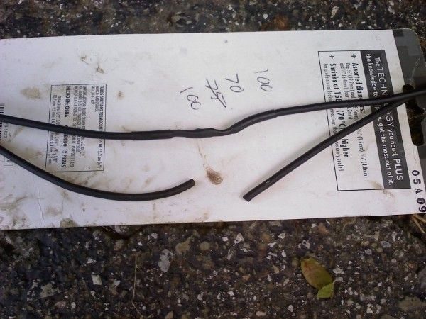
After the cables were passed through the grommet, they had to be spliced with their respective ends. Because there were two cables that would have been identical after the connectors were removed, I did them one at a time to avoid mixing them up. Here is a picture of the two cables. The one cable has been spliced, and the other is about to be.
After the cables were passed through the grommet, they had to be spliced with their respective ends. Because there were two cables that would have been identical after the connectors were removed, I did them one at a time to avoid mixing them up. Here is a picture of the two cables. The one cable has been spliced, and the other is about to be.

Thread
Thread Starter
Forum
Replies
Last Post
CAN-Toronto FS: E-Manage Ultimate and patch cable
knight_yyz
5th Generation Classifieds (2000-2003)
3
Oct 24, 2015 08:05 AM
pktaske
6th Generation Maxima (2004-2008)
0
Sep 4, 2015 08:40 AM