
The acceleration/shifting problem


then what does VE-type TPS mean?
I'm using the injectors that came with the JDM, I don't know if mechanic replaced temp sensor or use my old one, everything else I have no idea and I don't even know location or how do they look like (oil pressure sensor, fuel pressure regulator, power transistor)
Could you guide me to check those with pictures? and how do I know if they are from the JDM or USDM? honestly the parts I have from JDM and USDM looks identical! I know there may be some differences on specs of every sensor I just mention that they look identical.

Senior Member
Joined: Dec 2004
Posts: 4,323
From: EU Scandinavia
TPS: VGE 1kOhm-9kOhms, VE 0.5k-5kOhm. JDM and USDM not relevant here.
Oil pressure switch is a switch is a switch, forget it. JDM and USDM not relevant here.
Temp sensor ohm ratings can be verified. DO VERIFY. JDM and USDM not relevant here. Neither they can they affect your engine like in the video.


.
.
.
.
.
Sit down and take a deep breath. Write down a plan what to do. Do all systemically, keep log what have been done.
Verify all relevant engine sensors that they do work. TPS, MAF, distr rev sensor, O2. (all others are secondary - e.g. wont 'kill' low rpm like in your video). Then figure out your ECU and TCU versions.
Last edited by Wiking; Apr 11, 2008 at 12:24 PM.
Nope. Only some sensors differ.
TPS: VGE 1kOhm-9kOhms, VE 0.5k-5kOhm. JDM and USDM not relevant here.
Oil pressure switch is a switch is a switch, forget it. JDM and USDM not relevant here.
Temp sensor ohm ratings can be verified. DO VERIFY. JDM and USDM not relevant here. Neither they can they affect your engine like in the video.
.
.
.
.
.
Sit down and take a deep breath. Write down a plan what to do. Do all systemically, keep log what have been done.
Verify all relevant engine sensors that they do work. TPS, MAF, distr rev sensor, O2. (all others are secondary - e.g. wont 'kill' low rpm like in your video). Then figure out your ECU and TCU versions.
waaaait.. the egr temp sensor is on the other side of the engine! it's just below the intake plenum's overhang, just above the green and orange solenoids for powervalve/egr. on your pic above it should be CTS on the left (rear-facing... where you wrote "EGRC") and CHTS aka temp needle sensor on the right (front-facing where you wrote "Engine Temp")

I know that sensor because it cause problems with my old engine preventing my fans to turn on, so that's the coolant temp sensor right? CTS?
BTW I forgot to ask if the MAF measurements should be done on any specific gear, I did all the measures on P, was that ok? or doesn't matter?
X2
I know that sensor because it cause problems with my old engine preventing my fans to turn on, so that's the coolant temp sensor right? CTS?
BTW I forgot to ask if the MAF measurements should be done on any specific gear, I did all the measures on P, was that ok? or doesn't matter?
I know that sensor because it cause problems with my old engine preventing my fans to turn on, so that's the coolant temp sensor right? CTS?
BTW I forgot to ask if the MAF measurements should be done on any specific gear, I did all the measures on P, was that ok? or doesn't matter?
Senior Member
Joined: Dec 2004
Posts: 4,323
From: EU Scandinavia


the other end solenoids:

If theres smtg to correct, pls show me with the source. Pls check
http://www.cardomain.com/ride/748507/3
Not in my max. Just two sensors, like in the schema:
the other end solenoids:
If theres smtg to correct, pls show me with the source. Pls check
http://www.cardomain.com/ride/748507/3
the other end solenoids:
If theres smtg to correct, pls show me with the source. Pls check
http://www.cardomain.com/ride/748507/3
Wiking, you don't have a USDM maxima. you have a euro model and it is safe to ASSuME that there is differences between yours and ours, just like there are differences between the JDM and USDM cars.
well unless the EDM's EGR hose runs on the front side of the engine then there's no way for the EGR temp sensor to be so far away from the EGR system anyhow... but i know what you mean about that. Just look at his car's taillights..
yeah maybe not. i'd think he would, since euro emissions are tighter than US emissions, but maybe EGR is a cheap way of getting "decent" emissions where the EDM has a more expensive, more effective alternative to it? Who knows...
What particular emission(s) do(es) the EGR system help reduce anyhow?
What particular emission(s) do(es) the EGR system help reduce anyhow?
Senior Member
Joined: Dec 2004
Posts: 4,323
From: EU Scandinavia
For what is the schema in the -94 FSM? I guess its for all those minus none = confuzean.
As seen above, there are two temp sensors in the schema, both directly wired to ECU. I have always though that this is bingo with the two water temp sensors in schema/pics above... Maybe not?
New mystery for me: I just found a text in FSM: "...the EGR temp sensor monitors exhaust... EF&EC17" ---> I have not found such temp sensor.
Also there is no (EGRC)-BPT valve - I guess that is common for all VGE's???. FSM page EF&EC15.
Still EGR valve control is affected by coolant temp.
(Note: My rear add on brake light is from local shop, tuned flat ... illegal location - illegal like 'any' safety mods here)
the 94 FSM online is for USDM models.
Canadian models vary slightly on some things, that are covered in the FSM.
African models have differences, it is logical to assume that euro models have variations as well.
Canadian models vary slightly on some things, that are covered in the FSM.
African models have differences, it is logical to assume that euro models have variations as well.
For what is the schema in the -94 FSM? I guess its for all those minus none = confuzean.
As seen above, there are two temp sensors in the schema, both directly wired to ECU. I have always though that this is bingo with the two water temp sensors in schema/pics above... Maybe not?
New mystery for me: I just found a text in FSM: "...the EGR temp sensor monitors exhaust... EF&EC17" ---> I have not found such temp sensor.
Also there is no (EGRC)-BPT valve - I guess that is common for all VGE's???. FSM page EF&EC15.
Still EGR valve control is affected by coolant temp.
(Note: My rear add on brake light is from local shop, tuned flat ... illegal location - illegal like 'any' safety mods here)
As seen above, there are two temp sensors in the schema, both directly wired to ECU. I have always though that this is bingo with the two water temp sensors in schema/pics above... Maybe not?
New mystery for me: I just found a text in FSM: "...the EGR temp sensor monitors exhaust... EF&EC17" ---> I have not found such temp sensor.
Also there is no (EGRC)-BPT valve - I guess that is common for all VGE's???. FSM page EF&EC15.
Still EGR valve control is affected by coolant temp.
(Note: My rear add on brake light is from local shop, tuned flat ... illegal location - illegal like 'any' safety mods here)
and ya i know what you mean about "illegal safety enhancements". Technically in the US all HID/projector retrofits are illegal, despite the fact that if done by someone who actually takes precautions NOT to blind oncoming traffic, that it can be an incredible enhancement to safety.

Senior Member
Joined: Sep 2007
Posts: 1,042
wait all veggies 89-94 does'nt matter what country comes with a egr temp sensor.
man thats for sure a engine problem....i have to say that your car should've been revving quicker than that.
AND your check engine light is on.
according to some of the peeps here that light rarely comes on.
man thats for sure a engine problem....i have to say that your car should've been revving quicker than that.
AND your check engine light is on.
according to some of the peeps here that light rarely comes on.
Last edited by 1992maximase30; Apr 13, 2008 at 03:31 PM.

Senior Member
Joined: Oct 2004
Posts: 1,205
From: Pretoria - South Africa
wait all veggies 89-94 does'nt matter what country comes with a egr temp sensor.
In South Africa we don't have any EGR related stuff and no O2 sensor either
Senior Member
Joined: Dec 2004
Posts: 4,323
From: EU Scandinavia

Senior Member
Joined: Oct 2004
Posts: 1,205
From: Pretoria - South Africa
I would love to have had an O2 sensor because I feel a tighter closed loop system is far better economy wise than a simple mapped system that cannot possibly take into account the aging of the motor and various other components.
Still - good performance, auto, around 300K km, and I see around 8km/l in town and around 10.5 on the open road doing 120kph (4 people, luggage and aircon in use) ................... compared to what you guys are reporting here its nothing to sneeze at.
All of this actually points to a pretty well-sorted ECU imo if it can manage all of that with a simple factory predetermined fuel/ignition map.

Senior Member
Joined: Dec 2004
Posts: 4,323
From: EU Scandinavia
Greenpiss politics, going worse: the whole idea of billion cars to constantly calculate input/output variables is just insane. One big ECU-table could contain all. In new cars, the constantly "upgraded" electronics add ons under hood is not green, but greed. The sales -story is to meet all polar bear*1 needs, just one sales-fraud to rob car owners via a 'green' bs-circus.
*1 census: proliferating population up 1000% = greenpie propaganda extinction.
And the result? http://www.telegraph.co.uk/money/mai.../ccview114.xml
Last edited by Wiking; Apr 13, 2008 at 11:37 PM.
Senior Member
Joined: Oct 2004
Posts: 1,205
From: Pretoria - South Africa
I suspect that maintenance on any motor is critical, and as such I think mine may be a prime example of what can be achieved if the fuel/ignition mapping is still able to manage the motor properly(?) after all this time and distance covered.
I would however think that eg the injectors are no longer performing to 100% performance spec, some carbon buildup is undoubtedly present and that is where I think the O2 may/will be able to compensate by picking up on eg a lean running condition ..................... then again ............... I am driving a known auto-box with 300K km on it, so perhaps I don't really need that last 10Hp or so that may be gained (?) - especially since performance and drive-ability is imo quite acceptable.
I would however think that eg the injectors are no longer performing to 100% performance spec, some carbon buildup is undoubtedly present and that is where I think the O2 may/will be able to compensate by picking up on eg a lean running condition ..................... then again ............... I am driving a known auto-box with 300K km on it, so perhaps I don't really need that last 10Hp or so that may be gained (?) - especially since performance and drive-ability is imo quite acceptable.
I haven't call the mechanic yet, again, what are we looking from the old engine? I mean which parts?
BTW, is there a chance you can take a picture of inhib sw out of the tranny? so just to have an idea how it's supposed to be assembled, Thanks!
Problem with engine or not, inhib sw is bad and needs to be replaced, once I get self diagnose running and see no problems I'll be 100% sure tranny guy wasn't fooling around
All right, I barely make time yesterday to stop by AZ and buy all the stuff you mentioned: distro cap, rotor, PCV valve, fuel filter, I will try to install those today, I ask for MAF cleaner but the girl at auto zone said starter fluid is wha they have, and I wonder, why she offer that? is that something related to a MAF cleaner? anyways I didn't get it because it didn't make sense for me.
I haven't call the mechanic yet, again, what are we looking from the old engine? I mean which parts?
BTW, is there a chance you can take a picture of inhib sw out of the tranny? so just to have an idea how it's supposed to be assembled, Thanks!
Problem with engine or not, inhib sw is bad and needs to be replaced, once I get self diagnose running and see no problems I'll be 100% sure tranny guy wasn't fooling around
2) ask him exactly what sensors and switches and items he used from the USDM motor, and which are still on the USDM motor
3) i'll take it off tonight and snap some pics. that's what you want right? pics of it off the tranny?
1) AA? no idea if that's a store, but will try pepboys or kragen today.
2) just called him but no answer, left a message. but I'm pretty sure that his answer will be everything is JDM except of the parts he replaced 2 weeks ago, the ones I described before (intake body along with EGR, IACV, PCV valve, Actuator, TPS.) because he told me he used the whole parts from the JDM since it was 80k miles and he "thought" parts should be in better condition.
3) Yes, pictures of it off the tranny
Ok, uh no Advance auto here in California, but I'll check the ones I mentioned before. BTW, do you have any tips or recommendations when replacing the parts I bought, I know those look very easy to replace but I never done before and I don't wanna mess up anything, specially fuel filter, I think there will be some drip right? should I worry about anything? like getting air on the fuel line or anything, never done it that why I ask, Thanks!
mmm... I know I'm a noob on eeeeverything (Maxima related) and that's why I would like to learn the purpose of doing that:
First disconnect fuel pump fuse then start the car? will it start? is that a way to drain any fuel on the lines? what's the behavior I should expect from the car without the fuel pump fuse? where is this fuse located? inside the car just at the left under the steering wheel where all the fuses are?
When I measure my MAF I disconnect it while running and the car turns off, I was scared I tought I ruined the car so I tried again and turn on the car with the MAF disconnected and it turn on and shut off after 3-4 seconds then I figure it out by measure the voltage from behind the connectors getting through a crack on it, that's why I want to know this time what should I expect from doing what you indicate me to do.
Thanks!
First disconnect fuel pump fuse then start the car? will it start? is that a way to drain any fuel on the lines? what's the behavior I should expect from the car without the fuel pump fuse? where is this fuse located? inside the car just at the left under the steering wheel where all the fuses are?
When I measure my MAF I disconnect it while running and the car turns off, I was scared I tought I ruined the car
so I tried again and turn on the car with the MAF disconnected and it turn on and shut off after 3-4 seconds then I figure it out by measure the voltage from behind the connectors getting through a crack on it, that's why I want to know this time what should I expect from doing what you indicate me to do.Thanks!
the fuse is in the fuse panel in the car. pull it, start car, car should die shortly after wards.
change fuel filter, PUT FUSE BACK IN, start car (it may take a few cranks to start).
change fuel filter, PUT FUSE BACK IN, start car (it may take a few cranks to start).
Ok! Thanks that's what I need to know, I would try to do it later, unfortunately is dark now but I already get the MAF cleaner too so I'll be maybe doing that first, Thanks again I'll get back to all of you with some more info, I'll try to get those TPS-TCU readings finally.
here's the pics of the inhibitor
http://s164.photobucket.com/albums/u...ranny%20stuff/
don't mind the spraypaint on the harness plug. I'll pop each terminal pin out sand off any paint that may have gotten onto the pins before i send it to you.
the hole lines up to indicate neutral. rotate the manual valve all the way counterclockwise (aka shifter in L) and unbolt the 3 bolts/screws (8mm socket is your best bet instead of a ghettofabulous 90degree screwdriver) and pull it to the left, down a little, at an "8-o-clock angle"
All right, even in dark I was able to work a little bit on my car, I finally take out all intake tubes, filter, MAF and tranny is very reachable without all that stuff.
So caped, do you think with an 8mm socket I can unscrew the 3 bolts from top of the car and find a way out for the inhib sw? I guess that's why you indicate me to pull it to the left and down a little at an 8 o clock angle and that should be me looking face to face to the car. If I'm right that wasn't too hard to understand
I do have a "noob" question about inhib sw, what does it really do? I mean I know it prevent the car to start on gear but is there anything electrical on it? I see the plugs and I assume there are electrical/electronic components on the sw but from the picts it looks just like a mechanical lever, I'm just willing to understand the vital function of this inhib sw.
All right, besides cleaning the MAF and tubes I also replaced the distro cap and rotor (only this two for tonight) it was easier than I expected but after taking a look I do have the same question as before, the old ones seems to be in perfect condition, what's the purpose of this parts? the rotor on the end have a little white thing which in the old one is very yellowish, and the metallic end on the distro cap shows a little bit of black stuff like dust, I'm thinking this is because the spark from the ignition wires travels through this parts but oh well maybe this parts are good but I'm glad I did it because I'm learning.
Ok, let's get back to TPS, finally, after my back hurts like $hit I got a TCU reading:
Walt!!!! here's a little data: pin 34 and 48 I have 0.763v then I start pressing the gas pedal and got from 1.085v to 3.073v is that healty? I don't know what else should I measure I forgot man, sorry, I think pin 35 right? or pin 4 & 48 with the car on? I didn't start the car today I just make this reading clean my intake tubes and MAF, replaced distro cap and rotor and readjust again TPS.... BTW...
when I measure and potentiometer from TPS it gives me a nice reading of 0.880kohm up to 8.026kohm however when I install and adjust it, I measure again and ir starts the same at 0.880kohm and goes up to 4.0183kohm only is that ok? I mean I move the throttle as up as I can but I don't know maybe I need to measure again when I'm a little bit more rested.
All right guys! that's it for today, Thanks again for all the help
Senior Member
Joined: Dec 2004
Posts: 4,323
From: EU Scandinavia
??
Oooops I fell off the carriage.
Pls can u add some more explanation with pcs with arrows or whatever +plus+ use extra wording to get through my thick head...
I'd also like to use that Inhibitor sw picture...?
Oooops I fell off the carriage.
Pls can u add some more explanation with pcs with arrows or whatever +plus+ use extra wording to get through my thick head...
I'd also like to use that Inhibitor sw picture...?
Last edited by Wiking; Apr 15, 2008 at 01:42 AM.
the 8-o-clock thing is a way of indicating direction. If someone is "on your six" they're right behind you, and "hot mama, 12-o-clock" means there's a beautiful woman directly in front of you. 8-o-clock is mostly left but a little bit down/behind, as on a clock face.
thus, to remove the inhibitor, from the point of view of sitting in the driver's seat, you'd pull it mostly left (toward the tire) but a little but down at the same time, but mostly left, ie, 8-o-clock. Your english is pretty good but it's understandable if the o-clock stuff isn't commonly used among the english-speakers in your area. I learned it from an Indiana Jones movie (the Last Crusade, when in the airplane shooting at the enemies).
to RMDL
yeah just unbolt the 3 8mm bolts, unplug the harness plugs and get the wire free of whatever is on top of it (it was pretty easy to pull the wire away from the tranny's clips or w/e holding it in place) and pull the sucker out. when you put mine in, once installed tighten bolts loosely, position the manual valve arm (where the shifter cable connects) to N, then turn the inhibitor until the hole lines up exactly. From that point, put your car's shifter itself in N, and if the eyelet of the shifter cable itself does not line up exactly with the manual valve arm peg, then adjust the cable so EVERYTHING lines up dead-on in Neutral. That will ensure that everything is calibrated correctly. If that didn't make sense i'll figure out a less 'confuzean' terminology.
Senior Member
Joined: Dec 2004
Posts: 4,323
From: EU Scandinavia
Yes thank you. Have learned to watch the watch - still, cant see any beauties? Somethn inhibiting switchin to that view? Anyways, now happily on the carriage again... Lets work out the align pic.
............
............
Last edited by Wiking; Apr 15, 2008 at 09:10 AM.
Yes thank you. Have learned to watch the watch - still, cant see any beauties? Somethn inhibiting switchin to that view? Anyways, now happily on the carriage again... Lets work out the align pic.
Btw. Needs a pic from this: "the manual valve arm (where the shifter cable connects)"
...and explanations how alignment goes related to those pics.

Btw. Needs a pic from this: "the manual valve arm (where the shifter cable connects)"
...and explanations how alignment goes related to those pics.
missing piece of the puzzle:
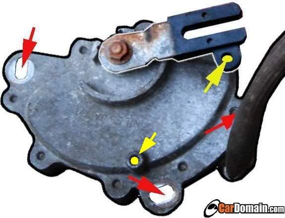
lining up the yellow holes = neutral. for manual valve arm you turn it all the way clockwise then counterclockwise 2 clicks for neutral. the red holes are for adjustment of the position of the inhibitor. That's why you align the manual valve arm first, then rotate the inhibitor until the yellow holes line up perfectly and then tighten it down. then attach the shifter cable.
i'll get a pic of the manual valve arm stuff tonight.
Last edited by CapedCadaver; Apr 15, 2008 at 08:45 AM.
