
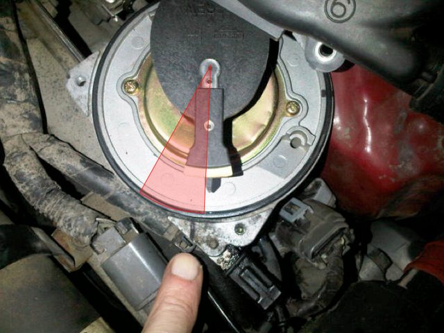
Changing the timing belt and I'm going through the TDC procedure. I've got the #1 piston at TDC by moving the crankshaft "0" mark under the timing pointer. However, when I look at the distributor rotor it doesn't point exactly to the mark I made indicating where the #1 cylinder wire pokes out under the distributor cap. My question is whether the rotor needs to be pointed directly at the mark? See image where my finger points to the mark indicating where the #1 cylinder wire exits under the cap.

Ad�min�is�tra�tor
so the factory ignition spec is like 15 degrees BTDC right?
if that's the case it will probably never be perfectly on the mark...you know what i'm saying?
if that's the case it will probably never be perfectly on the mark...you know what i'm saying?

Quote:
http://www.nicoclub.com/FSM/Maxima/1994/em.pdfOriginally Posted by redhunter
Changing the timing belt and I'm going through the TDC procedure. I've got the #1 piston at TDC by moving the crankshaft "0" mark under the timing pointer. However, when I look at the distributor rotor it doesn't point exactly to the mark I made indicating where the #1 cylinder wire pokes out under the distributor cap. My question is whether the rotor needs to be pointed directly at the mark? See image where my finger points to the mark indicating where the #1 cylinder wire exits under the cap.
According to the FSM that's the cyl#4 position. Look at EM-32 the "TDC Cyl 1" position is pointing towards the crank pulley. Cyl 1 and 4 top out at the same time, so turning the crank 360 degrees will move the disty another 180.
Also keep in mind that the disty cap on our car is really strangely laid out.. like the traces criss cross and zig zag under the cap so the plug wires don't have to. Were you looking at the #1 wire position from the outside of the cap, or tracing it via the inside?
On the upside-down pic, #1 is coming up from the bottom left. You can "kinda" see the dark spots on the top side of the cap where those traces are.

Either way the rotor tip is SUPER wide on our cars so the ECU can electronically adjust the timing (sparking at any point within that wide tip's travel past the wire post) so like Danny said, our factory timing is 15 degrees before TDC.

Quote:
Thanks for the info. I did confirm that rotor is pointing at the Cyl #1 wire. On my Nissan OEM distributor cap the #1 wire doesn't crisscoss; it exits about 1/2" to the right of the "1" in picture. In this picture I laid the cap on top of the rotor to show how it was orientated when I removed it. The FSM picture you reference does show the rotor pointed to #1 in a different position (although not 180 degrees different - more like 120. Also the FSM picture looks odd in that there are only 2 holes to screw down the cap; mine has 3.Originally Posted by CapedCadaver
According to the FSM that's the cyl#4 position. Look at EM-32 the "TDC Cyl 1" position is pointing towards the crank pulley.

Quote:
hmmm yea i see what you mean about the FSM picture, that is kinda weird Originally Posted by redhunter
Thanks for the info. I did confirm that rotor is pointing at the Cyl #1 wire. On my Nissan OEM distributor cap the #1 wire doesn't crisscoss; it exits about 1/2" to the right of the "1" in picture. In this picture I laid the cap on top of the rotor to show how it was orientated when I removed it. The FSM picture you reference does show the rotor pointed to #1 in a different position (although not 180 degrees different - more like 120. Also the FSM picture looks odd in that there are only 2 holes to screw down the cap; mine has 3.
 oh well. It wouldn't be the first time something in the FSM seemed a bit off (the labels for the wire colors on the A/T inhibitor switch on a VG are also wrong - it calls reverse yellow/black instead of red/black). Granted technically it is true that #1 TDC and #4 TDC happen at the same time, but I always assumed that it was referencing the end of the compression stroke (when the spark happens) on the camshaft sprockets.
So yea, that does look right for #1 after all. So must just be what Danny said... the static timing offset of 15 degrees.
Ad�min�is�tra�tor
Quote:
oh well. It wouldn't be the first time something in the FSM seemed a bit off (the labels for the wire colors on the A/T inhibitor switch on a VG are also wrong - it calls reverse yellow/black instead of red/black). Granted technically it is true that #1 TDC and #4 TDC happen at the same time, but I always assumed that it was referencing the end of the compression stroke (when the spark happens) on the camshaft sprockets.
So yea, that does look right for #1 after all. So must just be what Danny said... the static timing offset of 15 degrees.
c'mon...60% of the time i'm right every time Originally Posted by CapedCadaver
hmmm yea i see what you mean about the FSM picture, that is kinda weird oh well. It wouldn't be the first time something in the FSM seemed a bit off (the labels for the wire colors on the A/T inhibitor switch on a VG are also wrong - it calls reverse yellow/black instead of red/black). Granted technically it is true that #1 TDC and #4 TDC happen at the same time, but I always assumed that it was referencing the end of the compression stroke (when the spark happens) on the camshaft sprockets.So yea, that does look right for #1 after all. So must just be what Danny said... the static timing offset of 15 degrees.

btw OP, did you remove the distributor while you were working on the car, or did you leave it installed the whole time? and have you started the car yet since working on it?
but anyways i think you are fine.... your black mark is well within the sweep of the rotor.. remember it spins counter-clockwise and you are indicating "TDC" rather than "15˚ BTDC" (15˚ on the crank = 7.5˚ on the camshaft/disty) So your at-idle ignition point would be 7.5˚ ahead of where your black mark is, and it advances a little more as RPM climbs so you'd be further ahead still.
30˚ BTDC (-15˚ @ distributor)
14˚ BTDC (-7˚ @ distributor)
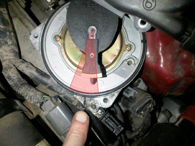
0˚ TDC
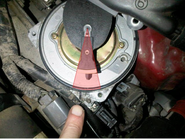
30˚ BTDC (-15˚ @ distributor)
14˚ BTDC (-7˚ @ distributor)
0˚ TDC
Quote:
Na, since my 16 yr old drives this car I should probably retard the timing. Originally Posted by Richy Rich
When you get it re-assembled, do you plan to bump the timing for a little more power?

Quote:
No, not the entire distributor. I just removed the cap to perform the TDC procedure.Originally Posted by CapedCadaver
btw OP, did you remove the distributor while you were working on the car
Quote:
No, still working on the timing belt.Originally Posted by CapedCadaver
and have you started the car yet since working on it?
Again, thanks for your help on this. It will certainly remove a lot of anxiety when I do start the car again.
Quote:
Once I put the new timing belt on I assume. I haven't quite got there yet�I had 3 missing timing belt cover bolts, which I had to order.Originally Posted by DanNY
OP...hang turn the crank for 4 full strokes...if it doesn't bind "usually" you're ok.
Ad�min�is�tra�tor
Quote:
yessssss...after the belt and everything else is on. this is before you turn the key.Originally Posted by redhunter
Once I put the new timing belt on I assume. I haven't quite got there yet—I had 3 missing timing belt cover bolts, which I had to order.
sorry that i wasn't clear.

Senior Member
Quote:
You have a 1990 Maxima. The 94 manual only covers 92-94 wiring. There are many differences in the electrical system for those years, including wire color changes. If you still have your Max, you should be using the correct FSM. Especially when it comes to electrical info.Originally Posted by CapedCadaver
It wouldn't be the first time something in the FSM seemed a bit off (the labels for the wire colors on the A/T inhibitor switch on a VG are also wrong - it calls reverse yellow/black instead of red/black).
I can confirm that wire is labeled r/b in my 91 manual.
Quote:
I can confirm that wire is labeled r/b in my 91 manual.
actually it's just me being stupid, and forgetting that the connectors are mirror images of each other.... i was looking at the top-right pin on both sides of the diagram, instead of top-right on the upper and bottom-right of the lower Originally Posted by Hectic
You have a 1990 Maxima. The 94 manual only covers 92-94 wiring. There are many differences in the electrical system for those years, including wire color changes. If you still have your Max, you should be using the correct FSM. Especially when it comes to electrical info.I can confirm that wire is labeled r/b in my 91 manual.

I was looking at the wire for 2nd gear, not reverse. And it took me 5 years to realize it
