So...who wants a gear indicator in the cluster?
#242


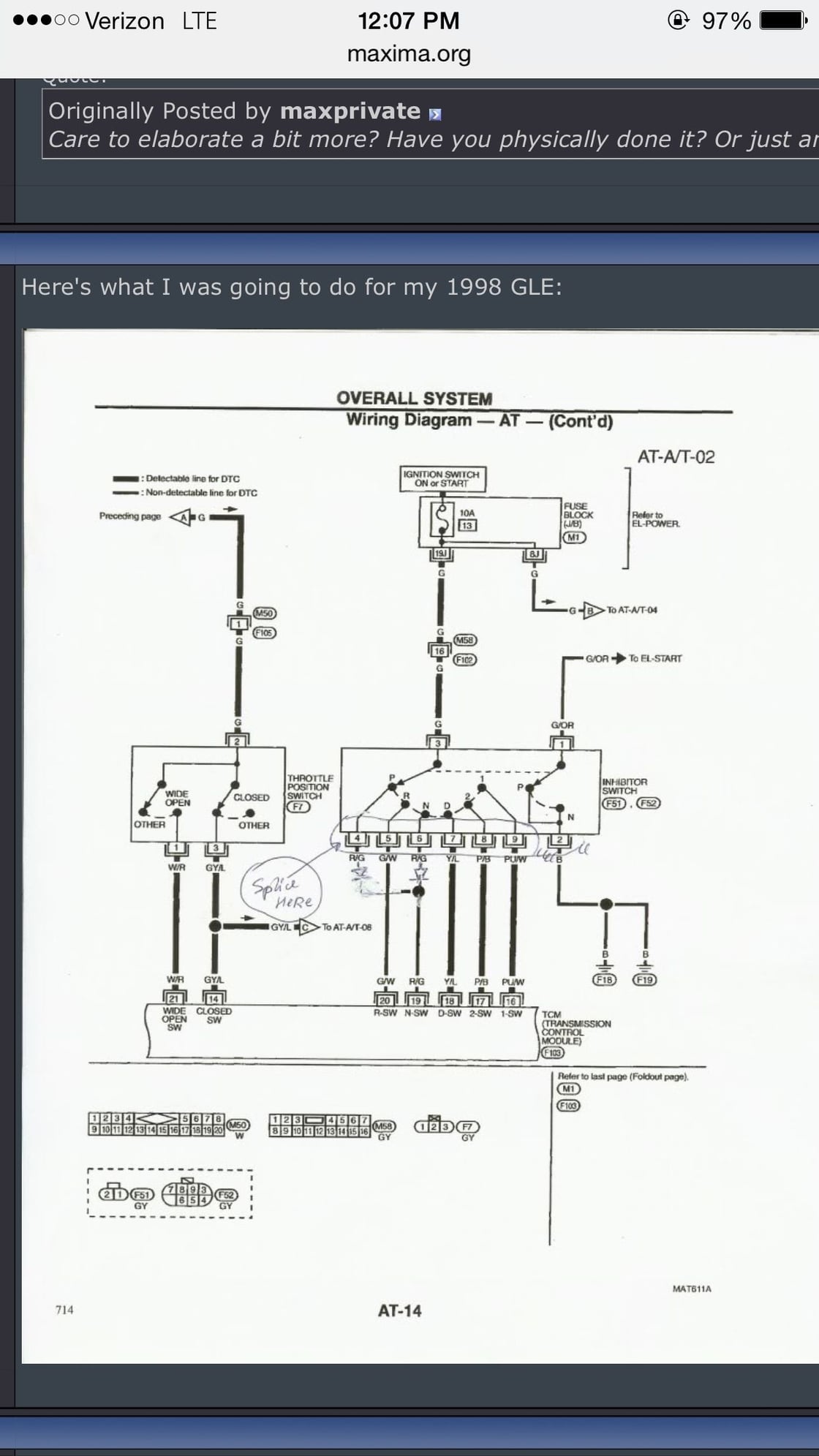
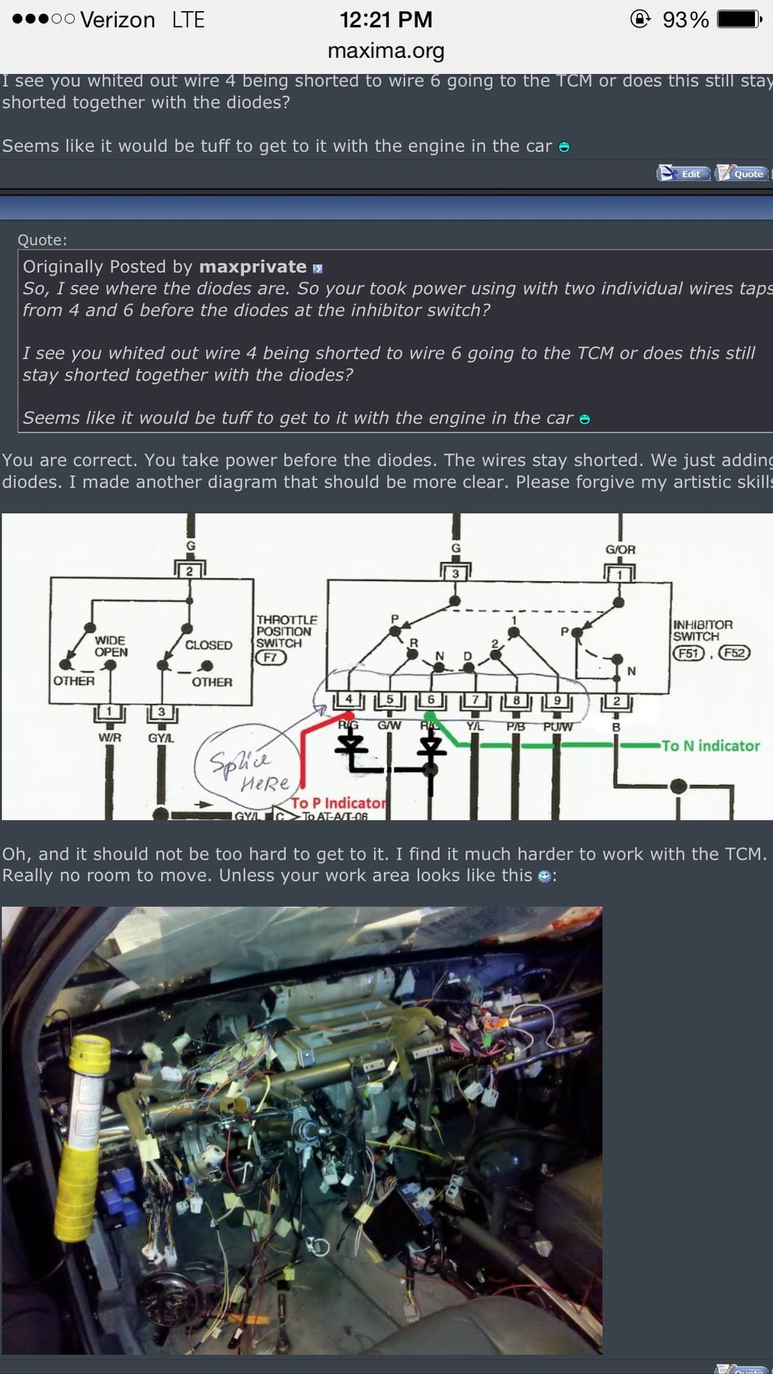
Ok so it's been quite a few years but in the middle of an engine swap I was easily able to access the inhibitor switch to add the diodes. This will isolate the Park and neutral indicator lights in the gear display so they no longer both come on at the same time whether in Park or Nuetral. I'm not sure if I put the diodes cathode in the correct direction. <br/><br/>If power comes from the 52 plug which I think it does then the cathode of the diode is in the wrong direction. Any thoughts ?
#245
Haha I can post some instructions when it's 100 percent working. 
Hopefully these diodes will seperate the Park and Nuetral signal. Other than that it worked flawlessly.
Any thoughts on if the diodes I installed are in the correct direction?
My build is finally almost done so once I have my car back I'll verify If what I did works or not.
POtatoehead, it's really not difficult at all, only issue would be to install the diodes which has to be done under the car at the inhibitor switch but I'm sure you can use the Wiz lift to get under there.

#246
 success guys it works! The neutral light no longer comes on with the park indicator light in the gear display. The picture i posted is exactly where you need to solder the 2 diodes. The diagram is in this thread, thanks to all those that helped me out with this. To bad to the guys are no longer around but I couldn't have done it without you guys.
#247
Licensed to Spell


iTrader: (12)
Join Date: Feb 2001
Location: Murrieta (southern California)
Posts: 4,521
 success guys it works! The neutral light no longer comes on with the park indicator light in the gear display. The picture i posted is exactly where you need to solder the 2 diodes. The diagram is in this thread, thanks to all those that helped me out with this. To bad to the guys are no longer around but I couldn't have done it without you guys.
Great job mp. Very nice. Thanks for the update. Is there anyway you can do a dummy-proof write-up with clear step-by-step explanations, pics, parts/tools list, etc? Thanks!
#248
You can run 6 separate wires right up to the cluster from the firewall in the engine bay driver side. Luckily its easier to get all the signals there versus taking the signals from the TCM like I did. But park and neutral must come from the inhibitor switch where you add the diodes.
The diodes are N4 something ( can't remember the exact part number but any should work) I believe from radio shack. For wire size I would use 16 gauge stranded wire, you can get fancy and use color coded wire ( expensive ) or just label them so you don't get confused on whats for what.. You solder the diodes exactly where I did and take your P and N wire running up to the cluster prior to the diodes. Make sure your wires are long enough! maybe 6' each wire are good but dont quote me on that check and make sure.
Now for adding these wires to the cluster, looking on the back of the PCB on the cluster you can trace the corresponding P N R D 2 1 signals to each harness plug ( they are not all located on the same gauge harness plug ). You'll need a spare gauge cluster harness plug to salvage the pin wires to do the pin out. On your harness plugs for the cluster there should be no wires existing in those pin locations just push the wire right in and they should lock in place. Make sure you cut your wire long enough on the spare harness plug you get, I would say 6 to 12 inches is fine to work with.
Then, solder the wires coming from the inhibitor switch you added and ran into the cluster to the corresponding pin out wires you added to the stock gauge harness plug. At this point you're good to go, tuck all your wires neatly away and enjoy a job well and long over due


Last edited by maxprivate; 11-29-2015 at 04:53 PM.
#249
Licensed to Spell


iTrader: (12)
Join Date: Feb 2001
Location: Murrieta (southern California)
Posts: 4,521
Ptatohead, Im way to busy to do a full write up pics etc. But I can tell you from post 234,235 ( inhibitor switch diagram ) and post 231 ( actual inhibitor switch ) everything you need regarding where to get the signals for the gear display is right there as well as how to add the diodes for Park and Neutral. I have a 97 so color code were different.
You can run 6 separate wires right up to the cluster from the firewall in the engine bay driver side. Luckily its easier to get all the signals there versus taking the signals from the TCM like I did. But park and neutral must come from the inhibitor switch where you add the diodes.
The diodes are N4 something ( can't remember the exact part number but any should work) I believe from radio shack. For wire size I would use 16 gauge stranded wire, you can get fancy and use color coded wire ( expensive ) or just label them so you don't get confused on whats for what.. You solder the diodes exactly where I did and take your P and N wire running up to the cluster prior to the diodes. Make sure your wires are long enough! maybe 6' each wire are good but dont quote me on that check and make sure.
Now for adding these wires to the cluster, looking on the back of the PCB on the cluster you can trace the corresponding P N R D 2 1 signals to each harness plug ( they are not all located on the same gauge harness plug ). You'll need a spare gauge cluster harness plug to salvage the pin wires to do the pin out. On your harness plugs for the cluster there should be no wires existing in those pin locations just push the wire right in and they should lock in place. Make sure you cut your wire long enough on the spare harness plug you get, I would say 6 to 12 inches is fine to work with.
Then, solder the wires coming from the inhibitor switch you added and ran into the cluster to the corresponding pin out wires you added to the stock gauge harness plug. At this point you're good to go, tuck all your wires neatly away and enjoy a job well and long over due


 ), and let you know if I have any questions. Thanks again.
#252
Licensed to Spell


iTrader: (12)
Join Date: Feb 2001
Location: Murrieta (southern California)
Posts: 4,521
Here is one using an Arduino unit, haven't looked up the instructions/write-up yet and hope there is one. Not necessary at all but fun to look at and would be a challenging project it seems:
Gearshift Indicator for manual transmission - YouTube
Gearshift Indicator for manual transmission - YouTube

Thread
Thread Starter
Forum
Replies
Last Post
jmlee44
4th Generation Maxima (1995-1999)
8
10-02-2022 02:13 PM
CAN-Toronto FS: Basement cleaning
knight_yyz
5th Generation Classifieds (2000-2003)
12
11-01-2015 01:34 PM


