
HOW TO: Custom A32 Large Bore MAF


HOW TO: Custom A32 Large Bore MAF
I will not be responsible for any thing that happens to you, your car, or any other piece of your property that occurs before, during or after making, assembling, testing and/or using this MAF.
This is a short but sweet write up I made for you peeps wanting your own large bore MAF. I have yet to test it, I have no Air/Fuel controller.
Parts:
Your new MAF tube
Your current(or spare) MAF housing
Saw zaw/hack saw
Drill and/or router
The housing:
Inner Diameter: 3 3/8"
Outer Diameter: 3 1/2"
Length: 6"
Using the STOCK sensor.
So, lets get on with it.
How To:
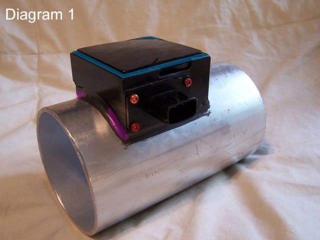
1. Use a razor or exacto knife(#11 blade works well) to remove the seal around the edge of the cap. The seal is highlighted in blue on diagram 1.
2. Use the combination of a small flat head screw driver and your exacto knife to pry open the cap. You can see from the picture, I accidentally broke the wall of mine, this is no big deal as once I get it running, I am going to seal it back off with liquid gasket.
3. Remove the four outer screws on the plug itself. Be careful not to strip them, they arent easy. These are highlighted in red on diagram 1. DO NOT PULL ON THE PLUG!
4. Next, there will be a brass protector just under the plastic cap you just removed. It comes straight out, but may need some prying.
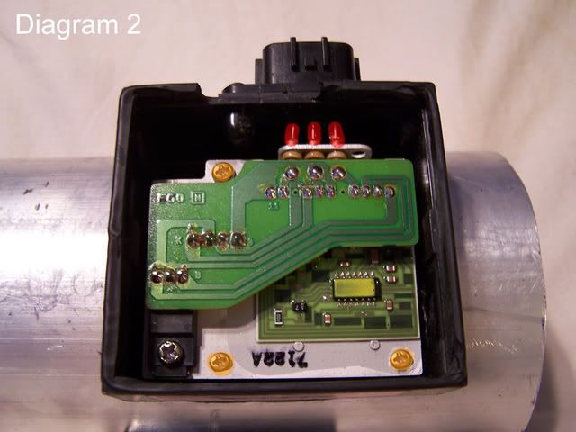
5. Here comes the harder part. You need to disconnect the main harness from the inside circuitry. The three contacts are highlighted in red in diagram 2. You have two options here:
a. The easy/fast yet risky way: Use a small flathead screw driver to break the 3 contacts to the plug from the leads off of the main circuit board. Just pry. They will come off. But too much stress and they will break. If they do, you will need to solder a new connection in.
b. The proper way: Simply use a soldering iron to heat up the solder joint, while using a small flathead to pry at the same time. No breaking, no risk.
6. Remove the three screws in the main circuit board. These are highlighted in orange in diagram 2.
7. Use a medium flathead to CAREFULLY! pry the main circuit board out of the housing. There is a rubber seal, and what I believe is locktite holding it in. Stick the screwdriver through the hole where the sensor plug came out of.
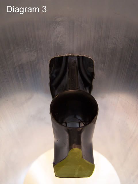
8. Set everything off to the side. Take your empty MAF housing and use a hack saw, saw zaw or other appropriate tool to cut plastic to make your cuts. I just did mine flush with the walls of the housing(seen is diagram 1). I then cut the sensor post from the inside of the housing. (yellow highlight, seen in diagram 3)
9. For me, this was the longest part. I am a perfectionist. What happens is, since the diameter of the black MAF tube was smaller than the large one, this means that the sensor housing will not sit nice and flush with your new tube. So I used a bench grinder to get the right shape. You can see where I grinding out, diagram 1, highlighted in pink.
10. Almost there, now just mark your hole on your new housing. I use an aluminum housing, PVC can cause harmful fumes, not to mention it doesnt resist heat well. I used a drill bit and a router to cut my hole. I just kept test fitting until it fit nicely.
11. Last step. Use some super glue to secure the sensor housing to the new tube. Once it is dry, use liquid gasket, or similar, to make an appropriate seal around the edge.
Finally, just reassemble everything with caution, and don't forget to re-solder the plug so it will work!
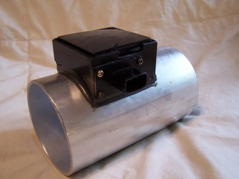
The Final Product:
This is a short but sweet write up I made for you peeps wanting your own large bore MAF. I have yet to test it, I have no Air/Fuel controller.
Parts:
Your new MAF tube
Your current(or spare) MAF housing
Saw zaw/hack saw
Drill and/or router
The housing:
Inner Diameter: 3 3/8"
Outer Diameter: 3 1/2"
Length: 6"
Using the STOCK sensor.
So, lets get on with it.
How To:
1. Use a razor or exacto knife(#11 blade works well) to remove the seal around the edge of the cap. The seal is highlighted in blue on diagram 1.
2. Use the combination of a small flat head screw driver and your exacto knife to pry open the cap. You can see from the picture, I accidentally broke the wall of mine, this is no big deal as once I get it running, I am going to seal it back off with liquid gasket.
3. Remove the four outer screws on the plug itself. Be careful not to strip them, they arent easy. These are highlighted in red on diagram 1. DO NOT PULL ON THE PLUG!
4. Next, there will be a brass protector just under the plastic cap you just removed. It comes straight out, but may need some prying.
5. Here comes the harder part. You need to disconnect the main harness from the inside circuitry. The three contacts are highlighted in red in diagram 2. You have two options here:
a. The easy/fast yet risky way: Use a small flathead screw driver to break the 3 contacts to the plug from the leads off of the main circuit board. Just pry. They will come off. But too much stress and they will break. If they do, you will need to solder a new connection in.
b. The proper way: Simply use a soldering iron to heat up the solder joint, while using a small flathead to pry at the same time. No breaking, no risk.
6. Remove the three screws in the main circuit board. These are highlighted in orange in diagram 2.
7. Use a medium flathead to CAREFULLY! pry the main circuit board out of the housing. There is a rubber seal, and what I believe is locktite holding it in. Stick the screwdriver through the hole where the sensor plug came out of.
8. Set everything off to the side. Take your empty MAF housing and use a hack saw, saw zaw or other appropriate tool to cut plastic to make your cuts. I just did mine flush with the walls of the housing(seen is diagram 1). I then cut the sensor post from the inside of the housing. (yellow highlight, seen in diagram 3)
9. For me, this was the longest part. I am a perfectionist. What happens is, since the diameter of the black MAF tube was smaller than the large one, this means that the sensor housing will not sit nice and flush with your new tube. So I used a bench grinder to get the right shape. You can see where I grinding out, diagram 1, highlighted in pink.
10. Almost there, now just mark your hole on your new housing. I use an aluminum housing, PVC can cause harmful fumes, not to mention it doesnt resist heat well. I used a drill bit and a router to cut my hole. I just kept test fitting until it fit nicely.
11. Last step. Use some super glue to secure the sensor housing to the new tube. Once it is dry, use liquid gasket, or similar, to make an appropriate seal around the edge.
Finally, just reassemble everything with caution, and don't forget to re-solder the plug so it will work!
The Final Product:
Last edited by MOHFpro90; May 15, 2008 at 08:14 PM.

Thats my pipe, so i deserve some credit, cause it was my money that bought it. 
Nice job dude. It should be noted no one should do this with out proper tuning. He is not responsible if you go lean and you blow your engine. So tune your car.
Nice job dude. It should be noted no one should do this with out proper tuning. He is not responsible if you go lean and you blow your engine. So tune your car.


SOON as i saw this.. I wanted to make one... then I thought this mod would become a lot more expensive cause i would now be FORCED to get Greddy EU...
Great pictures by the way... I mean I will remember how you made this no matter how long it takes me to get to the point where I need to do this...
Great pictures by the way... I mean I will remember how you made this no matter how long it takes me to get to the point where I need to do this...


so this is probably not too safe without tuning? sorry, dont know much about MAF and its readings,  ....
....
also, is the MAf screen just no longer usable? not really needed? wish we could re-use it? like i said...
....also, is the MAf screen just no longer usable? not really needed? wish we could re-use it? like i said...
Bigpulve, dont worry, I am. Oh, and I do have a spare piece of pipe, I just need to get a spare MAF and Ill make you one. As long as Dave doesnt want the piece of pipe back.
HomerMac, I have yet to know if its worth it, but it was sure as heck fun making it. Haha.
Maximaspeed85, yeah it would not run well(if run at all) without a tune. Far too lean.
And mesh is always an option, but not really needed. Your filter should filter it.
HomerMac, I have yet to know if its worth it, but it was sure as heck fun making it. Haha.
Maximaspeed85, yeah it would not run well(if run at all) without a tune. Far too lean.
And mesh is always an option, but not really needed. Your filter should filter it.
Last edited by MOHFpro90; May 15, 2008 at 11:21 PM.


Seems like overkill for an NA engine and also using the stock sensor.
Also, why would you use super glue to attach the plastic housing to the aluminum piping? Why not use something more durable such as JB Weld or etc.?
Also, why would you use super glue to attach the plastic housing to the aluminum piping? Why not use something more durable such as JB Weld or etc.?
also note that there is a small blade on the sensor right before the resistor, that is also there to direct the air flow in a straight line before hitting the sensor.
heres a pic of what im talking about.

Last edited by black_maxed95; May 16, 2008 at 07:19 AM.
Also, since this thing is about he same size as the LRMAF, looking at his design, one could easily (with enough time and detail, as the OP has represented here) do this w/ the LRMAF, which indeed has a honeycomb / mesh, etc you speak of.
BTW, this thing must be MASSIVE, (85mm ID), so be VERY careful, ESPECIALLY w/o any AFR control / monitoring.
Last edited by NmexMAX; May 16, 2008 at 09:44 AM.
JB weld doesnt hold well to smoother surfaces. The superglue holds very well, thats the least of my worries.

Thread
Thread Starter
Forum
Replies
Last Post
TallTom
5th Generation Maxima (2000-2003)
57
Oct 14, 2025 05:16 PM
James92SE
3rd Generation Maxima (1989-1994)
142
Jan 2, 2024 09:23 AM
BPuff57
Advanced Suspension, Chassis, and Braking
33
Apr 16, 2020 05:15 AM