
9004 To 9007 Headlights Conversion Write-Up


Thread Starter
Junior Member
Joined: Nov 2010
Posts: 48
From: Mount Prospect, IL
9004 To 9007 Headlights Conversion Write-Up
So I've been gone a while, have been meaning to post on the .org. So anyway I took it upon myself to make use of some semi-blue 9007 bulbs laying around left by one of my dads customers. The result is great, not to much work involved and inexpensive to do. You'll need to have some butt connectors, some crimpers, electrical tape, file, possibly new sockets if they are melted, and of course the bulbs  . I did all of this on my 97' SE, but it should be the same on all 4th gens.
(WARNING: Please for the love that is holy DO NOT get aftermarket sockets, they have **** poor connection to the bulbs themselves and create the illusion you did something wrong when they don't work. Got pulled over because the socket didn't work . If you need new sockets, go to a junkyard and get Ford Sockets, they last MUCH longer.)
Basically all you need to do is to take the wire for the low beam and the ground on the socket and switch them. If you flip the socket upside down (the tab that keeps the light fastened is facing the ground) the wiring is as follows: High, Low, Ground. That's all. The wiring for each headlight is as follows:
Driver's headlight (Wiring during the switch):
Yellow: High-Beam
Green: Low-Beam
Black: Ground

Passenger's headlight (Wiring before the switch):
Green: High-Beam
Blue: Low-Beam
Black: Ground

When you crimp everything together you'll have a noticeable difference in lighting, the extra 10 watts to 55 definitely helps. Before you put the lights in you have to file the two nubs at the bottom of the housing where the light goes before you put it in. Then cover the crimped areas in electrical tape to prevent any corrosion. Here are some pictures comparing my old 9004s (Passenger Side) To one of the 9007s (Driver Side)
Low Beam:

High Beam:


Enjoy the new headlights and the new 9007 lights firin its lazors at you, lol.
. I did all of this on my 97' SE, but it should be the same on all 4th gens. (WARNING: Please for the love that is holy DO NOT get aftermarket sockets, they have **** poor connection to the bulbs themselves and create the illusion you did something wrong when they don't work. Got pulled over because the socket didn't work
. If you need new sockets, go to a junkyard and get Ford Sockets, they last MUCH longer.)Basically all you need to do is to take the wire for the low beam and the ground on the socket and switch them. If you flip the socket upside down (the tab that keeps the light fastened is facing the ground) the wiring is as follows: High, Low, Ground. That's all. The wiring for each headlight is as follows:
Driver's headlight (Wiring during the switch):
Yellow: High-Beam
Green: Low-Beam
Black: Ground
Passenger's headlight (Wiring before the switch):
Green: High-Beam
Blue: Low-Beam
Black: Ground
When you crimp everything together you'll have a noticeable difference in lighting, the extra 10 watts to 55 definitely helps. Before you put the lights in you have to file the two nubs at the bottom of the housing where the light goes before you put it in. Then cover the crimped areas in electrical tape to prevent any corrosion. Here are some pictures comparing my old 9004s (Passenger Side) To one of the 9007s (Driver Side)
Low Beam:
High Beam:
Enjoy the new headlights and the new 9007 lights firin its lazors at you, lol.
Last edited by Dillano609; Sep 15, 2011 at 03:24 PM.


OR,
and,
Cutting and crimping is a meltdown waiting to happen. You will introduce resistance, which will cause heat and start melting insulation. Corrosion could also insue and cause the wire to sever, and possibly short to ground.
OK so I decided to get the sockets off my parts car in the woods to show how to remove the wires from the socket since it can be tricky.
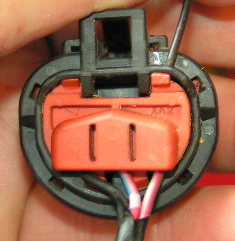
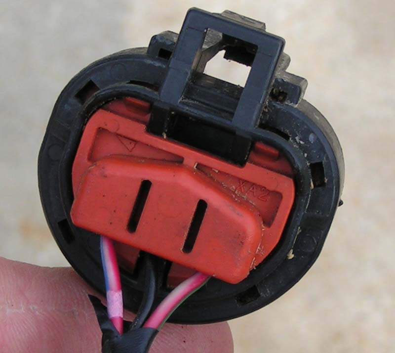
the first step is to push down and out on one of the tabs that holds the orange clip in:
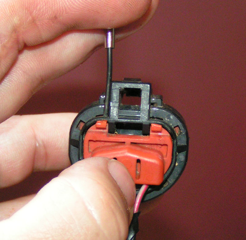
Next you do the same thing to the other side:
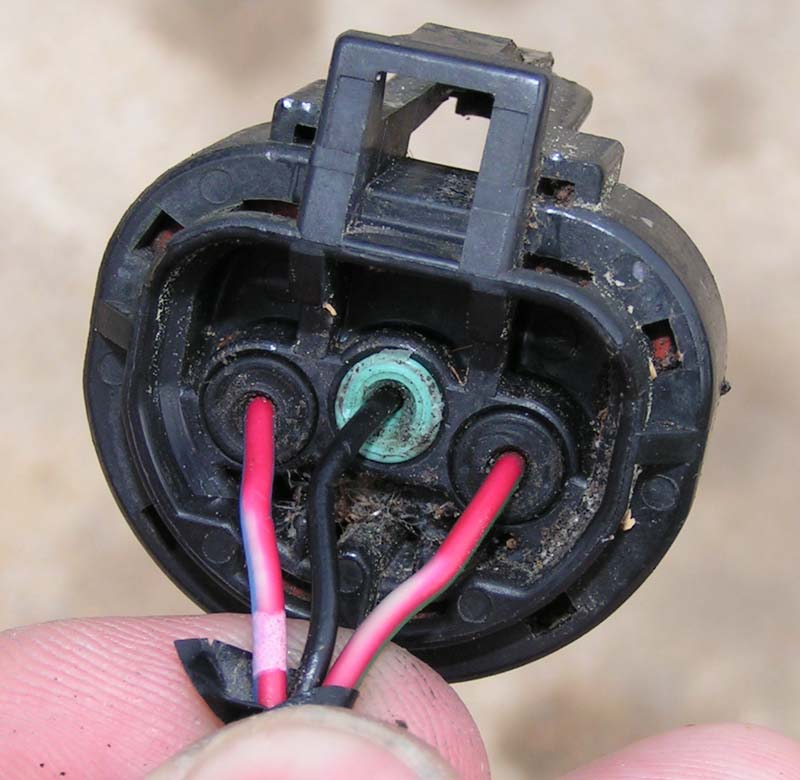
Here is a shot of the back of the socket without the clip in place (its been sitting in the weather for several years...yours will probably not have the junk behind it):
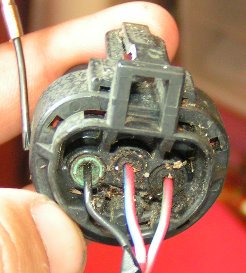
Next you will need a thin piece that comes to a point like a thick needle or something. This is important because you have to get under the clip or you will not be able to lift it...a thumb tack will work if its long enough.
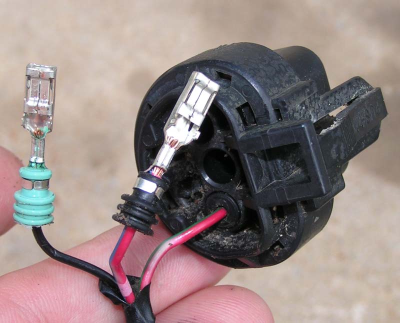
you angle the tip down until you get under the clip that holds the wire in place and then lift up and pull the wire right out:
the first step is to push down and out on one of the tabs that holds the orange clip in:
Next you do the same thing to the other side:
Here is a shot of the back of the socket without the clip in place (its been sitting in the weather for several years...yours will probably not have the junk behind it):
Next you will need a thin piece that comes to a point like a thick needle or something. This is important because you have to get under the clip or you will not be able to lift it...a thumb tack will work if its long enough.
you angle the tip down until you get under the clip that holds the wire in place and then lift up and pull the wire right out:
here is a pic of the wires out of the socket ready to be swapped:
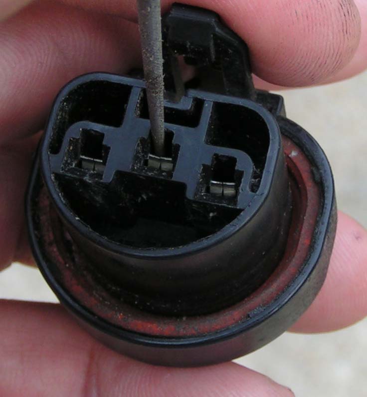
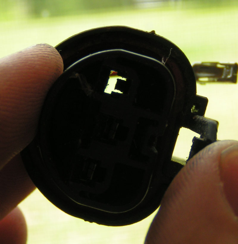
here is a pic looking into the socket to show the clip that has to be raised to get the wire out (not the correct wire out but its just to show how the clip looks to give you a better idea of where it is):
Here are the wires swapped:
Here it is with the cap back on and the socket ready to be used:
here is a pic looking into the socket to show the clip that has to be raised to get the wire out (not the correct wire out but its just to show how the clip looks to give you a better idea of where it is):
Here are the wires swapped:
Here it is with the cap back on and the socket ready to be used:
Last edited by asand1; Sep 15, 2011 at 01:21 PM.

 ). Solder the wires and use shrink tubing.
The connecter clips go on top. Trim the two lower (5 and 8 o'clock) nubs in the housing off. Both 9004 and 9007 have a nub at 12 o'clock, and this is what you will need to locate the bulb in the housing.

Solder would be second best (and my favorite wire splice technique), but leaves the possibility of the wire breaking off at the solder joint. Its SO easy to swap the wires, and totally reversible.
Thread Starter
Junior Member
Joined: Nov 2010
Posts: 48
From: Mount Prospect, IL
 Either way, thanks for providing an alternative
This is true, but the shrink tubing is stiff and adds strength to the connection by keeping flexing away from the solder area. I have seen bad solder connections caused by people using a soldering iron that is too hot, thereby crystalizing the wire. For the size wires used in this thread, a 10 watt soldering iron is fine, a 15 watt is ok. When you are using too hot of an iron, the plastic insulation on the wire starts melting before you can apply the solder. Those Weller 240 watt soldering guns that I have seen some mechanics use are for battery cables and regrooving tires.

This is true, but the shrink tubing is stiff and adds strength to the connection by keeping flexing away from the solder area. I have seen bad solder connections caused by people using a soldering iron that is too hot, thereby crystalizing the wire. For the size wires used in this thread, a 10 watt soldering iron is fine, a 15 watt is ok. When you are using too hot of an iron, the plastic insulation on the wire starts melting before you can apply the solder. Those Weller 240 watt soldering guns that I have seen some mechanics use are for battery cables and regrooving tires.

Thread
Thread Starter
Forum
Replies
Last Post
doctorpullit
8th Generation Maxima (2016-)
21
Oct 28, 2019 10:58 PM
trsandrew
7th Generation Maxima (2009-2015)
17
Apr 8, 2016 06:45 PM
trsandrew
Group Deals / Sponsors Forum
2
Oct 25, 2015 02:47 PM
Calabar
4th Generation Classifieds (1995-1999)
3
Oct 5, 2015 09:57 PM