
OBD2 Scan Port Malfunction Mystery Solved


Thread Starter
Senior Member
Joined: Jan 2011
Posts: 3,037
From: Central AR
OBD2 Scan Port Malfunction Mystery Solved
Last night while driving Max IV, the check engine light came on. I suspected it was another Evap system related code. So I go home and plug in my OBD2 scanner. The scanner fails to connect. I had no scanner lights, no scanning, no activity from the reader. Oh great. It seemed like the OBD2 port was dead. It was.
Next I tried the scanner on Max III and it worked as expected. So this is a Max IV specific problem.
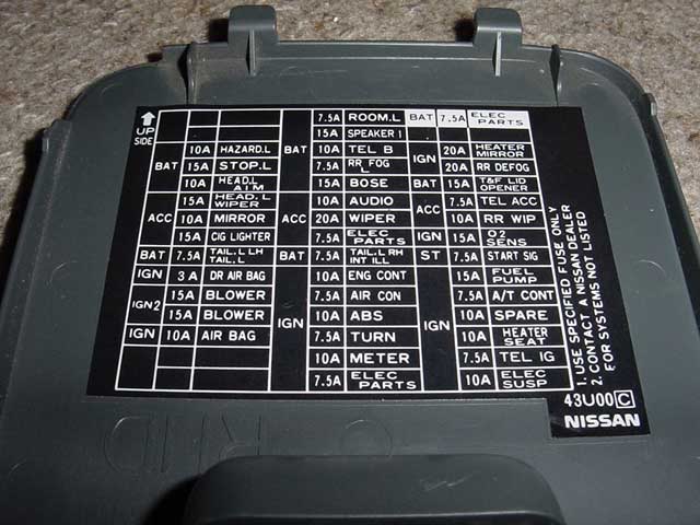
To rewind a couple of weeks when I was working on an antenna replacement, I managed to blow a couple of 7.5 fuses in a slot named ELEC PARTS. This fuse is located on the 3rd row from the right at the top. The clock will not function if this fuse is blown. Since I knew I had a blown 7.5 amp fuse, I picked up a 3-pack of fuses a couple of days earlier. I had already planned to replace the fuse to get the clock running this weekend.
Here's a picture from Kevlo911 that shows the ELEC PARTS fuse location.
Since I have an ELEC PARTS blown fuse and a non-working OBD2 port, there must be a connection. It turns out there is.
After replacing the 7.5 amp ELEC PARTS fuse, the OBD2 port and clock now work.
If your clock suddenly stops working, it may be caused by a blown ELEC PARTS fuse. The 7.5 amp fuse can be blown by a short in the radio antenna. Fix the short and replace the fuse as soon as possible so the clock and the OBD2 port will work. You never know when you might need to use an OBD2 scanner to check and reset a code.
Next I tried the scanner on Max III and it worked as expected. So this is a Max IV specific problem.
To rewind a couple of weeks when I was working on an antenna replacement, I managed to blow a couple of 7.5 fuses in a slot named ELEC PARTS. This fuse is located on the 3rd row from the right at the top. The clock will not function if this fuse is blown. Since I knew I had a blown 7.5 amp fuse, I picked up a 3-pack of fuses a couple of days earlier. I had already planned to replace the fuse to get the clock running this weekend.
Here's a picture from Kevlo911 that shows the ELEC PARTS fuse location.
Since I have an ELEC PARTS blown fuse and a non-working OBD2 port, there must be a connection. It turns out there is.
After replacing the 7.5 amp ELEC PARTS fuse, the OBD2 port and clock now work.
If your clock suddenly stops working, it may be caused by a blown ELEC PARTS fuse. The 7.5 amp fuse can be blown by a short in the radio antenna. Fix the short and replace the fuse as soon as possible so the clock and the OBD2 port will work. You never know when you might need to use an OBD2 scanner to check and reset a code.
Last edited by CS_AR; Oct 17, 2016 at 08:31 AM.

Exactly. As you probably know, most of the fuses run more than one thing. You just found another example.
The OBD connector in the car has to have 12 volts on pin 16. The OBD reader looks for this as a way of knowing it has been plugged in.
And did you know that in addition to fuse # 40 making the clock work, the clock also needs power from a 2nd fuse, # 21. Makes things interesting.
The OBD connector in the car has to have 12 volts on pin 16. The OBD reader looks for this as a way of knowing it has been plugged in.
And did you know that in addition to fuse # 40 making the clock work, the clock also needs power from a 2nd fuse, # 21. Makes things interesting.

Senior Member
Joined: Mar 2014
Posts: 633
From: Planet Houston
My clock doesnt work. It used to, and then it needed to be reset all the time, and now it doesnt light up at all.
Both referenced fuses are intact. Pretty sneaky the way those are numbered - had to pull out the FSM.
Is there a secret beyond disassembling dash and checking for voltage at clock wiring terminal ends?
Both referenced fuses are intact. Pretty sneaky the way those are numbered - had to pull out the FSM.
Is there a secret beyond disassembling dash and checking for voltage at clock wiring terminal ends?
Nissan started using that clock in the 3rd gen Maximas and so many of us discovered that the clock's printed circuit board suffered from cold solder joints. Moving up to the 4th gen Maxima, we were disappointed to learn that the cold solder problem still existed.
I wouldn't be surprised if that is your problem. After I removed and re-soldered the clock in my 97 - no more problems.
I wouldn't be surprised if that is your problem. After I removed and re-soldered the clock in my 97 - no more problems.
Thread Starter
Senior Member
Joined: Jan 2011
Posts: 3,037
From: Central AR
Nissan started using that clock in the 3rd gen Maximas and so many of us discovered that the clock's printed circuit board suffered from cold solder joints. Moving up to the 4th gen Maxima, we were disappointed to learn that the cold solder problem still existed.
I wouldn't be surprised if that is your problem. After I removed and re-soldered the clock in my 97 - no more problems.
I wouldn't be surprised if that is your problem. After I removed and re-soldered the clock in my 97 - no more problems.
Last edited by CS_AR; Oct 18, 2016 at 05:44 AM. Reason: Deleting
Back on the 3rd gen Maximas (and probably the comparable Infinitis) there were a lot of things that had to be re-soldered. The timer module (BCM equivalent) was another notable problem child.
Senior Member
Joined: Mar 2014
Posts: 633
From: Planet Houston
Guess what else #40 and/or #21 run?
The trip odometer / ECU. Ask me how I know.
The trip odometer / ECU. Ask me how I know.
Exactly. As you probably know, most of the fuses run more than one thing. You just found another example. The OBD connector in the car has to have 12 volts on pin 16. The OBD reader looks for this as a way of knowing it has been plugged in. And did you know that in addition to fuse # 40 making the clock work, the clock also needs power from a 2nd fuse, # 21. Makes things interesting.
Fuse # 40 runs 14 things and fuse # 21 runs only 3 things.
Fuses that power a bunch of circuits are
# 17 - 15 circuits
# 40 - 14 circuits
# 13 - 13 circuits
# 12 - 12 circuits
# 56 - 9 circuits
# 34 - 8 circuits
This info is in the Nissan FSM, the EL section. It is near the beginning, in the POWER SUPPLY ROUTING chapter, the first page of the chapter in the 97 and newer cars. For 95 & 96, it is towards the end of the chapter.

Thread
Thread Starter
Forum
Replies
Last Post
zabnat
3rd Generation Maxima (1989-1994)
6
Jul 22, 2016 03:03 AM