When you click on links to various merchants on this site and make a purchase, this can result in this site earning a commission. Affiliate programs and affiliations include, but are not limited to, the eBay Partner Network.
Hey guys im installing my high output alternator and ran in to a snag at the end of getting all back to gether to test....when i connected the battery the battery light and brake light came on ( for bad alternator). Now. How do i go about making use of the harness to make the light work properly...
what are the wires
Black/yellow
White/red
What do they do ... Any help please
Heres the instructions im working with....
Wasnt sure of how it worked.. I connected the
W/R wire to the Y/B wire and connected those to
The supplied yellow wire on the harness and looped the supplied blue wire on the alternator terminal as instructed ..hopefully we can figure this out ...doesnt seem like a big thing( just my lack of knowledge in this are)
Can you get a better definition of the blue wire's purpose?
The blue wire may be for running the voltage regulator and to provide current for the electromagnetic field.
Since the directions say to connect the blue wire to the output side of the alternator, I would be tempted to connect it to the White/Red wire for that purpose to keep it somewhat like the original wiring setup. But I would try to clarify that to be on the safe side..
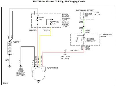
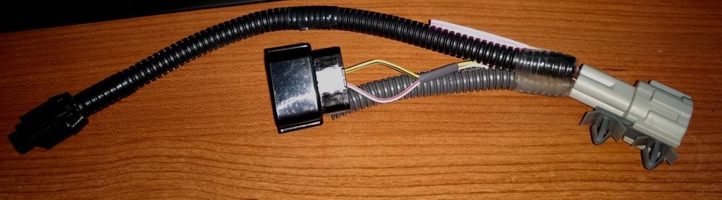
Looking at the directions for the alternator, the photo tells me a lot. The blue wire with the ring terminal is the one that will create the magnetic field to make the alternator work. In the Nissan wire harness, this is the yellow/black stripe wire. You could connect the blue wire as the directions state or splice it to the Nissan wire. Your call.
The yellow wire in the DC Power alternator connector is for the battery idiot light in the dash. In the Nissan wire harness for the 99 it is a white/red stripe wire. Once again, you could splice these wires together or not. This wire is not necessary for the alternator to work. It is only for the idiot light in the dash. If you don't splice the wires together, the light will never come on.
And when I say splice a wire, I mean solder them together. Both twist connectors and crimp connectors will develop corrosion and the electrical connection is lost.
Personally, I would do both splices. If you ever have to remove the alternator, it will be a tiny bit easier.
I would do what Dennis suggests, solder the wires from the Nissan harness to the DC alternator harness, DC Blue wire to Nissan Yellow/Black, DC Yellow wire to Nissan White/Red, hook it up, take it for a drive, and then call it a day.
Forgot to add the other instructions but they might help you figure it out. Was a bit confusing to me
If you solder the alternator's yellow wire to the Nissan's white/red stripe wire, you do not have to add a resistor. Nissan already has one built in. It is on the instrument cluster's printed circuit board.
Looking at the directions for the alternator, the photo tells me a lot. The blue wire with the ring terminal is the one that will create the magnetic field to make the alternator work. In the Nissan wire harness, this is the yellow/black stripe wire. You could connect the blue wire as the directions state or splice it to the Nissan wire. Your call.
The yellow wire in the DC Power alternator connector is for the battery idiot light in the dash. In the Nissan wire harness for the 99 it is a white/red stripe wire. Once again, you could splice these wires together or not. This wire is not necessary for the alternator to work. It is only for the idiot light in the dash. If you don't splice the wires together, the light will never come on.
And when I say splice a wire, I mean solder them together. Both twist connectors and crimp connectors will develop corrosion and the electrical connection is lost.
Personally, I would do both splices. If you ever have to remove the alternator, it will be a tiny bit easier.
Sorry missed your post
Seems legit im going to try splicng them together
But if i werent to splice them how is the alternator itself getting power for the electromagnet, through the blue wire on the alternator terminal directly from the battery?
Thank you both for your help its greatly appreciated im hoping to get it done today and let you know how it goes...its a bit snowy here in jersey right now
This alternator was made to order, i believe it is specifically for this car but the socket on the new alternator has 3 pins
The alternator case is made to match the Nissan (made by Hitachi) alternator so it will fit on the engine. As for the plastic connector, they can use whatever size/shape connector they want, have on hand or can buy for cheap. There is no requirement to use every possible wire opening. As I said earlier, only one wire is needed to make the alternator work, anything else is optional.
But if i werent to splice them how is the alternator itself getting power for the electromagnet, through the blue wire on the alternator terminal directly from the battery?
Only that blue wire is needed by the alternator. The DC Power people put a ring terminal so you can connect it to the output terminal of the alternator which is connected to the car's battery. They show that in the directions.
All wired up .. No more warning lights
everything seemed good car started as usual ran fine ....but was only reading 12 volts from the alternator and the battery... As if it wasnt charging.
i tested the wipers and they were extremely sluggish at full speed. So obviously theres a problem somewhere. Id hate to immediately assume the alternators no good.
anyone have any thoughts? Gonna do some troubleshoothing so ill be on here
Doesn't look good for the alternator. Call the alternator people and see what they say about some secret trick like is there a pin holding the brushes that needs to be removed.
Maybe im not getting the 12 volts from the
white/red to the yellow on the alternator . im thinking it needs to recieve power from this to allow the alternator to start...gonna go outside and check the white/red wire with the key turned .
Can anyone confirm if the. Battery light on the dash is supposed to light up with all other warning lights when key is turned..
I just noticed that mine does not
My battery light comes on when I turn the switch to the "on" position.
Thank you for confirming....mine does not.....
which from my understanding is necessary to complete the circuit on the alternator and allow it to start....
Which i believe is why if i werent to use the idiot light they say to wire it to a "key on" circuit. To give it power.....
so im assuming since the bulbs not lighting im probably not getting the 12 volts to white/ red wire at the alternator when i turn the key to on
Sound plausible ?. Guess i should go out and check but can anyone give me an idea why the bulb may not light when i turn key to on? ( bulb blown, fuse blown, ?)
The battery light circuit has nothing to do with the alternator working. As the instructions from the alternator people stated, the yellow wire that connects to the idiot light is optional to connect. While the white/red stripe wire should have 12 volts on it when the ignition key is in the ON position because that is the way Nissan designed it, it isn't needed to make the alternator produce current.
The other Nissan wire, the yellow/black stripe wire should have 12 volts to it all the time. This is the wire that you spliced to the alternator's blue wire. But since you have also connected the blue wire directly to the output terminal of the alternator and you still didn't get the alternator to work, there is probably something wrong with the alternator.
However, as a sanity check, measure for voltage at the alternator's output terminal where you connect the thick wire that goes to the battery. If you don't have 12 volts, the main fusible link (120 amp) could have somehow gotten blown.
im getting 12 volts at the alternator.
The battery FL is good.
ill be on the phone tomorrow
Thanks for the input
Alright so huge disappointment with the new alternator so far, for $600 you would think you would get something and not have any hassle .
So the old alternators back in the car running as it was , the new alternators back in the box ready to go back. I will give it another shot , **** happens , hopefully its a simple fix and they can get it back to me by the beginning of next week.
If it comes back defective again its going back for good and im pulling the amps and subs out.
You got my sympathies. What should be a fairly simple and straightforward job turned into a pile of dung for you. I hope that when you get the unit back, it will go in as it should.
Could you please help me. the wires broke off at the alt plug when replacing my alternator. I fixed the plug but can't figure out which wire goes to which sidr of the plug. There are 2 wires 1 brown and 1 yellow with black stripe. Please help if you can. Thank you. 2004 Nissan Murano SL 3.5
I take it you still have your alternator wiring harness to adapt for the new alternator?
my car wont run it ran yesterday and now doesn�t the long wire on that harness is not connected to anything I�m trying to figure out where it goes too any help would be appreciated
my car wont run it ran yesterday and now doesn�t the long wire on that harness is not connected to anything I�m trying to figure out where it goes too any help would be appreciated
That wire connects to three things: the wiring harness in the engine bay, the alternator, and the AC compressor.
I have an autotech 320 ho alt. But im charging at 14.7v to 14.8 simetimes stay at 14.6. But i deleted my engine batt plus i have 160ah yinlongs i found the pigtail but i cant find the sense wire or 12v The plug is under need
I have an autotech 320 ho alt. But im charging at 14.7v to 14.8 simetimes stay at 14.6. But i deleted my engine batt plus i have 160ah yinlongs i found the pigtail but i cant find the sense wire or 12v The plug is under need
1. wrong year. based on that radiator cap setup you have an 09+
2. no sense wire on the 09+. its a computer controlled alternator with varying voltage output based on demand.


 What should be a fairly simple and straightforward job turned into a pile of dung for you. I hope that when you get the unit back, it will go in as it should.


