Unanswered questions about DIY ambient footwell lighting w/ headlights.


 07-25-2010, 12:04 PM
#42
 07-25-2010, 04:26 PM
#43
Senior Member

Join Date: May 2008
Location: Moore, OK
Posts: 1,767
According to my remote starter/alarm install sheets, the courtesy lights (door trigger), the wire should be red w/white trace, or a light blue going into the SECU.
 07-25-2010, 04:32 PM
#44
I've got all my info. Now it's time to hook up some lights are see what's what. I'm not exactly rushing into this thing, but I'll remember to follow up with wiring confirmation when I get into it.
07-25-2010, 06:07 PM
#45
Junior Member
Thread Starter

Join Date: Jun 2010
Location: Northern NJ
Posts: 81
Rochester, the wires on the lights themselves are a good 18 inches at least, I used some 18 gauge stranded wire as well and spliced/soldered everything. Definitely post pictures and details of your courtesy lights adventure, as I am very interested.
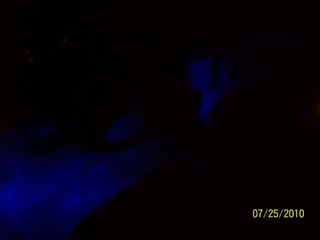
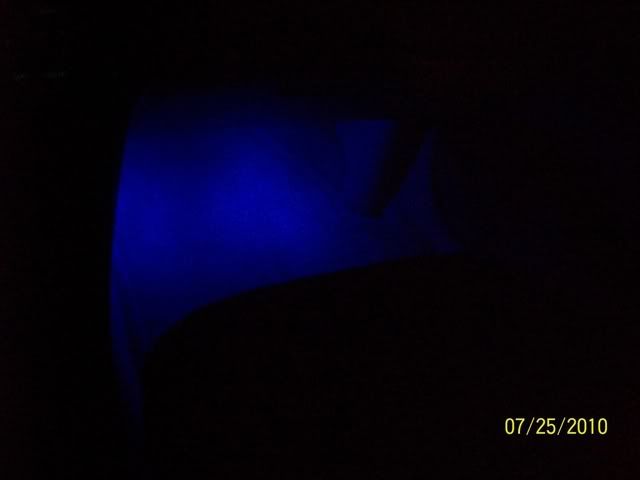
Pictures came out pretty good...
Pictures came out pretty good...
Last edited by dan.worts; 07-25-2010 at 07:11 PM.
 ) how are the pictures?
07-27-2010, 09:39 AM
) how are the pictures?
07-27-2010, 09:39 AM
#47
It's a really difficult task to take a picture intending to show how something is illuminated. In these pictures the color is much better represented, even though they're still primarily black images.
I'm going for white, myself, so it should look different than this. Just a dim, white LED light. I'll do what I can to photograph the results when I get to the mod. I haven't purchased lights yet, and just yesterday ordered a set of Posi-Tap connectors for the project:
http://www.posi-lock.com/posiplug.html
My plan is to first get the appropriate power/ground wiring established. After which, I can play with various lights and positions.
08-08-2010, 11:44 AM
#49
I don't think the #32 wire red w/white strips is the correct place to tap, because I got nothing.
Kind of frustrated right about now.
08-08-2010, 01:26 PM
#50

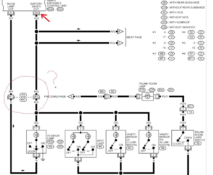
Hmmm, damn SECU makes things complicated. The battery Saver output for all the interior lamps is #50 which is red green. try that one, as it looks like power comes out of 50 goes to the step lamps and the circuit continues through to #32. Looks like I read it backward.
08-08-2010, 05:55 PM
#51
Hmmm, damn SECU makes things complicated. The battery Saver output for all the interior lamps is #50 which is red green. try that one, as it looks like power comes out of 50 goes to the step lamps and the circuit continues through to #32. Looks like I read it backward.
I'm not running out to the garage just now to continue experimenting, however. Wedging my upper torso underneath the drivers dashboard, upside down, is a damn uncomfortable feat for these old bones.
Anyway, when I get this going again, here are the LED's I got through ebay for like $3/pair. Each strip has an adhesive backing, and should work out well enough hidden in the foot-wells. We'll see.

 08-15-2010, 10:53 AM
#53
Hmmm, damn SECU makes things complicated. The battery Saver output for all the interior lamps is #50 which is red green. try that one, as it looks like power comes out of 50 goes to the step lamps and the circuit continues through to #32. Looks like I read it backward.

When connected to the red w/green striped #50 wire on the 2-row harness, the power is constant, regardless of whether or not the door is open. In other words, this is a fine wire for direct, always-on power. But like you, I'm going for lighting in sync with the courtesy (door) lights.
Any other suggestions? There are 64 wires down there...
08-15-2010, 01:09 PM
#54
#30 is the keyhole illumination and 32 are the step lamps for sure.
The driver's door switch ground is #1. So when the door is open #1 has ground , when the door is closed there is no ground. That might work for you.
Now if you want them to fade like the keyhole does, then positive is 30 and ground is number one, or if you want them off immediately after closing the door 32 is the power.
08-15-2010, 01:39 PM
#55
#30 is the keyhole illumination and 32 are the step lamps for sure.
The driver's door switch ground is #1. So when the door is open #1 has ground , when the door is closed there is no ground. That might work for you.
Now if you want them to fade like the keyhole does, then positive is 30 and ground is number one, or if you want them off immediately after closing the door 32 is the power.
The driver's door switch ground is #1. So when the door is open #1 has ground , when the door is closed there is no ground. That might work for you.
Now if you want them to fade like the keyhole does, then positive is 30 and ground is number one, or if you want them off immediately after closing the door 32 is the power.
So far, we've tried:
P32, G43 - nothing
P50, G43 - always on
 08-15-2010, 05:46 PM
#57
Junior Member
Thread Starter
Join Date: Jun 2010
Location: Northern NJ
Posts: 81
 08-15-2010, 06:56 PM
#58
08-15-2010, 07:59 PM
#59
Try 30 or 32 for positive. And 1 for the ground
Personally I think P30 G1 would look best because they would fade slowly instead of turning right off when the door closes.
Personally I think P30 G1 would look best because they would fade slowly instead of turning right off when the door closes.
Last edited by knight_yyz; 08-16-2010 at 07:20 AM.
08-21-2010, 02:33 PM
#60
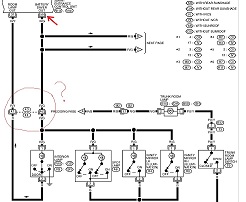
Had this moment when I went to tackle this again today. I've been looking at each of the 3 wire-bundle connectors to establish which wire is which. But then I got all turned around wondering if these wires are identified by looking at the side with all the wires, or the side with all the holes...
...and I got all stupid confused.
So I went back to this post for clarification. Please confirm (anyone) that the diagram represents looking directly at the large plastic harness. From that, you can draw a mental line to the bundle connector matching hole. And from that, the wire on the other wide.
09-18-2010, 02:04 PM
#62
Newbie - Just Registered

Join Date: Sep 2010
Posts: 8
I'm going to be doing this mod to my 2001 I30, but I'm curious about the wiring. Is there any way to make sure that the wire I'm about to splice in to will do the trick without actually slicing into it?
Also, is the dome light part of this circuit? I mean, if I have the dome light turned off will the new lights still power on? That would be ideal, I think. Have the LEDs and the courtesy lights come on, and then the LEDs fade out when the doors close, but still have the dome light connected in case it's needed.
Also, is the dome light part of this circuit? I mean, if I have the dome light turned off will the new lights still power on? That would be ideal, I think. Have the LEDs and the courtesy lights come on, and then the LEDs fade out when the doors close, but still have the dome light connected in case it's needed.
09-18-2010, 02:33 PM
#63

Another solution if no one has considered this, is wiring your parking lights to come on anytime a door in opened. For those with aftermarket alarms its very simple since the needed wires are already there. Power, door trigger and parking lamp wires are all thats needed.
Using a relay its simple. Since my parking lights and lights beneath the dash are connected they come on whenever the door is opened.
Using a relay its simple. Since my parking lights and lights beneath the dash are connected they come on whenever the door is opened.
09-18-2010, 10:22 PM
#64
Newbie - Just Registered
Join Date: Sep 2010
Posts: 8
Another solution if no one has considered this, is wiring your parking lights to come on anytime a door in opened. For those with aftermarket alarms its very simple since the needed wires are already there. Power, door trigger and parking lamp wires are all thats needed.
Using a relay its simple. Since my parking lights and lights beneath the dash are connected they come on whenever the door is opened.
Using a relay its simple. Since my parking lights and lights beneath the dash are connected they come on whenever the door is opened.

I wish I could find a good guide to the car's wiring somewhere. One central resource that said "the red wire with the thin green strip that is connected here is the wire for blank". All I can find are schematics and wiring diagrams that tell me what a particular devices is connected to, just not the details.
 09-18-2010, 10:24 PM
#65
Well the dome lights run in the a pillar....
http://forums.maxima.org/5th-generat...s-diy-how.html
done
http://forums.maxima.org/5th-generat...s-diy-how.html
done
09-20-2010, 07:42 PM
#66
Newbie - Just Registered
Join Date: Sep 2010
Posts: 8
Ok, looking at page 127 of the EL section of the 2001 Infiniti I30 service manual, it looks like the connection would be 50+ and 31 ground.
(Click for larger view)
This is based on what the manual says a few pages beforehand:
When a signal, or combination of signals is received by the smart entrance control unit, ground is supplied:
- through smart entrance control unit terminal 31
- to interior lamp terminal 2.
With power and ground supplied, the interior lamp illuminates.
Plus, because I popped off the dome light cover and saw the color of one of the cables was Red/Green, so I think I'm half right.
Unless I'm not reading the diagrams right....which is a good possibility.

Thread
Thread Starter
Forum
Replies
Last Post
Slamrod
4th Generation Maxima (1995-1999)
5
04-10-2016 05:24 PM
Dennis Twohy
1st & 2nd Generation Maxima (1981-1984 and 1985-1988)
0
10-01-2015 06:01 PM
rbaker100
8th Generation Maxima (2016-)
9
08-28-2015 08:11 PM