
Blower motor resistor - Take Two...


Blower motor resistor - Take Two...
Long story short...
...resistor blew out back in late 2006. Pulled resistor and resoldered the crossover. Re-installed. Fixed!
Fast forward to yesterday.
Resistor blew again. Pulled resistor, noticed the solder had come loose. Resoldered the crossover with small piece of telephone wire. Reinstalled. Fixed!
Hopefully this will get me another 4 years
Much cheaper alternative than buying new one.
Last edited by nismopc; Jul 28, 2010 at 09:16 AM.


Long story short...
...resistor blew out back in late 2006. Pulled resistor and resoldered the crossover. Re-installed. Fixed!
Fast forward to yesterday.
Resistor blew again. Pulled resistor, noticed the solder had come loose. Resoldered the crossover with small piece of telephone wire. Reinstalled. Fixed!
Hopefully this will get me another 4 years
Much cheaper alternative than buying new one.
...resistor blew out back in late 2006. Pulled resistor and resoldered the crossover. Re-installed. Fixed!
Fast forward to yesterday.
Resistor blew again. Pulled resistor, noticed the solder had come loose. Resoldered the crossover with small piece of telephone wire. Reinstalled. Fixed!
Hopefully this will get me another 4 years
Much cheaper alternative than buying new one.
Simple fix.
Remove plug from resistor. Remove two philips screws holding resistor in place.
Once you pull the resistor out, you will see exactly where to solder. There is a long winding circuit on the board that apparently creates the varying resistance (speeds).
To the center right side of the board, you will see a larger portion where the "resistor" portion most likely burned. It is there that you just solder a new wire across the two contacts.
Works perfectly!

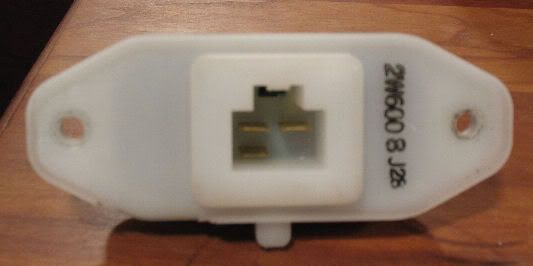
You make it sound nice and easy, but I guess I will need a bit more of a visual to determine just where you are soldering in this piece of wire. I have taken a picture of my resistor assuming this is the one you are describing.
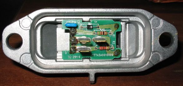
and this picture is with the plastic casing removed exposing the circuit board, so can you point me a bit better in the direction of just where you are soldering.
and this picture is with the plastic casing removed exposing the circuit board, so can you point me a bit better in the direction of just where you are soldering.
Last edited by Ghost_54; Jul 28, 2010 at 08:55 PM.
I will make the assumption that you have electronic HVAC controls not manual. The part you took a picture of is called a "Fan Control Amplifier". The one I have is a "Blower Motor Resistor"
The resistor is completely different than yours. Sorry...
The resistor is completely different than yours. Sorry...
Last edited by nismopc; Jul 30, 2010 at 09:11 AM.
Yes I have the digital HVAC, thanks for clearing that up as the two modules are very different ... didn't hurt to ask and see if I was on the same page as you.
Thanks for the reply
Thanks for the reply

Newbie - Just Registered
Joined: Jun 2007
Posts: 6
You make it sound nice and easy, but I guess I will need a bit more of a visual to determine just where you are soldering in this piece of wire. I have taken a picture of my resistor assuming this is the one you are describing.
and this picture is with the plastic casing removed exposing the circuit board, so can you point me a bit better in the direction of just where you are soldering.
and this picture is with the plastic casing removed exposing the circuit board, so can you point me a bit better in the direction of just where you are soldering.
What ever came from this? I think I have the same problem - my circuit board is identical to yours. To me, it looks like the circuit on the far right of the panel is blown, but I am not an expert. Can anyone else confirm based on the picture if the panel is blown or not?

From that bottom photo, nothing looks blown. What you see on both the left and right side is the flux residue from the soldering process.
On this module (called the Fan Control Amplifier) for the auto climate control, the most common failure is the transistor hidden on the other side of the printed circuit board. The 3 solder spots on the left side of the printed circuit board are the transistor connections. A couple of years ago I tried to find a replacement transistor and failed. Nobody listed the transistor number.
There is a org member named Maxima_Joe who sells used parts for 4th gen Maximas. PM him, maybe he also sells 5th gen parts too. Otherwise it's the dealer or junkyard.
Newbie - Just Registered
Joined: Jun 2007
Posts: 6
From that bottom photo, nothing looks blown. What you see on both the left and right side is the flux residue from the soldering process.
On this module (called the Fan Control Amplifier) for the auto climate control, the most common failure is the transistor hidden on the other side of the printed circuit board. The 3 solder spots on the left side of the printed circuit board are the transistor connections. A couple of years ago I tried to find a replacement transistor and failed. Nobody listed the transistor number.
There is a org member named Maxima_Joe who sells used parts for 4th gen Maximas. PM him, maybe he also sells 5th gen parts too. Otherwise it's the dealer or junkyard.
On this module (called the Fan Control Amplifier) for the auto climate control, the most common failure is the transistor hidden on the other side of the printed circuit board. The 3 solder spots on the left side of the printed circuit board are the transistor connections. A couple of years ago I tried to find a replacement transistor and failed. Nobody listed the transistor number.
There is a org member named Maxima_Joe who sells used parts for 4th gen Maximas. PM him, maybe he also sells 5th gen parts too. Otherwise it's the dealer or junkyard.
Thank you very much! I have PM'd Joe. In the meantime, would anyone have any advice on how to test the part to see if it is shot? Would a continuity test with a volt meter do the trick?
If the blower motor is always running on high speed, then the transistor is shorted, and must be replaced. Not even worth the time testing. But most of the time, this is not the problem.
Most of the time the transistor OPENs and you have no blower motor. You can check the transistor by measuring the base to emitter, base to collector and emitter to collector resistance, using both polarities. You can't get accurate readings while the transistor is soldered into the printed circuit board because of secondary circuits that are on the printed circuit board. Is this starting to sound like a pain in the butt? Well it is.
An easier way is to measure the voltage on one of the wires that plugs on to the fan control amplifier. It is the thin blue/yellow stripe wire. Have the connector plugged on and measure voltage from ground to the wire. Don't forget that the ignition key has to be in the ACC or ON position for the fan to work.
When the climate contol is off, there should be almost 0 volts in the wire. On low fan speed, 2.5 volts. as you increase the fan speed on the control panel, the voltage goes up: 2.9, 3.2, 8.2 volts for high speed.
The voltages may be a little bit different, but not dramatically.
Newbie - Just Registered
Joined: Jun 2007
Posts: 6
If the blower motor is always running on high speed, then the transistor is shorted, and must be replaced. Not even worth the time testing. But most of the time, this is not the problem.
Most of the time the transistor OPENs and you have no blower motor. You can check the transistor by measuring the base to emitter, base to collector and emitter to collector resistance, using both polarities. You can't get accurate readings while the transistor is soldered into the printed circuit board because of secondary circuits that are on the printed circuit board. Is this starting to sound like a pain in the butt? Well it is.
An easier way is to measure the voltage on one of the wires that plugs on to the fan control amplifier. It is the thin blue/yellow stripe wire. Have the connector plugged on and measure voltage from ground to the wire. Don't forget that the ignition key has to be in the ACC or ON position for the fan to work.
When the climate contol is off, there should be almost 0 volts in the wire. On low fan speed, 2.5 volts. as you increase the fan speed on the control panel, the voltage goes up: 2.9, 3.2, 8.2 volts for high speed.
The voltages may be a little bit different, but not dramatically.
Most of the time the transistor OPENs and you have no blower motor. You can check the transistor by measuring the base to emitter, base to collector and emitter to collector resistance, using both polarities. You can't get accurate readings while the transistor is soldered into the printed circuit board because of secondary circuits that are on the printed circuit board. Is this starting to sound like a pain in the butt? Well it is.
An easier way is to measure the voltage on one of the wires that plugs on to the fan control amplifier. It is the thin blue/yellow stripe wire. Have the connector plugged on and measure voltage from ground to the wire. Don't forget that the ignition key has to be in the ACC or ON position for the fan to work.
When the climate contol is off, there should be almost 0 volts in the wire. On low fan speed, 2.5 volts. as you increase the fan speed on the control panel, the voltage goes up: 2.9, 3.2, 8.2 volts for high speed.
The voltages may be a little bit different, but not dramatically.

Thread
Thread Starter
Forum
Replies
Last Post
AaronL
5th Generation Maxima (2000-2003)
15
Aug 8, 2020 10:31 AM
Unclejunebug
5th Generation Maxima (2000-2003)
10
Apr 2, 2016 05:42 AM
CAN-Toronto FS: Basement cleaning
knight_yyz
5th Generation Classifieds (2000-2003)
12
Nov 1, 2015 01:34 PM