
Cattman header install...


I was looking at Datsun's pics and only ONE of the holes on mine is too close to the edge...all the other holes seemed cool. Looking at his, I think I saw at least 4 that were off and close to the edge....wow....that's not cool man.
@DATSUN.....did you have any trouble connecting the ypipe to the headers or did they go on as planned?
I'm really surprised Brian has not come on to this forum other than that one time.....he was all over that forum with the new company making 3" catback exhaust......
Last edited by ranmas2004; Jun 12, 2011 at 07:58 PM.


Junior Member
Joined: Mar 2011
Posts: 16
From: NW Indiana
^^I've had no name ebay headers for 2+years without issue as well. However, the flanges on the ebay y-pipe needed to be modified b/c they did not line up to the flanges on the headers correctly.
You guys are not alone with this Cattman issue. I know of at least two Altima guys that had the exact same problem with the holes in the flanges not lining up with the studs correctly and needing to be drilled out.
You guys are not alone with this Cattman issue. I know of at least two Altima guys that had the exact same problem with the holes in the flanges not lining up with the studs correctly and needing to be drilled out.

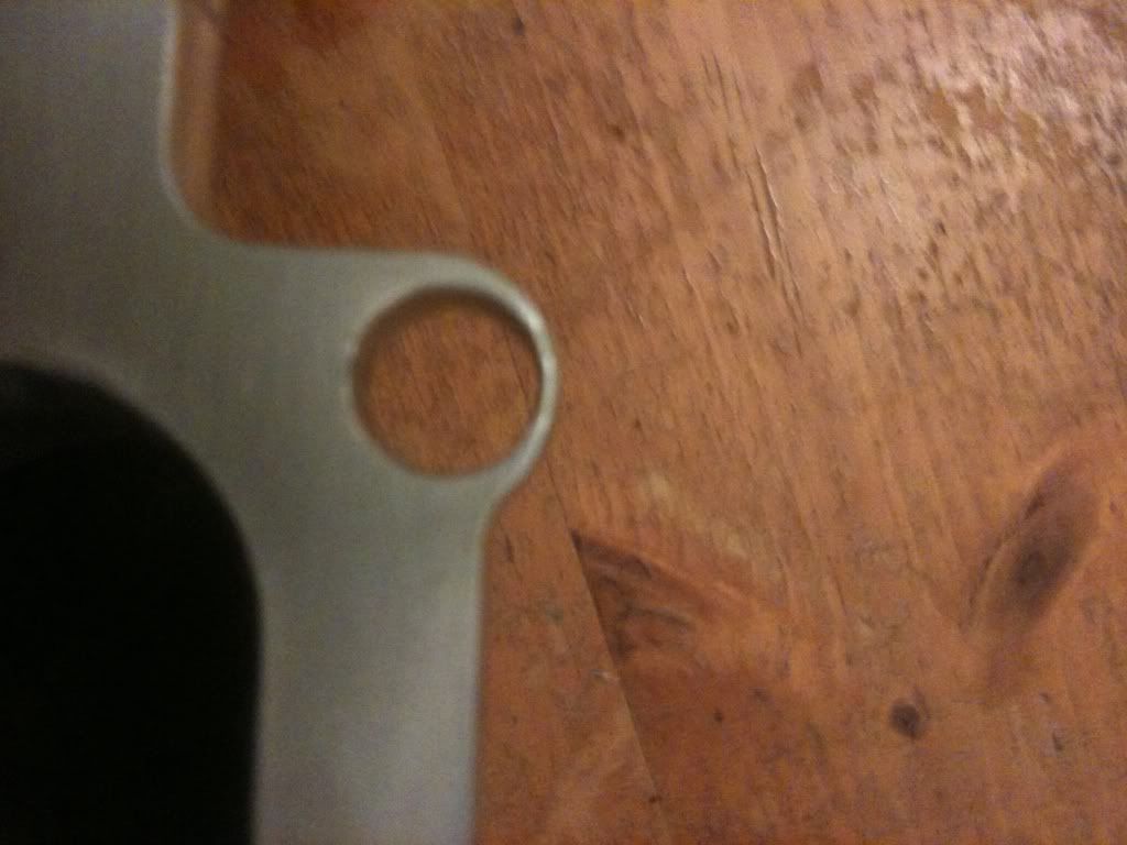
I tried to install my Cattmans on my 2K2 last night . On the radiator side it appears the holes On the head flange were drilled improperly ? These pictures show how close one hole is to the edge of the flange. I didn't measure it but it appears to be a 1/16 inch of thickness between the hole and the end of the flange.
Did andy one else have any issues installing their's???
Did andy one else have any issues installing their's???

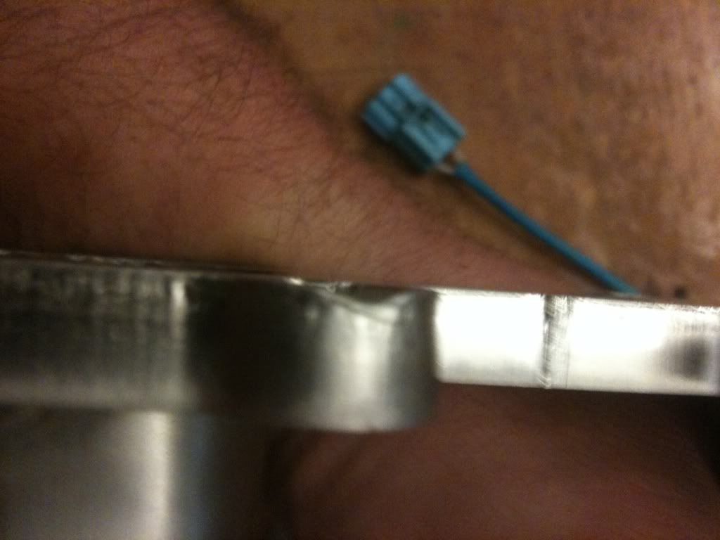
Yes they fit once I reamed them out with a drill bit and my dremmel . Alot of going back and forth test fitting them . I just got finished with them today I had to extend the primary O2 wires .
I had no choice I had to get them on . I need my car and it sitting waiting for a solution wasn't a option for me.
I had no choice I had to get them on . I need my car and it sitting waiting for a solution wasn't a option for me.
I just got a set of Cattman headers are well. I will try to fit them on the heads I have when I get home.
EDIT
So I checked and sure enough, neither header would slide over the studs and mount to the head. The holes seems to be too far towards the edge of the flange. Kinda sucks for something that costs almost a thousand dollars. I bought these because I wanted superior fitment.
EDIT
So I checked and sure enough, neither header would slide over the studs and mount to the head. The holes seems to be too far towards the edge of the flange. Kinda sucks for something that costs almost a thousand dollars. I bought these because I wanted superior fitment.
I looked close last night and the holes on mine are really close to the edges too. I won't get around to installing them for a few weeks but I hope there are no issues. Like ajm8127 said, fitment issues are unacceptable for something that costs this much but fingers crossed that there will be no problems.
Again OBX wish it had just a flange bolt hole off.....they really wish it was their only issue!!!!!
Cool!!! I saw them, now flip the gasket and try it all 4 ways and show the complete gasket and all the ports/bolt holes next time
If that's the case hopefully not!
Last edited by CMax03; Jun 13, 2011 at 12:03 AM.


I am a part of this new batch, but have not installed them yet. I will check them when I get home from work today to see where the holes are.
Silly questions, but I assume you tried installing them on the correct side? Also, is there perhaps a measurement difference between the 2000 and 2003 engines?
Silly questions, but I assume you tried installing them on the correct side? Also, is there perhaps a measurement difference between the 2000 and 2003 engines?

Yes, I mounted them on the CORRECT side . If you try to mount the rear header on the front it hits the motor mount bracket so there is NO way I installed these incorrectly ....
Last edited by datsunzcar84; Jun 13, 2011 at 05:10 AM.

For sure, that's what I plan to do, it's just annoying. C'est la vie

Seems like widening the holes is going to be the lesser of two evils. I would rather not send my headers back and wait another 3 months to be fixed. I feel like there needs to be some form of reimbursement for our troubles tho (maybe free shipping if/when we place another order) idk
Last edited by rosader; Jun 13, 2011 at 07:39 AM.

I'm looking into this, but there is only one set of possibly useful pictures here, by ranmas2003. Except, only about 10% of the pictures download. I've copied the links and into new windows, and only the top slice appears (except for the first image), so I'm wondering if the loaded up all the way in the first place.
If someone can do it, the most useful picture - something I can take straight to my exhaust partner to figure this out - would be a picture of the entire head flange with the gasket overlaid. Putting a bolt through a hole at one end of the flange will "anchor" the position so we can see how far its off at the opposite end.
This is the only way to tell if something's off. It is absolutely impossible to simply eyeball two different (new and older) header pictures and say that the holes in one are too far over relative to the other one, because the actual outline of the flange is different. Since the two flange outlines are slightly different, there will be differences in the thickness of the metal around the hole, even if the holes are in identical positions.
I'll be working with my exhaust partner this week to find the best solution to this, but having pictures that accurately reference the problem is the critical first step. Sorry I have to rely on you guys to do this, but since the headers have left my hands, and a number of you have gasket sets, that's my only option.
To reiterate though, I have no clue if I have a "problem" set or not as I have not tried to install them yet.
BTW, let's not turn this into a bash Brian/Cattman thread. He has been making quality pieces for our cars for a LONG time. YES, it is disappointing that it does not fit perfectly out of the box. Brian is a stand up a guy and I am sure one we get to the bottom of this, that he will make it right.

Junior Member
Joined: May 2011
Posts: 0
From: Madison WI
I had the same problem with mine. I had to drill out the holes to make them fit over the studs for the exhaust. Also had to cut the metal piece going over the rear MM to get them to go in by the firewall. Still waiting on the front header atm. I also had to extend the primary o2 sensors, which isn't that big of a deal.
let's not turn this into a bash Brian/Cattman thread. He has been making quality pieces for our cars for a LONG time. YES, it is disappointing that it does not fit perfectly out of the box. Brian is a stand up a guy and I am sure one we get to the bottom of this, that he will make it right.
Not the core topic of this thread, but I'll mention that it shouldn’t be necessary to extend the sensor wires. My mechanic has always been able to free up enough wire to make this work without a splice.
Brian
Brian

I had the same problem with mine. I had to drill out the holes to make them fit over the studs for the exhaust. Also had to cut the metal piece going over the rear MM to get them to go in by the firewall. Still waiting on the front header atm. I also had to extend the primary o2 sensors, which isn't that big of a deal.


As soon as I can I will be removing the manifold off of my new engine that is out on my deck and test fit these and take pics as well against the gasket set from brian.
I too have faith in Brian. Still the superior product. Things go wrong some times with anything. I much rather have Brian the guy to fix an issue like this over some ebay seller of OBX.
I too have faith in Brian. Still the superior product. Things go wrong some times with anything. I much rather have Brian the guy to fix an issue like this over some ebay seller of OBX.
Realizing that the bolt holes in the gaskets are somewhat oversized, the PERFECT way for me to determine what is off, and by how much, would be to take pics showing how the studs match up with the holes.
Even if they won't slip on, get one stud a little ways through a hole at one end of the flange to provide a fixed reference point, and then take pictures that show where the rest of the studs are relative to the other holes.
Of course you can feel free to post here, but please get that information to me directly as soon as possible because that's what I need to show my exhaust partner in order to figure out what sort of solution is necessary.
Brian
As soon as I can I will be removing the manifold off of my new engine that is out on my deck and test fit these and take pics as well against the gasket set from brian.
I too have faith in Brian. Still the superior product. Things go wrong some times with anything. I much rather have Brian the guy to fix an issue like this over some ebay seller of OBX.
I too have faith in Brian. Still the superior product. Things go wrong some times with anything. I much rather have Brian the guy to fix an issue like this over some ebay seller of OBX.
 Let me know if I screwed up the pics somehow (didn't put the gasket on correctly, or whatever).


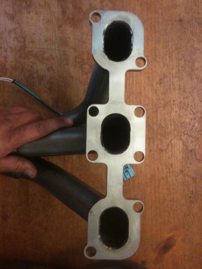
Something that concerned me while looking at these where the exhaust ports. They don't exactly have a "perfect" oval shape and almost look like they are prepped for some exhaust leakage. Not sure if this is normal or not?


Thanks for more photos. I promise to try to get to mine soon. If I could get my engine on the engine stand tonight it would work out well.
+1
Has previous batches and previous versions been jagged non ovaled the same way?
Is it possible the people who had success with this batch got the maybe left over flanges made by the previous partner of Brian?
+1
Has previous batches and previous versions been jagged non ovaled the same way?
Is it possible the people who had success with this batch got the maybe left over flanges made by the previous partner of Brian?
Last edited by NmexMAX; Jun 13, 2011 at 01:35 PM.
Junior Member
Joined: Mar 2011
Posts: 16
From: NW Indiana
Looking at those pics makes me wonder why they are welded on the INSIDE of the flanges. Welding them on the outside should be sufficient, no? (please correct me if I'm wrong) And it would give a clean, even surface for the flange. I can't say I've ever seen headers welded on the inside like that (including the older Cattman's, were they?).
That being said, the welds look really good, maybe they should have been a little farther down into the flange, though b/c it does look like when some of them penetrated into the flange, it distorted the exhaust port a little.
That being said, the welds look really good, maybe they should have been a little farther down into the flange, though b/c it does look like when some of them penetrated into the flange, it distorted the exhaust port a little.
Last edited by altjt02; Jun 13, 2011 at 12:51 PM.
Junior Member
Joined: May 2011
Posts: 0
From: Madison WI
It may just be because its in an Altima and not a Max, not sure lol.
Here's a pic of the think metal part of the motor mount that I had to cut off for the headers to fit. It isn't part of the actual bracket piece of the motor mountm it just was a thin layer of metal that went over the mount itself, but was connected to it.

as far as extending the o2 wires, I didn't really try to make the rear primary o2 sensor fit since it didn't look like to me that it would if i tried. So i didn't bother, not like it is that hard anyway so it isnt a prob.
Here's a pic of the think metal part of the motor mount that I had to cut off for the headers to fit. It isn't part of the actual bracket piece of the motor mountm it just was a thin layer of metal that went over the mount itself, but was connected to it.
as far as extending the o2 wires, I didn't really try to make the rear primary o2 sensor fit since it didn't look like to me that it would if i tried. So i didn't bother, not like it is that hard anyway so it isnt a prob.
Looking at those pics makes me wonder why they are welded on the INSIDE of the flanges. Welding them on the outside should be sufficient, no? (please correct me if I'm wrong) And it would give a clean, even surface for the flange. I can't say I've ever seen headers welded on the inside like that (including the older Cattman's, were they?).
That being said, the welds look really good, maybe they should have been a little farther down into the flange, though b/c it does look like when some of them penetrated into the flange, it distorted the exhaust port a little.
That being said, the welds look really good, maybe they should have been a little farther down into the flange, though b/c it does look like when some of them penetrated into the flange, it distorted the exhaust port a little.
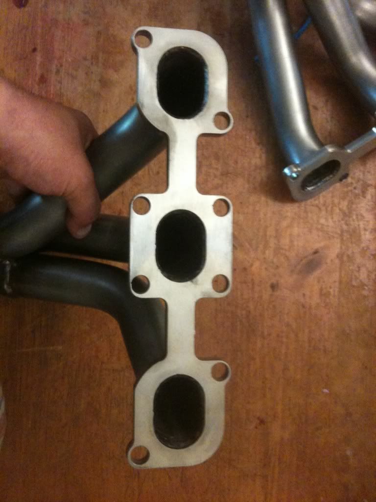
The only issue with these pics is that the gasket hole with the bolt through it needs to be centered over the bolt hole. There has to be at least one reference hole where the two holes are centered over each other. Then you can tell how it fits the others.
See how the gasket hole (with the bolt in it) is offset over the flange hole?

Let's try again, setting the picture up like I've illustrated below:

The two holes I indicate are not sloppy large in the gasket, they're about the same size as the holes in the flange. Put bolts or pins through both, and it will position the gasket squarely on the flange. Might be useful to tape the gasket to the flange once that's all lined up so it doesn't move around. Take pictures of the whole flange, and closeup pictures of any holes that seem to be off.
Might seem like a lot of hassle, but this is exactly how I would do it, if the parts were in front of me. Nothing less will really give us the perspective we need to determine exactly what is not right.
Brian
See how the gasket hole (with the bolt in it) is offset over the flange hole?
Let's try again, setting the picture up like I've illustrated below:
The two holes I indicate are not sloppy large in the gasket, they're about the same size as the holes in the flange. Put bolts or pins through both, and it will position the gasket squarely on the flange. Might be useful to tape the gasket to the flange once that's all lined up so it doesn't move around. Take pictures of the whole flange, and closeup pictures of any holes that seem to be off.
Might seem like a lot of hassle, but this is exactly how I would do it, if the parts were in front of me. Nothing less will really give us the perspective we need to determine exactly what is not right.
Brian


The pictures are exactly what I was looking for, thanks. Well, its not off by much, no wonder they could be modified with home tools. If the hole's 1/4" off there usually isn't anything sitting around the garage that can take off that much steel.
Some of the holes match up, and the others are barely off, so close that they fit on some cars and not others, which means perhaps 1-2 hundredths of an inch or even less. There is no "almost" with steel unless you use a hammer, and we discourage that method.
Of course I'm thinking in terms of what could have gone wrong, and it might be that the mistake was making the holes slightly too small, rather then putting them in the wrong places, because even though these flanges were made by a different company, they're still made using the same CNC programming. Even though the CNC mill is following the same pattern, the parts won't be 100% identical due to slight differences in tooling, or the age of the machine and how tight the tolerances are.
As far as welding goes, those are excellent scalloped TIG welds and its all done exactly the way it should be on both sides. That fabrication method takes a lot longer (i.e. more expensive), but it is one of many subtle features a trained eye will recognize in our parts. To sum it up in a sentence, not only is there is absolutely nothing to criticize about it, this is a fabrication feature that is desirable and found on very few production header sets. Here's why I think its worthwhile...
TIG-welding on the inside as we do is very strong and it creates a smoothed lip instead of just the raw edge of the tubing that creates a ledge with a gap underneath right in the face of the onrushing exhaust gasses coming out of the heads. The end/edge of the tube can't be made flush with the perimeter of the port without welding or a large press or forge with a die that press-forms the tube to the inside of the ports - farther down the exhaust it doesn't matter as much, but here it needs to be smooth without that tubing ledge causing turbulence. The thick welds on the back are for added strength but there's no reason to weld all the way around when its already done on the inside.
Finally, my intent is to make arrangements for sending back manifolds for those who need to have us drill out the holes enough to avoid any fitment issues. I have to communicate with my exhaust partner first, and after I work out the protocol with him, I'll report back to this thread. I will also offer some kind of consideration to those who were inconvenienced, but let me give this some thought and see what my exhaust partner will be doing.
I will say this for those who'd like to get them on right away. If you're planning to have a competent mechanic in a real garage put these one, I really cannot imagine how this would be a show-stopper. No excuse for these Cattman Performance parts not fitting perfectly - I'd be the first to point that out - but compared with the exhaust parts that typically get carried into a shop for installation, they are still solid gold.
Tell the mechanic what to expect, and if the guy's capable and isn't just a robotic parts remover/replacer that goes into a tizzy if something's unexpected, then I can't see how it would be an issue. Everyone can see how close these are - so I shouldn't need to point out in advance that if someone ruins a header getting it on, its because they're a dumbsh!t, not because of this minor flaw. Its also not something that should take more than 10-15 minutes to deal with if its done systematically to minimize the # of holes that need adjustment.
Brian
Junior Member
Joined: Mar 2011
Posts: 16
From: NW Indiana
It may just be because its in an Altima and not a Max, not sure lol.
Here's a pic of the think metal part of the motor mount that I had to cut off for the headers to fit. It isn't part of the actual bracket piece of the motor mountm it just was a thin layer of metal that went over the mount itself, but was connected to it.
as far as extending the o2 wires, I didn't really try to make the rear primary o2 sensor fit since it didn't look like to me that it would if i tried. So i didn't bother, not like it is that hard anyway so it isnt a prob.
Junior Member
Joined: May 2011
Posts: 0
From: Madison WI

If you decide to modify your hole(s) a dremel would probably be best just mark those that need to be adjusted cause drilling them to the next sized bit may not be necessary when it's needing a slight elongation! Good luck guys! It's off be a red **** hair maybe, if you try to put these on with any slight angle they would go! The would mate up perfectly if flip over...The gasket holes are larger than the studs and some are elongated holes.....it's the angle of the dangle to make them fit! Reply #67 look fine to me....Opening the bores slightly with dremel is all that's needed guys......it's a minor adjustment!
Last edited by CMax03; Jun 13, 2011 at 10:33 PM.
As far as welding goes, those are excellent scalloped TIG welds and its all done exactly the way it should be on both sides. That fabrication method takes a lot longer (i.e. more expensive), but it is one of many subtle features a trained eye will recognize in our parts. To sum it up in a sentence, not only is there is absolutely nothing to criticize about it, this is a fabrication feature that is desirable and found on very few production header sets. Here's why I think its worthwhile...
TIG-welding on the inside as we do is very strong and it creates a smoothed lip instead of just the raw edge of the tubing that creates a ledge with a gap underneath right in the face of the onrushing exhaust gasses coming out of the heads. The end/edge of the tube can't be made flush with the perimeter of the port without welding or a large press or forge with a die that press-forms the tube to the inside of the ports - farther down the exhaust it doesn't matter as much, but here it needs to be smooth without that tubing ledge causing turbulence. The thick welds on the back are for added strength but there's no reason to weld all the way around when its already done on the inside.
Brian
Thanks again Brian!


So This is my engine that I will be installing. Granted it is from an 04 but that shouldnt matter as far as the header is concerned. The front manifold was a little rough going in but it went in clean and flush. The rear manifold does not make it. The problem lies with the middle lower bolt hole. It appears at it doesnt need much opening up the hole at all. The header actually makes it around the star portion of the stud but not the threaded area. I hope these pics help.
btw the pic that shows the header fully on is the front side. I have not done anything to the rear manifold to get it to fit. I will most likely be drilling or taking it somewhere to get drilled, the shipping will prob take to long and I honestly dont feel that it is necessary for any side of the party to spend so much on shipping for such a simple fix. Mine is barely off. Not sure about others. I would think the same defect would be with all.
So This is my engine that I will be installing. Granted it is from an 04 but that shouldnt matter as far as the header is concerned. The front manifold was a little rough going in but it went in clean and flush. The rear manifold does not make it. The problem lies with the middle lower bolt hole. It appears at it doesnt need much opening up the hole at all. The header actually makes it around the star portion of the stud but not the threaded area. I hope these pics help.