
direct fuse box grounds

This isn't working out well for you, Mr. Aviator. If a person walks into a room full of strangers and gets ragged on, it's entirely possible he walked into a room full of douchbags. But if he walks into another room, and it happens again, and then yet again...
...see where I'm going with this?
 True enough.
...see where I'm going with this?
True enough.

Thread Starter
Member
Joined: May 2011
Posts: 211
Also the chassis of the car itself has a very low resistance compared to wires because the entire body shell/frame of the car is a very "fat wire" of a conductor, so grounding something in the trunk (like an amp) to the body of the car will actually be a better ground than running a ground wire all the way from the amp (in the trunk) to the battery.
and i dont really mind people are hating, I know it works so i enjoy everyones reaction hahhah :P guess i am half troll
Last edited by Aviation005; Dec 11, 2012 at 08:45 PM.

Not to add fuel to the flames here, but why do you keep insisting that having TWO chassis grounds is so much MORE grounded than factory? Have you even cracked open the FSM just once? Might wanna go dust that off.
Factory Chassis Grounds
M9 - Just below driver's side A pillar
M25 - Just behind fuse box
M87 - Behind glove box
I'm glad you have TWO chassis grounds, I have THREE (3). Must be why my Maxima is so much faster than yours.

Factory Chassis Grounds
M9 - Just below driver's side A pillar
M25 - Just behind fuse box
M87 - Behind glove box
I'm glad you have TWO chassis grounds, I have THREE (3). Must be why my Maxima is so much faster than yours.
Last edited by rebelhell; Dec 11, 2012 at 08:53 PM.
Thread Starter
Member
Joined: May 2011
Posts: 211
Not to add fuel to the flames here, but why do you keep insisting that having TWO chassis grounds is so much MORE grounded than factory? Have you even cracked open the FSM just once? Might wanna go dust that off.
Factory Chassis Grounds
M9 - Just below driver's side A pillar
M25 - Just behind fuse box
M87 - Behind glove box
I'm glad you have TWO chassis grounds, I have THREE (3). Must be why my Maxima is so much faster than yours.
Factory Chassis Grounds
M9 - Just below driver's side A pillar
M25 - Just behind fuse box
M87 - Behind glove box
I'm glad you have TWO chassis grounds, I have THREE (3). Must be why my Maxima is so much faster than yours.
also because i have tried with (1) 4GA wire ground, then added another and had brighter dash lights and better performance
I have tried with just the stock 4GA factory ground, the dash was dim

I'm not sure why you think Nissan is the only car company that grounds to a painted surface. I've not worked on any car/truck from 1957 to current that does otherwise. Wait, I retract that.....I worked on a Delorian that I would say grounded to unpainted surfaces.
You are right about what happens with age, and is why it is a good idea to clean those connections, bolts, and threads on the car. But grounding to a painted surface is not an indication of poor quality. You'd have better luck with that argument by mentioning our lower radiator supports.
You are right about what happens with age, and is why it is a good idea to clean those connections, bolts, and threads on the car. But grounding to a painted surface is not an indication of poor quality. You'd have better luck with that argument by mentioning our lower radiator supports.
And 2 grounds to the chassis isn't anything to do with the resistance of the chassis itself, which is why I said:
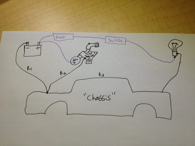
What you really care about here is the quality of the ground between the battery and ground, since you want the body of the car to act as an "extension" of the negative terminal of the battery.
As for the Alternator ground... yes, but there are so many junction points along the path between the alternator bracket and the battery terminal that are not necessarily bright shiny clean metal (bolts and surfaces and whatnot), that can add resistance along the way. So bypassing the engine block and all that junk, and going straight from the alty body to the neg terminal will give you less resistance. But that's the engine we're talking about, not the "chassis".
And iirc, the alternator is connected to the engine, which is connected via a wire to the chassis at the exact same place where the battery is connected to the chassis (the wires touch, so the resistance of the chassis is irrelevant here) meaning theyou actually add the resistance of those 2 factory wires plus all junctions in between together.... to get from the alty to the neg terminal.
The chassis is just a junction for that portion of the circuit (not a conductor), and you could just as easily connect the 2 wires together floating in mid-air using a plastic nut/bolt... as long as the 2 ends of the wire touch (and as long as the chassis was grounded to the battery somewhere else).
The only things that the chassis grounds are other circuits on the car that are grounded to the chassis, such as headlights, taillights, crap under the dashboard, etc. Those actually use the chassis as a conductor rather than a junction point.
the entire chassis over time rusts as do all bolts. this raises the resistance of the chassis. if you put 2 neg to chassis wires, this will lower resistance
and i dont really mind people are hating, I know it works so i enjoy everyones reaction hahhah :P guess i am half troll
and i dont really mind people are hating, I know it works so i enjoy everyones reaction hahhah :P guess i am half troll
And again you are describing the resistance BETWEEN the chassis ground-point and the battery... which is a wire, or in your case, 2 larger-than-stock wires. You are NOT describing the resistance of the chassis itself (between the "chassis ground point used to connect to the battery", and "every other ground point on the chassis used by other circuits").
Give me a minute and I will draw you a beautiful picture to explain this to you.
Last edited by CapedCadaver; Dec 11, 2012 at 09:30 PM.


Senior Member
Joined: Nov 2005
Posts: 1,155
From: Austin
I say let him do what he is going to do. He has already made it clear on his intelligence and maturity level. Just look at the pics of the engine bay. I would keep my distance from that car but have marshmallows and chocolate handy for when it.....


So when i say "the chassis has low resistance" i'm talking about R3. The resistance between two separate points on the chassis. That value will be lower than any wire you've got, assuming your connection points are nice and clean.
What you are calling the "resistance of the chassis" is R1 or R2. Those are wires, not "chassis".
So yes, reducing the resistance of those wires (by doubling them up, or making them thicker" will reduce the voltage drop across those wires, and therefore make more voltage available to the other parts of the car. If you had used a thicker wire (0 gauge) rather than doubling up the battery-to-chassis ground, you'd see the same result out a single wire though.
But that STILL has nothing to do with altering the resistance of the actual chassis (R3)... as i said twice before, you are talking about the connection BETWEEN the chassis and battery. The chassis itself is a massively big wire with massively low resistance, whether or not you can get the best use out of it a matter of what you're connecting to it, not it-itself.
And if there is paint, rust, dirt etc on your *connection points* then that's still not the "resistance of the chassis" as far as the metal in the chassis, that's just some junk you need to clean off before trying to make a connection.

Last edited by CapedCadaver; Dec 11, 2012 at 10:09 PM.


And here, I'll even praise you more, YOU'RE RIGHT ABOUT SOMETHING, but it's nothing new:
1. Stock grounds on almost all cars suck.
2. Stock grounds get worse as the car ages.
3. Replacing Stock grounds, and Adding extra grounds WILL help electrical performance, and extend the service life of all components involved.
Listen careful to the next part: This is why most guys upgrade the grounds. Some call it the 'big 3', whatever, the number doesn't matter, the purpose is to decrease the resistance to ground of the major ground points on a vehicle.
On every car the amount and location of the most vital points are different. But one thing is common, the 3 components you should be upgrading/adding grounds to:
1. Battery Negative to Chassis
2. Starter housing/Transmission Bellhousing to Chassis
3. Alternator housing/Engine block to Chassis
IMO:
- The Alternator should have it's own ground from the mounting bolt (alternator case)
- The battery negative should have 1 good 4 AWG ground that is under 14" long
- The Starter should be grounded from the mounting bolt to the Chassis with 4 AWG wire as short as possible while still allowing good routing and engine flex
- The timing case should be grounded to chassis with a 8 AWG wire. Alternatively you can run this 8 AWG wire over to the mounting point for your Alternator Ground so you don't have to run spagetti Grounds all over the bay. It will ground to chassis through the Alternators 4 AWG wire you just installed.
- Rear of engine block to chassis with 4 AWG
- Fuel pump ground to chassis (often overlooked, you do need to check the wiring diagram of your fuel pump though to make sure you can ground to chassis)
My point is to tell you what you should do. Anything more is overkill, but won't really hurt anything but your pocket-book, time, and the visual appearance, so long as you run the wires correctly.
My other point is that no one is saying you're wrong about your reasoning for upgrading grounds.
People are laughing because you're making outlandish, unsubstantiated claims about the results, AS WELL as doing a TERRIBLE, HIDEOUS, TEAR-JERKING job on your wiring.
Anyone with any competence is shaking their head profusely at your pictures.
The claims, no fuse, and all the other idiocy is just amplifying the ridicule.
Swallow your pride, eat some ****ing humble pie, and accept that you do not know much of anything about this stuff, despite what you think.
Only then might you actually be able to learn something. Because right now your head is far too enlarged with mis-information for any good, truthful info to get in.


Here, I'll quote the one thing you are saying that is certainly true.
And here, I'll even praise you more, YOU'RE RIGHT ABOUT SOMETHING, but it's nothing new:
1. Stock grounds on almost all cars suck.
2. Stock grounds get worse as the car ages.
3. Replacing Stock grounds, and Adding extra grounds WILL help electrical performance, and extend the service life of all components involved.
Barring that, as long as you clean it up good and use something to help ward off future corrosion/dirt (dielectric grease or something) then the grounding point should perform admirably for years to come.


Dude is just really confused about the whole thing.
I think he learnt 1 very, very, very simple thing about electricity, and now he thinks he knows everything.
We've all been there, it takes knowledge to step back and decide to
A) learn more or B) Do not profess to know anything
Either way, you will NEVER know it all. There will always be a guy who knows more, and just when you think you've wow'd everyone listening to your big INTERNET POST, someone smarter will come in and make you look like a moron.


Many resistors and conductors have a uniform cross section with a uniform flow of electric current and are made of one material. In this case, the electrical resistivity ρ is defined as:
P=R(A/L)
where R is the electrical resistance of a uniform specimen of the material (measured in ohms, Ω) L is the length of the piece of material (measured in meters, m) A is the cross-sectional area of the specimen (measured in square meters, m�). The reason resistivity is defined this way is that it makes resistivity a material property, unlike resistance. All copper wires, irrespective of their shape and size, have approximately the same resistivity, but a long, thin copper wire has a much larger resistance than a thick, short copper wire. Every material has its own characteristic resistivity�for example rubber's resistivity is far larger than copper's.
In a hydraulic analogy, passing current through a high-resistivity material is like pushing water through a pipe full of sand, while passing current through a low-resistivity material is like pushing water through an empty pipe. If the pipes are the same size and shape, the pipe full of sand has higher resistance to flow. But resistance is not solely determined by the presence or absence of sand; it also depends on how wide the pipe is (it is harder to push water through a skinny pipe than a wide one) and how long it is (it is harder to push water through a long pipe than a short one.)
This is why the extremely large steel conductor of the chassis has such a high conductivity when compared to the copper wire. Even though copper is a better conductor given all else being equal. (Copper's conductivity is about 5.96�107 σ (Siemens per Meter) where as steel is about 2.17�106 σ (S/m))
If you don't believe me, go ahead and buy a meter to measure it yourself. Just take whatever resistance readings you get and find the inverse. That will be your measurement in Siemens. (Although I am quite sure that anything you can afford or even have access to will not find any difference in resistance between the two. Most instruments will just read 0Ω)


Many resistors and conductors have a uniform cross section with a uniform flow of electric current and are made of one material. In this case, the electrical resistivity ρ is defined as:
P=R(A/L)
wall 'o text!
This is why the extremely large steel conductor of the chassis has such a high conductivity when compared to the copper wire. Even though copper is a better conductor given all else being equal. (Copper's conductivity is about 5.96�107 σ (Siemens per Meter) where as steel is about 2.17�106 σ (S/m))
If you don't believe me, go ahead and buy a meter to measure it yourself. Just take whatever resistance readings you get and find the inverse. That will be your measurement in Siemens. (Although I am quite sure that anything you can afford or even have access to will not find any difference in resistance between the two. Most instruments will just read 0Ω)
Heck if you know the density of steel and the weight of the car's unpainted bodyshell, and the length of "steel wire" that would match the length of the car, you could probably figure this out pretty quickly... How many cubic centimeters worth of metal is in the car's body... and what does that turn out to be in a cylindrical shape of a known length?


...
...
So let's put this into this simple voltage divider. Vin is 12v, Vout is what we are looking for. R1 is 1Ω and R2 is 3Ω.
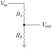
Vout = Vin ( R2 / (R1 + R2))
9v = 12v * (3 / (1 + 3))
9v = 12v * (3 / 4)
Bonus question: How many amps are flowing through R2? Through R1?
How many watts for R2? And R1?
...
...
So let's put this into this simple voltage divider. Vin is 12v, Vout is what we are looking for. R1 is 1Ω and R2 is 3Ω.
Vout = Vin ( R2 / (R1 + R2))
9v = 12v * (3 / (1 + 3))
9v = 12v * (3 / 4)
Bonus question: How many amps are flowing through R2? Through R1?
How many watts for R2? And R1?
...

Since this thread is already derailed, here's a serious question for the wookie:
I have some 4 Ohm tweeters I want to run in line with my factory tweeters to add a little more clarity to the factory Blows system. I know the Bose system is 2 Ohms, though. How do I drop resistance in the aftermarket tweeters to 2 Ohms? Splice in a 2 Ohm resistor...?
I sound like a n00b. But I only know basic electrical concepts.
a wire? or just a ground path through the metal bracket, engine block and eventually to the chassis-to-engine groundwire? I've only worked on a VG maxima before (electrically) so i don't know where the engine-to-chassis ground is on a 4th gen or 5th gen. On the 3rd gen VG motor it's on the coolant return tube from the radiator to the waterpump.
Since this thread is already derailed, here's a serious question for the wookie:
I have some 4 Ohm tweeters I want to run in line with my factory tweeters to add a little more clarity to the factory Blows system. I know the Bose system is 2 Ohms, though. How do I drop resistance in the aftermarket tweeters to 2 Ohms? Splice in a 2 Ohm resistor...?
I sound like a n00b. But I only know basic electrical concepts.
I have some 4 Ohm tweeters I want to run in line with my factory tweeters to add a little more clarity to the factory Blows system. I know the Bose system is 2 Ohms, though. How do I drop resistance in the aftermarket tweeters to 2 Ohms? Splice in a 2 Ohm resistor...?
I sound like a n00b. But I only know basic electrical concepts.

the resistance that matters (sound wise) is the resistance of the coil. Jumping around the coil with a resistor will double the amperage draw of the whole assembly (ie, might make the amp do more work as if you had 2Ω speakers attached), but it won't increase the draw through the coil, but it won't net you more sound (and might screw your existing sound up), so if you want a 2Ω speaker, buy a 2Ω speaker.
http://www.bcae1.com/spkrmlti.htm