
direct fuse box grounds


Buy new speakers 
the resistance that matters (sound wise) is the resistance of the coil. Jumping around the coil with a resistor will double the amperage draw of the whole assembly (ie, might make the amp do more work as if you had 2Ω speakers attached), but it won't increase the draw through the coil, but it won't net you more sound (and might screw your existing sound up), so if you want a 2Ω speaker, buy a 2Ω speaker.
http://www.bcae1.com/spkrmlti.htm
 I hate working on Bose systems. It was a nightmare trying to install a sub on the Z to replace the shoddy factory one.
I'll give that a read, though.
Oooh you edited it after I skimmed through it I guess, or I just missed it. I thought you were talking about the picture you drew lol. The one with no values.
And yes iirc there is a joke of a wire dangling of the bracket that grounds by the washer reservoir spot. I'm not going out to look though could be wrong.

And yes iirc there is a joke of a wire dangling of the bracket that grounds by the washer reservoir spot. I'm not going out to look though could be wrong.
Oooh you edited it after I skimmed through it I guess, or I just missed it. I thought you were talking about the picture you drew lol. The one with no values.
And yes iirc there is a joke of a wire dangling of the bracket that grounds by the washer reservoir spot. I'm not going out to look though could be wrong.
And yes iirc there is a joke of a wire dangling of the bracket that grounds by the washer reservoir spot. I'm not going out to look though could be wrong.

Senior Member
Joined: Oct 2009
Posts: 1,432
This thread had me laughing my *** off for past 25 minutes But on Same note i Learned quite a bit about eltrical from reading and reading and reading lmfao..
I now now have a question....how do u guys find such funny pics that describe the situation so well? lmao do ya google that **** real quick or what!! i wanna join the be a ****head to Noobs party lmao jk....im always nice.
I now now have a question....how do u guys find such funny pics that describe the situation so well? lmao do ya google that **** real quick or what!! i wanna join the be a ****head to Noobs party lmao jk....im always nice.

Now I'm going to take my cookies and spend some quality time with my Maxima. I have lots and lots of ground wire to add.

This thread had me laughing my *** off for past 25 minutes But on Same note i Learned quite a bit about eltrical from reading and reading and reading lmfao..
I now now have a question....how do u guys find such funny pics that describe the situation so well? lmao do ya google that **** real quick or what!! i wanna join the be a ****head to Noobs party lmao jk....im always nice.
I now now have a question....how do u guys find such funny pics that describe the situation so well? lmao do ya google that **** real quick or what!! i wanna join the be a ****head to Noobs party lmao jk....im always nice.
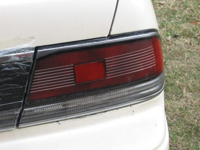
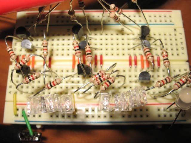
This is a logic board (and test LEDs) for a full-panel multicolor taillight setup that i was working on for my 3rd gen at the time. Basically if you are only signalling, it's all yellow. If you are only braking, it's all red. If you are only backing up, it's all white. If you are doing multiple things together, different sections display different colors.
Just imagine that each of the 3 lit-up LEDs represents one "chunk" of the taillight surface. Above, behind, and below the pinstripes. On a 89-91SE, the red thing comes out and you're left with a clear lens (other than the red reflector in the center), so you can get more creative with your lighting.
(video link)
Last edited by CapedCadaver; Dec 11, 2012 at 11:27 PM.

I had a period of time at work last year where I wasn't very busy, and some of my close-by coworkers had studied electrical engineering in college... so I spent a while picking their brains and d1cking around with some breadboard circuitry.
This is a logic board (and test LEDs) for a full-panel multicolor taillight setup that i was working on for my 3rd gen at the time. Basically if you are only signalling, it's all yellow. If you are only braking, it's all red. If you are only backing up, it's all white. If you are doing multiple things together, different sections display different colors.
(video link)
I had been thinking of doing something very similar for my 5th Gen. The wiring shouldn't be too difficult. Making it look good is what has me stumped. I just refuse to ghetto my Max. I might buy a set of cheap aftermarkets (OEM style) and modify them in my free time just to see what I can come up with.
The logic for that setup is actually a pain in the butt... basically you have to decide what colors to disable in what sections, while maintaining some sort of priority/affinity so that each section only lights up one color at a time.
Here was the truth table for mine. Inputs on left, outputs on right (in the order of top-middle-bottom)
0 inputs:
nothing = dark dark dark
1 input:
Brake = red red red
blinker = amber amber amber
reverse = white white white
2 inputs:
brake + blinker = amber red red
brake + reverse = red red white
blinker + reverse = amber amber white
3 inputs:
brake + blinker + reverse = amber red white
This is what i came up with (for non-RGB LEDs) after a while, but it's still not correct/finished.
http://www.falstad.com/circuit/#%24+...8+512+496+0%0A
Each group of 3 (counted from the top down) is one "section" of the light. Just imagine it as being 100 LEDs instead of 1.
Top switch is reverse. Middle switch is blinker. Bottom switch is brakes.
http://www.falstad.com/circuit/#%24+...8+512+496+0%0A
Each group of 3 (counted from the top down) is one "section" of the light. Just imagine it as being 100 LEDs instead of 1.
Top switch is reverse. Middle switch is blinker. Bottom switch is brakes.
i added more pics on the post you quoted.
The logic for that setup is actually a pain in the butt... basically you have to decide what colors to disable in what sections, while maintaining some sort of priority/affinity so that each section only lights up one color at a time.
Here was the truth table for mine. Inputs on left, outputs on right (in the order of top-middle-bottom)
0 inputs:
nothing = dark dark dark
1 input:
Brake = red red red
blinker = amber amber amber
reverse = white white white
2 inputs:
brake + blinker = amber red red
brake + reverse = red red white
blinker + reverse = amber amber white
3 inputs:
brake + blinker + reverse = amber red white
i need to add n-channel for every p-channel to turn those into CMOS inverters, so i don't have residual voltage on the backside of those p-channels every time i cut a switch off.
Think of it like a bath tub with a both a lower spigot and a shower head... after you cut off the water, you need to turn it back to the lower faucet to drain out what's left in the shower head hose.
"CMOS inverter - slow transition" kind of lets you see that in action. Click the letter on the left to change the state of the one on the right.
Well i also added an LED to it, and turned on the current dots..
http://www.falstad.com/circuit/#%24+...+0.025+2+-1%0A
Last edited by CapedCadaver; Dec 11, 2012 at 11:56 PM.
I was thinking of something a little more complicated actually. I wanted my flashing lights (Emergency and Turn Signals) to kind of radiate from the center and brighten down and out. (Damn circular tail lights.) And the break lights to start at the center and brighten upward. I am thinking I could pull it off with a micro controller like an Arduino kit or something. The programming is something I'm going to have to look into though.
My goal was simply to have the entire taillight area fully utilized at all times when *anything* needed to be lit up... rather than only portions of it being used at any given time.
My running lights were going to be in the whitish area underneath the red, which is currently the white/amber for the reverse and turn respectively.

I'll probably end up doing something similar for mine. I plan on using surface mount LEDS though. When I plan the board I will try to leave a way to address each 'row' individually so that I can add programming later if I want to.
well if you got the clear tails you could do something like mine, with LEDs around the perimiter of the big circle as your "running lights" at night.

Same order, top (stock brakes), middle (stock blinker), bottom (stock reverse):
0 inputs:
nothing = dark dark dark
1 input:
Brake = red red red
blinker = amber amber amber
reverse = white white white
2 inputs:
brake + blinker = red amber red
brake + reverse = red red white
blinker + reverse = amber amber white
3 inputs:
brake + blinker + reverse = red amber white
Also would need to apply a small amount of red tint on the outside, over top of the now-white reflector strip, to make them street-legal again. I guess masking it off and hitting it with some red VHT would work.
Last edited by CapedCadaver; Dec 12, 2012 at 12:13 AM.
Or could make the stock reverse light the new running light (in addition to the ring/line in the main section) and split the main section into 3 sections... inner, outer top, and outer bottom. In the 3-input scenario, the inners would be red, and the outers would either be amber or white.
I'd rather have amber/white closer to the outside of the car so it's easier for approaching cars to see in the parking lot, and for passing/lane changes on the road. Nobody who isn't directly behind you needs to see your brake lights as much as they need to see your blinkers or reverse lights...
again this is just what it would look like for "three inputs on", if it was just brakes the whole thing would be red, if it was just blinkers the whole thing amber, brake+blinker would be inside-red-outside-amber, etc.
Last edited by CapedCadaver; Dec 12, 2012 at 12:14 AM.
heh, so apparently the FSM even has a description of voltage drop in it... starting at the bottom of GI-27 thru the top of GI-29
http://www.nicoclub.com/FSM/maxima/2000/gi.pdf
http://www.nicoclub.com/FSM/maxima/2000/gi.pdf
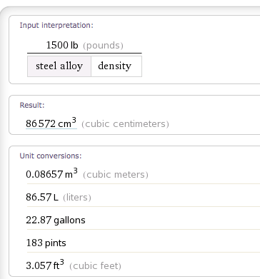
also i just found out how big-around a steel "wire" (cylinder) with approximately the same weight and length as a Maxima unibody would be (assuming the steel body of the car is 1500lb with no wiring, glass, interior,paint etc)... would be almost 6 inches thick.
Tell me THAT doesn't have "less resistance" than a 4-gauge wire.... that's the reason why i said grounding an amp in the trunk will give much better results than grounding an amp with a (comparitively puny) wire strung all the way up to the battery will give a better ground.. because of how thick the steel is.
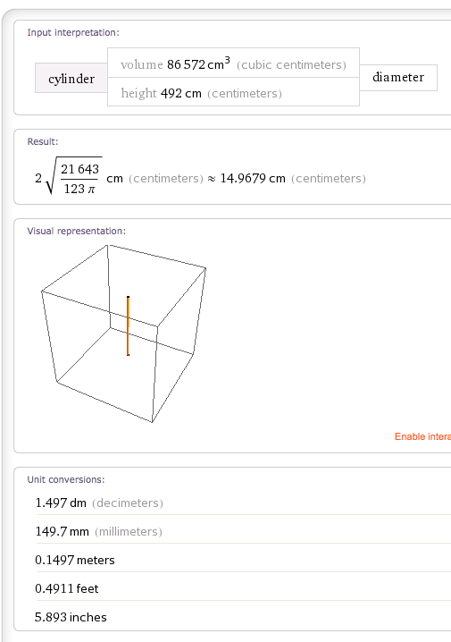
Tell me THAT doesn't have "less resistance" than a 4-gauge wire.... that's the reason why i said grounding an amp in the trunk will give much better results than grounding an amp with a (comparitively puny) wire strung all the way up to the battery will give a better ground.. because of how thick the steel is.
Last edited by CapedCadaver; Dec 12, 2012 at 03:00 AM.
Oooh you edited it after I skimmed through it I guess, or I just missed it. I thought you were talking about the picture you drew lol. The one with no values.
And yes iirc there is a joke of a wire dangling of the bracket that grounds by the washer reservoir spot. I'm not going out to look though could be wrong.
And yes iirc there is a joke of a wire dangling of the bracket that grounds by the washer reservoir spot. I'm not going out to look though could be wrong.

uhh ok.
the more metal/wire the more resistance
-This applies to wires and the chassis of a car
more resistance = less voltage
if you can lower the resistance of the cars chassis by adding ground wires, the overall voltage of every component will rise
voltage division occurs when a central ground/power location is split to 2 separate paths, the voltage is equally distributed as long as the same wire/crimps are used
since a car chassis is a lot of steel, it will take multiple ground wires to get a strong ground. (the more steel, the more voltage pathways are needed)
nowww if you attach a ground wire to a 1x1ft piece of steel, and then the same wire to a 2x2ft piece of steel, the ground would be stronger on the smaller piece of steel rather than a bigger one
the electricity has less distance to travel, thus less resistance, thus more voltage
You must be joking...now your just insulting me and my profession. Quit while your ahead

Thread Starter
Member
Joined: May 2011
Posts: 211
The resistance of the chassis IS low... i'm talking about the unibody of the car here. If you took the car and crushed it into a wire-like shape (after removing everything that wasn't metal) you'd find it to be a much thicker wire than any wire you were using.
And 2 grounds to the chassis isn't anything to do with the resistance of the chassis itself, which is why I said:
The resistance of the wire between the battery and the chassis does NOT equal "the resistance of the chassis itself".
As for the Alternator ground... yes, but there are so many junction points along the path between the alternator bracket and the battery terminal that are not necessarily bright shiny clean metal (bolts and surfaces and whatnot), that can add resistance along the way. So bypassing the engine block and all that junk, and going straight from the alty body to the neg terminal will give you less resistance. But that's the engine we're talking about, not the "chassis".
And iirc, the alternator is connected to the engine, which is connected via a wire to the chassis at the exact same place where the battery is connected to the chassis (the wires touch, so the resistance of the chassis is irrelevant here) meaning theyou actually add the resistance of those 2 factory wires plus all junctions in between together.... to get from the alty to the neg terminal.
The chassis is just a junction for that portion of the circuit (not a conductor), and you could just as easily connect the 2 wires together floating in mid-air using a plastic nut/bolt... as long as the 2 ends of the wire touch (and as long as the chassis was grounded to the battery somewhere else).
The only things that the chassis grounds are other circuits on the car that are grounded to the chassis, such as headlights, taillights, crap under the dashboard, etc. Those actually use the chassis as a conductor rather than a junction point.
stop trying to write big paragraphs with big words to gain credibility
Thread Starter
Member
Joined: May 2011
Posts: 211
the body would have to rust through ENTIRELY between point A and point B for this to hold true. Take a big piece of sheet metal and drill a hole through it to simulate "rust" and the resistance won't really change appreciably..
And again you are describing the resistance BETWEEN the chassis ground-point and the battery... which is a wire, or in your case, 2 larger-than-stock wires. You are NOT describing the resistance of the chassis itself (between the "chassis ground point used to connect to the battery", and "every other ground point on the chassis used by other circuits").
Give me a minute and I will draw you a beautiful picture to explain this to you.
take 2 pieces of sheet metal. use 1 bolt to hold both together. measure resistance
now wait ten yesrs for the bolt to rust
remeasure resistance
guaranteed gain in resistance
the unibody rusts and increases resistance throughout the entire car
your bonus question is unjust, I dont care for r1x3.4523 + R2D2 = luke skywalker
You say adding two negative to chassis will not change anything, you are wrong. I have TESTED it
you say the chassis is not a conductor, WRONG
you take everything I say, mold it to something different, then elaborate on it to try to make me look small
all this form cares about is telling everyone how wrong they are.. well keep telling me cause I find it amusing
I put everthing I said to the test and idc if your an electrical engineer, tunermaxima, or luke skywalker, everything I have been saying makes sense and works amazing
Last edited by Aviation005; Dec 12, 2012 at 05:39 AM.

Here's a tip: calling smart people smart, or old people old... these things aren't actually insults. They are, however, behavioral markers for insecurity. So you've got that going for you.
Here's another tip: there comes a point in any discussion between amateur and expert, where the first realizes they are out of their depth. I think it goes without saying (and yet), that moment came and went a long, long time ago.
Thread Starter
Member
Joined: May 2011
Posts: 211
OMG THERE IS NO FUSE ON THE ALTERNATOR TO POSITIVE LINE OMG OMG
now im trolling hahahah
is there an easy way to directly ground the alternator without having to remove its main bolts/ac compressor? I would have loved to ground it, but I cannot find a place
now im trolling hahahah
is there an easy way to directly ground the alternator without having to remove its main bolts/ac compressor? I would have loved to ground it, but I cannot find a place
Last edited by Aviation005; Dec 12, 2012 at 07:08 AM.


 wtf is this?


