
direct fuse box grounds
 12-11-2012, 04:08 PM
#1
Member
Thread Starter

Join Date: May 2011
Posts: 211
direct fuse box grounds
Seeing as my old thread was unreasonably closed, here are the pics I was trying to provide
This provides a perfect ground to the fuse box, due to being attached directly to the negative terminal


did it to both fuse box grounds
the reason I did this is cause the chassis ground is not exactly the best.
All the chassis is bolted together, over time it all rusts and reduces conductivity throughout the entire car. You are relying on painted steel and rusted bolts as your line of conductivity
did you know those fuse box grounds were grounded to painted steel? the only point of contact was the bolt.. which was as you guessed it, rusted
if nissan did not take the time to sand off 3mm of paint there, do you honestly think they put effort into all the other parts?
if you take all that I'm saying in, and leave your ego out, it will all make sense
-I dont understand why are all nooo noooo noooooo, like shut the **** up, this is my car not yours

Here is the intake repositioned, I got it as deep as I could under the battery
as you can tell I'm not here to make friends, i'm here to share what worked really well for my car
This provides a perfect ground to the fuse box, due to being attached directly to the negative terminal
did it to both fuse box grounds
the reason I did this is cause the chassis ground is not exactly the best.
All the chassis is bolted together, over time it all rusts and reduces conductivity throughout the entire car. You are relying on painted steel and rusted bolts as your line of conductivity
did you know those fuse box grounds were grounded to painted steel? the only point of contact was the bolt.. which was as you guessed it, rusted
if nissan did not take the time to sand off 3mm of paint there, do you honestly think they put effort into all the other parts?
if you take all that I'm saying in, and leave your ego out, it will all make sense
-I dont understand why are all nooo noooo noooooo, like shut the **** up, this is my car not yours
Here is the intake repositioned, I got it as deep as I could under the battery
as you can tell I'm not here to make friends, i'm here to share what worked really well for my car
Last edited by Aviation005; 12-11-2012 at 04:11 PM.


 12-11-2012, 04:15 PM
#3
Member
Thread Starter
Join Date: May 2011
Posts: 211
how about commenting instead of making immature picture comments?
12-11-2012, 04:31 PM
#5
Member
Thread Starter
Join Date: May 2011
Posts: 211
everyone on this forum is a ****
you have 6,088 points, this makes you GOD
just because my method is different, does not mean its wrong and does not work great
you have 6,088 points, this makes you GOD
just because my method is different, does not mean its wrong and does not work great

 12-11-2012, 05:08 PM
#10
Member
Thread Starter
Join Date: May 2011
Posts: 211
this is why i said leave your ego aside
apparently people nowadays no longer have this ability
you negatively speak of my mod, without any reason
I think its the fact i'm new to the forums and making write ups.. the SR members dont seem to like it too much
apparently people nowadays no longer have this ability
you negatively speak of my mod, without any reason
I think its the fact i'm new to the forums and making write ups.. the SR members dont seem to like it too much
12-11-2012, 05:57 PM
#11

JK, JK. (inside Org joke)
Well, you are new, but that's not it, boss. I know it's nigh impossible to see your own headlights from the driver's seat, but you're coming on pretty strong here, and the natural inclination for some of these senior members is to slap you back. Your best course of action is to take it down a notch (or two or five). Ride out the forum for a while (months) before attempting write-ups. Research and learn about your car more, instead of making big statements about junkyard mods.
Some of these people you think are d1cks actually do know quite a bit about the Maxima. Point in fact, most of them are a pretty decent sort.
Good luck.

 12-11-2012, 06:17 PM
#17
Member
Thread Starter
Join Date: May 2011
Posts: 211
You don't happen to own a laundromat, do you? Pole-dance on the side, maybe?
JK, JK. (inside Org joke)
Well, you are new, but that's not it, boss. I know it's nigh impossible to see your own headlights from the driver's seat, but you're coming on pretty strong here, and the natural inclination for some of these senior members is to slap you back. Your best course of action is to take it down a notch (or two or five). Ride out the forum for a while (months) before attempting write-ups. Research and learn about your car more, instead of making big statements about junkyard mods.
Some of these people you think are d1cks actually do know quite a bit about the Maxima. Point in fact, most of them are a pretty decent sort.
Good luck.
what pisses me off is they come into my thread trying to say how terrible of an idea it is and it wont fix anything. this is just rude and wrong
the SRs were wrong about my valve noise, and my 340LPH fuel pump (which works amazing btw)
hmm.
Last edited by Aviation005; 12-11-2012 at 06:25 PM.


 12-11-2012, 06:23 PM
#23
Member
Thread Starter
Join Date: May 2011
Posts: 211
the more metal/wire the more resistance
-This applies to wires and the chassis of a car
more resistance = less voltage
if you can lower the resistance of the cars chassis by adding ground wires, the overall voltage of every component will rise
voltage division occurs when a central ground/power location is split to 2 separate paths, the voltage is equally distributed as long as the same wire/crimps are used
since a car chassis is a lot of steel, it will take multiple ground wires to get a strong ground. (the more steel, the more voltage pathways are needed)
nowww if you attach a ground wire to a 1x1ft piece of steel, and then the same wire to a 2x2ft piece of steel, the ground would be stronger on the smaller piece of steel rather than a bigger one
the electricity has less distance to travel, thus less resistance, thus more voltage
Last edited by Aviation005; 12-11-2012 at 06:30 PM.
 12-11-2012, 06:38 PM
#25
 12-11-2012, 06:55 PM
#26

uhh ok.
the more metal/wire the more resistance
-This applies to wires and the chassis of a car
more resistance = less voltage
if you can lower the resistance of the cars chassis by adding ground wires, the overall voltage of every component will rise
voltage division occurs when a central ground/power location is split to 2 separate paths, the voltage is equally distributed as long as the same wire/crimps are used
since a car chassis is a lot of steel, it will take multiple ground wires to get a strong ground. (the more steel, the more voltage pathways are needed)
nowww if you attach a ground wire to a 1x1ft piece of steel, and then the same wire to a 2x2ft piece of steel, the ground would be stronger on the smaller piece of steel rather than a bigger one
the electricity has less distance to travel, thus less resistance, thus more voltage
 12-11-2012, 06:57 PM
#27

Sorry man. You kiind of know what you're talking about, and I'm glad it works for you, but you have some things to learn about joining a forum, especially one as old and established as this. People here (with a couple exceptions) are more than happy to help and have a lot of knowledge; more than you. More than me. Try having a slice of humble pie or your threads will keep getting locked and people will keep trying to run you out. Right now you're up Sht Creek without a paddle. Good luck getting back...
12-11-2012, 07:00 PM
#28
Senior Member

Join Date: May 2012
Location: vancouver
Posts: 336
this turned my horrible day i to something special! OP i wont even start on the electrical stuff you have hacked away at.. but do you know what would be super uber cool? i can tell you would like it! i have a feeling its your kinda style! you should totally cut a 3 inch hole in your hood and route that dryer intake up your windshield to the roof bro!!!! u could like, drive it through water and shiet like the 4x4s do!!!! and with the good grounding you have done, at least you know you will get your windows up fast if the water gets too deep!
Last edited by user name001; 12-11-2012 at 07:12 PM.
 12-11-2012, 07:20 PM
#30
this turned my horrible day i to something special! OP i wont even start on the electrical stuff you have hacked away at.. but do you know what would be super uber cool? i can tell you would like it! i have a feeling its your kinda style! you should totally cut a 3 inch hole in your hood and route that dryer intake up your windshield to the roof bro!!!! u could like, drive it through water and shiet like the 4x4s do!!!! and with the good grounding you have done, at least you know you will get your windows up fast if the water gets too deep!
Rerouting one of the ground cables towards the main cable coming from the alternator would be a much wiser. Could easily increase roll up speed of windows, brighter lights and best of all car will become much more responsive.
 12-11-2012, 07:35 PM
#33
uhh ok.
the more metal/wire the more resistance
-This applies to wires and the chassis of a car
more resistance = less voltage
if you can lower the resistance of the cars chassis by adding ground wires, the overall voltage of every component will rise
voltage division occurs when a central ground/power location is split to 2 separate paths, the voltage is equally distributed as long as the same wire/crimps are used
since a car chassis is a lot of steel, it will take multiple ground wires to get a strong ground. (the more steel, the more voltage pathways are needed)
nowww if you attach a ground wire to a 1x1ft piece of steel, and then the same wire to a 2x2ft piece of steel, the ground would be stronger on the smaller piece of steel rather than a bigger one
the electricity has less distance to travel, thus less resistance, thus more voltage
the more metal/wire the more resistance
-This applies to wires and the chassis of a car
more resistance = less voltage
if you can lower the resistance of the cars chassis by adding ground wires, the overall voltage of every component will rise
voltage division occurs when a central ground/power location is split to 2 separate paths, the voltage is equally distributed as long as the same wire/crimps are used
since a car chassis is a lot of steel, it will take multiple ground wires to get a strong ground. (the more steel, the more voltage pathways are needed)
nowww if you attach a ground wire to a 1x1ft piece of steel, and then the same wire to a 2x2ft piece of steel, the ground would be stronger on the smaller piece of steel rather than a bigger one
the electricity has less distance to travel, thus less resistance, thus more voltage

You could've had the self decency to search on Wikipedia or Google before you posted this to make an *** of yourself.
But if you had, I'd have lost out on the lol's I just got. So carry on.
Please, next can we get a lesson voltage drop?
Oh, and where's the link I CLEARLY requested for the gerber knife you used to masterfully shave the paint off those connections?
OH and can you also link to me where you bought that beautiful shrink tubing and the zip ties and P-Clamps you used as well?
Oh. wait.
12-11-2012, 07:37 PM
#34
Senior Member
Join Date: May 2012
Location: vancouver
Posts: 336
lol what is this gerber knife?
 12-11-2012, 08:01 PM
#36
So yeah your answer pretty much told me what I thought... you don't know what i mean by voltage drop. or voltage divider.
er... "more metal/wire" in terms of length or thickness? Length yes, resistance-per-unit-length at a certain gauge of wire is measurable. Thickness no, the thicker the wire then the less specific resistance it will have per unit-length.
Also the chassis of the car itself has a very low resistance compared to wires because the entire body shell/frame of the car is a very "fat wire" of a conductor, so grounding something in the trunk (like an amp) to the body of the car will actually be a better ground than running a ground wire all the way from the amp (in the trunk) to the battery.
Similarly if you have your battery in the trunk you definitely want it to ground to the body right there by the battery, then ground the engine to the chassis under the hood. This is what BMW does from the factory on the E39 (and probably others, only ever been under the hood/trunk of an E39).
what the actual ****? no. no no no no no. You're talking about AMPERAGE here, not voltage. Splitting a circuit into 2 paths (say, from 1x100Ω into 2x200Ω in parallel) will split the amperage equally between the 2 paths, but the voltage drop across both resistors will be the same, and definitely not different from one another.
Voltage division is the principle that the voltage measured at any point along a circuit is proportional to the amount of resistance it has already gone through vs the total resistance in the circuit. If you have a 12v power source, and 2 resistors (1x1Ω and 1x3Ω) for a total of 4Ω, then putting them in series (+12vdc then 1Ω then 3Ω then ground) you would measure 12v before the first resistor, 9v between them, and 0v after the last one, compared to ground. If you reverse the order of the resistors, you'd see 3v between them since the larger valued resistor came first. Of course this is all assuming wires of "zero resistance", but in reality the resistance of the wires would have to be accounted for as well assuming there were any.
So let's put this into this simple voltage divider. Vin is 12v, Vout is what we are looking for. R1 is 1Ω and R2 is 3Ω.
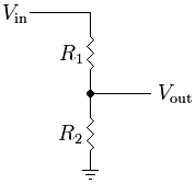
Vout = Vin ( R2 / (R1 + R2))
9v = 12v * (3 / (1 + 3))
9v = 12v * (3 / 4)
Bonus question: How many amps are flowing through R2? Through R1?
How many watts for R2? And R1?
 what are you smoking? is it legal? CAN I HAVE SOME?!?!
the "amount of steel" in the chassis actually makes it have a LOWER resistance, not a higher one. Even so, that has nothing to do with the "effectiveness" of a wire of any given size to do a "good job" grounding to a certain thing. And the amount of metal in the chassis also makes it better able to dissipate the wattage/heat any voltage dropped across it than a wire is. What you really care about here is the quality of the ground between the battery and ground, since you want the body of the car to act as an "extension" of the negative terminal of the battery.
all other things equal, yes. this is the only part you really got right. But it seems you are confusing amps with volts.... if you think of electricity like compressed air... voltage is your PSI, and amps is your CFM. And how much pressure you lose between resistance points is a product of the relative resistances of those points.
Wattage comes in to play when you multiply the *voltage drop between 2 points* by the ampreage flowing through the circuit... and wattage is heat. Heat melts wires. And that's what fuses are there for. Fuses are calibrated so that they will drop enough voltage across the fuse element at a certain amperage to achieve enough wattage to heat up the element and break it.
So without a proper fuse... your (thinner/higher resistance) wiring becomes the fuse... and heats up and breaks, or melts through the insulator and shorts against something else causing OTHER wires to transmit far more amperage than they are supposed to.... things get ugly.
Similarly if you have your battery in the trunk you definitely want it to ground to the body right there by the battery, then ground the engine to the chassis under the hood. This is what BMW does from the factory on the E39 (and probably others, only ever been under the hood/trunk of an E39).
Voltage division is the principle that the voltage measured at any point along a circuit is proportional to the amount of resistance it has already gone through vs the total resistance in the circuit. If you have a 12v power source, and 2 resistors (1x1Ω and 1x3Ω) for a total of 4Ω, then putting them in series (+12vdc then 1Ω then 3Ω then ground) you would measure 12v before the first resistor, 9v between them, and 0v after the last one, compared to ground. If you reverse the order of the resistors, you'd see 3v between them since the larger valued resistor came first. Of course this is all assuming wires of "zero resistance", but in reality the resistance of the wires would have to be accounted for as well assuming there were any.
So let's put this into this simple voltage divider. Vin is 12v, Vout is what we are looking for. R1 is 1Ω and R2 is 3Ω.
Vout = Vin ( R2 / (R1 + R2))
9v = 12v * (3 / (1 + 3))
9v = 12v * (3 / 4)
Bonus question: How many amps are flowing through R2? Through R1?
How many watts for R2? And R1?
since a car chassis is a lot of steel, it will take multiple ground wires to get a strong ground. (the more steel, the more voltage pathways are needed)
nowww if you attach a ground wire to a 1x1ft piece of steel, and then the same wire to a 2x2ft piece of steel, the ground would be stronger on the smaller piece of steel rather than a bigger one
nowww if you attach a ground wire to a 1x1ft piece of steel, and then the same wire to a 2x2ft piece of steel, the ground would be stronger on the smaller piece of steel rather than a bigger one
what are you smoking? is it legal? CAN I HAVE SOME?!?!the "amount of steel" in the chassis actually makes it have a LOWER resistance, not a higher one. Even so, that has nothing to do with the "effectiveness" of a wire of any given size to do a "good job" grounding to a certain thing. And the amount of metal in the chassis also makes it better able to dissipate the wattage/heat any voltage dropped across it than a wire is. What you really care about here is the quality of the ground between the battery and ground, since you want the body of the car to act as an "extension" of the negative terminal of the battery.
Wattage comes in to play when you multiply the *voltage drop between 2 points* by the ampreage flowing through the circuit... and wattage is heat. Heat melts wires. And that's what fuses are there for. Fuses are calibrated so that they will drop enough voltage across the fuse element at a certain amperage to achieve enough wattage to heat up the element and break it.
So without a proper fuse... your (thinner/higher resistance) wiring becomes the fuse... and heats up and breaks, or melts through the insulator and shorts against something else causing OTHER wires to transmit far more amperage than they are supposed to.... things get ugly.
Last edited by CapedCadaver; 12-12-2012 at 01:32 AM.
12-11-2012, 08:20 PM
#38
Member
Thread Starter
Join Date: May 2011
Posts: 211
all other things equal, yes. this is the only part you really got right. But it seems you are confusing amps with volts.... if you think of electricity like compressed air... voltage is your PSI, and amps is your CFM. And how much pressure you lose between resistance points is a product of the relative resistances of those points.
Wattage comes in to play when you multiple voltage drop across 2 points by the ampreage flowing through the circuit... and wattage is heat. Heat melts wires. And that's what fuses are there for. Fuses are calibrated so that they will drop enough voltage across the fuse element at a certain amperage to achieve enough wattage to heat up the element and break it.
So without a proper fuse... your (thinner/higher resistance) wiring becomes the fuse... and heats up and breaks, or melts through the insulator and shorts against something else causing OTHER wires to transmit far more amperage than they are supposed to.... things get ugly.
the chassis's resistance isnt exactly low, it all depends on the connection from the negative terminal of the battery. this is why i used 2 negative to chassis
and where exactly is the alternators ground? isnt it through the engine?
Last edited by Aviation005; 12-11-2012 at 08:37 PM.
12-11-2012, 08:34 PM
#39
And if you don't believe me, go measure the resistance of the 2 filaments in a 1157 bulb or other dual-filament bulb against the bulb casing. The dim filament will be higher resistance than the low one.
(12 to 13.5)^2 / <resistance-of-filament> should give you a number pretty darn close to what's printed on the label as the wattage of each filament.
Though, the low-wattage (higher resistance) filament should drop slightly more voltage between the socket connectors than the high-wattage (lower resistance) due to the low-wattage filament's resistance comprising a higher proportion of the total circuit resistance (including wiring, switches, fuses etc).
If the sockets have exposed metal on the backside where you can put a multimeter... if you measure hot-to-ground across both bulbs (will need someone pushing the brake pedal if it's a brakelight) then you should see a slightly higher voltage value for the parking light filament vs the brake light filament, since you are measuring voltage drop.
You can see it with LEDs connected to a breadboard (putting 3 LEDs instead of 4 in series causes the resistor to have more voltage to drop).